EP0352625B1 - Dispositif de pliage de feuilles pour machine d'impression - Google Patents
Dispositif de pliage de feuilles pour machine d'impression Download PDFInfo
- Publication number
- EP0352625B1 EP0352625B1 EP89113278A EP89113278A EP0352625B1 EP 0352625 B1 EP0352625 B1 EP 0352625B1 EP 89113278 A EP89113278 A EP 89113278A EP 89113278 A EP89113278 A EP 89113278A EP 0352625 B1 EP0352625 B1 EP 0352625B1
- Authority
- EP
- European Patent Office
- Prior art keywords
- eccentric shaft
- cylinder
- folding
- sheet
- disc
- Prior art date
- Legal status (The legal status is an assumption and is not a legal conclusion. Google has not performed a legal analysis and makes no representation as to the accuracy of the status listed.)
- Expired - Lifetime
Links
- 210000002105 tongue Anatomy 0.000 claims abstract 5
- 230000009467 reduction Effects 0.000 claims description 3
- 238000000034 method Methods 0.000 description 21
- 230000008569 process Effects 0.000 description 21
- 230000008901 benefit Effects 0.000 description 5
- 230000008859 change Effects 0.000 description 2
- 239000000428 dust Substances 0.000 description 2
- 230000002441 reversible effect Effects 0.000 description 2
- 230000004323 axial length Effects 0.000 description 1
- 230000005540 biological transmission Effects 0.000 description 1
- 230000007246 mechanism Effects 0.000 description 1
Images

Classifications
-
- B—PERFORMING OPERATIONS; TRANSPORTING
- B65—CONVEYING; PACKING; STORING; HANDLING THIN OR FILAMENTARY MATERIAL
- B65H—HANDLING THIN OR FILAMENTARY MATERIAL, e.g. SHEETS, WEBS, CABLES
- B65H45/00—Folding thin material
- B65H45/12—Folding articles or webs with application of pressure to define or form crease lines
- B65H45/16—Rotary folders
- B65H45/162—Rotary folders with folding jaw cylinders
- B65H45/163—Details of folding jaws therefor
Definitions
- the above invention relates to a sheet folding machine for a printing press.
- a folding process of the sheets is carried out using a plurality of pliers-like, controllable grippers.
- the pliers consist of a fixed part of the pliers and a movable part of the pliers and are distributed over the entire axial length of the folding cylinder.
- two flanges in the form of disks arranged side by side are provided on each side of the cylinder, which are mounted one below the other and opposite the cylinder by means of screws and continuous shafts.
- the disc-like flanges are against each other opposite directions of rotation pivotable using an eccentric shaft.
- This eccentric shaft is used to set the pliers gap (d). It is continuous and has offset eccentrics for the disk-like flanges.
- the eccentric shaft protrudes from the folding cylinder via a hexagon head, which enables the eccentric shaft to be operated by hand by attaching a key.
- Each movable pliers part is operatively connected via a ball bearing or a similar means to a cam disk which controls the opening and closing movement of the movable pliers parts relative to the fixed pliers parts during the rotational movement of the folding cylinder.
- the structure of a folding cylinder described so far is known in printing presses.
- the folding cylinder in order to change the pliers gap between the permanently arranged pliers parts and the movably arranged pliers parts, the folding cylinder has to be stopped, which in turn requires the entire rotary printing machine to be stopped.
- an operator has to loosen all the clamping screws of the disk-shaped flanges on both sides of the folding cylinder, for example, seven clamping screws must be opened on each folding cylinder side with seven folding pliers provided, after which the operator must carry out the necessary adjustment work by using an appropriate one Key on the protruding hexagon head of the eccentric shaft. After carrying out the adjustment work, the operator has to tighten all the clamping screws again and only then can the rotary printing machine be put into operation again.
- the setting process of the pliers gap is still a process that is carried out empirically. As already mentioned before, these adjustment processes have to be carried out very precisely, readjustments often have to be carried out in a fraction of a few millimeters or tenths of a millimeter. If it can be determined after restarting the rotary printing press that the setting work was not carried out satisfactorily or that the sheets are not gripped and held securely by the folding pliers after the setting process has been carried out, it will be necessary again to stop the rotary printing press in order to carry out the described setting operations again in their entirety. It can be stated that the setting processes of the folding pliers gap still represent one of the working processes for which the entire rotary printing press has to be stopped.
- the object of the above invention is to propose an improved folding cylinder with which the disadvantages of the known folding cylinders are eliminated and in which a direct, automatic and continuous adjustment of the folding pliers gap is possible while the rotary printing press is running.
- the object of the invention is achieved with the folding cylinder according to the invention for a printing press in that a controllable rotary drive is assigned to the drive end of the eccentric shaft provided for the setting process of the pliers gap, which allows fine adjustment in both directions of rotation of the eccentric shaft, and that the rotary drive is directly on the folding cylinder for Example on an outside disc-shaped flange of the folding cylinder is arranged. Further features of the folding cylinder according to the invention can be found in the subclaims and the description.
- the setting process of the folding pliers gap can take place with the folding cylinder rotating, it is not necessary to stop the rotary printing press. Furthermore, the setting process takes place in real time. The time required for the setting process is only a few seconds.
- the operator can directly and visually check the extent of the setting made, that is, the gripping process of the folding pliers can be checked directly on the sheet being driven. In the case of further fine adjustment processes, these can be carried out quickly by the operator, for example by acting on a direction reversing device, in order thereby to carry out a fine adjustment in the opposite direction and to enable safe and perfect gripping of the sheets without damaging the individual sheets.
- the drive device is not designed to be reversible with regard to the transmission of force.
- This non-reversible drive device can consist, for example, of a screw spindle in connection with a worm wheel, which is driven by a pneumatic motor.
- the use of a pneumatic motor has the advantage that it takes up little space and can be mounted directly on the geared motor on the folding cylinder.
- the use of a pneumatic motor also enables a sensitive adjustment process to be carried out.
- Another advantage of the folding cylinder according to the invention can be seen in the fact that an automatic adjustment of the folding pliers gap is made possible by the fact that an encoder or similar position determining means is assigned to the eccentric shaft, whereby the encoder in turn can be assigned to a presetting device which acts on the controllable motor. This makes it possible to quickly and accurately set a large number of different gap widths for the folding pliers in advance by calling them up.
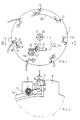
- a folding cylinder which essentially and in a known manner, as shown schematically, has a cylinder body 2, which has a shaft 3, which is mounted in a frame, not shown, in the frame of a printing press.
- the two ends of the cylinder body 2 receive a corresponding disc-shaped inner flange 4 and an outer flange 5.
- the pliers which are arranged uniformly over the circumference of the folding cylinder 1, are identified by 6.
- the folding pliers 6 consist of a fixed pliers part 7, which is on the inner flange 4th is arranged and from a movable pliers part 8 which is pivotally arranged at point 9 of the outer disc-shaped flanges 5.
- the pivoting of the movable pliers part 8 takes place via a drive arm 10 and a ball bearing 11 which cooperates with a cam plate 12, as indicated schematically in FIGS. 1 and 2.
- the eccentric shaft 13 for the adjustment process has an end 14 which enables the eccentric shaft 13 to rotate.
- An eccentric piece 15 is mounted in the inner flange 4 and an eccentric part 16 of the eccentric shaft 13 is mounted in the outer flange 5. With 4a and 5a continuous tie rods are marked, which connect the flanges 4 and 5 cage-like.
- a worm wheel 17 is arranged, with which a threaded spindle 18 is operatively connected, which is arranged on the output shaft 19 of a reducing drive 20.
- a drive of the Harmony Drive (USA) type is advantageously used as the reducing drive, this drive advantageously being operatively connected to a pneumatic motor 21.
- the line for the supply of compressed air is indicated schematically at 22. 23 with a reversing device is marked, which for the supply of compressed air in the line 24 or in the Line 25 is used to drive the motor 21.
- the motor 21 can be driven either in one or the other direction of rotation.
- a rotatable distributor 26 is provided on the shaft 13, which ensures the constant supply of compressed air to the lines 24 and 25 via the shaft 13, around the drive devices 21, 20 and 18, which are fixed via the part 27 on the folding cylinder 1 or are arranged on the outer flange 5 of the shaft end 14 to be supplied with compressed air.
- the eccentric shaft 13 has at its end 30 an encoder 31 for determining the respectively assumed angular position of the eccentric shaft 13.
- the encoder 31 or a similar device for determining the exact angular position of the eccentric shaft is operatively connected to an NC control device 35 via the connecting lines 32 and 33 and via a brush arrangement 34.
- the operation of the improved folding cylinder is as follows: If the pliers gap (d) is to be enlarged or reduced, it is sufficient to drive the motor 21 in one or the other direction of rotation via a control switch 23. There is a corresponding rotary movement of the eccentric shaft 13, which is responsible for the adjustment process. So there can be a rotary movement of the Eccentric shaft 13 can be made in one or the other direction. This rotary movement can take place with the folding cylinder rotating and with the rotary printing press running.
- the operator will therefore change the pliers gap by acting on the control switch 23 and by inspecting the folding process by checking the folded sheets.
- the NC control unit 35 acts directly on the motor 21 or on the control switch 23 with the aid of the encoder 31.
- the adjustment device described is advantageously equipped with a pneumatic motor which is equipped with a reduction gear consisting of worm wheel and threaded spindle.
- a pneumatic motor which is equipped with a reduction gear consisting of worm wheel and threaded spindle.
- you can too electric drives are provided for the adjustment process of the gap width, also in this case the output can take place with a gear mechanism which is in operative connection with the protruding end 14 of the eccentric shaft 13.
- a hydraulic device for example a piston-cylinder unit with a toothed rack, which is provided on a toothed wheel which is connected to the projecting end 14 of the eccentric shaft 13.
- the design of the eccentric shaft 13 can also be freely designed without leaving the scope of the invention.
Landscapes
- Folding Of Thin Sheet-Like Materials, Special Discharging Devices, And Others (AREA)
- Inorganic Insulating Materials (AREA)
Claims (7)
- Dispositif de pliage de feuilles pour une machine d'impression, en prévoyant un cylindre plieur avec un arbre porteur et en prévoyant des rebords en forme de disque interne et externe qui sont disposés sur les deux côtés de tête du cylindre, un rebord en forme de disque recevant les parties de pince montées fixes et l'autre rebord en forme de disque recevant les parties de pince montées mobiles des pinces de pliage, et les rebords en forme de disque étant en liaison active avec un arbre d'excentrique continu pour l'opération de réglage, cet arbre d'excentrique présentant sur un côté une pièce de raccordement faisant saillie du rebord en forme de disque, caractérisé en ce que la pièce de raccordement en saillie (14) de l'arbre d'excentrique (13) est en liaison active pour l'opération de réglage de l'espace entre-pince (d) avec un entraînement de rotation pouvant être commandé, en ce que cet entraînement de rotation (17, 18, 19, 20, 21) en vue du réglage fin peut être entraîné dans un sens de rotation ou dans l'autre (22, 23) et est fixé au cylindre plieur (1), par exemple à un rebord externe en forme de disque (5) du cylindre (1).
- Dispositif de pliage de feuilles selon la revendication 1, caractérisé en ce que le dispositif d'entraînement (17, 18, 19, 20, 21) présente une roue à denture hélicoïdale (17) qui est disposée à la pièce de raccordement en saillie (14) de l'arbre d'excentrique (13), et que cette roue à denture hélicoïdale (17) est en liaison active avec une broche filetée (18) qui est activement reliée à un moteur d'entraînement (20, 21) pouvant être commandé.
- Dispositif de pliage de feuilles selon les revendications 1 et 2, caractérisé en ce que le moteur d'entraînement (20, 21) est un moteur pneumatique dont les conduits d'entraînement (24, 25) pour la détermination de deux sens de rotation sont en liaison active par l'arbre (3) du cylindre (1) et par un distributeur d'air comprimé pneumatique (26) associé avec un commutateur de commande (23), et que le commutateur de commande (23) est en liaison active avec une source d'air comprimé (22).
- Dispositif de pliage de feuilles selon la revendication 1, caractérisé en ce que le dispositif d'entraînement (17, 18, 19, 20, 21) présente un moteur électrique qui agit par l'intermédiaire d'un engrenage réducteur inséré sur un engrenage à la pièce de raccordement de l'arbre d'excentrique (13) pour l'opération de commande.
- Dispositif de pliage de feuilles selon la revendication 1, caractérisé en ce qu'il est prévu comme dispositif d'entraînement (17, 18, 19, 20, 21) de l'arbre d'excentrique (13) une unité hydraulique, constituée d'une unité à piston et à cylindre qui agit sur une crémaillère qui agit par une roue dentée sur la pièce de raccordement en saillie de l'arbre d'excentrique pour l'opération de réglage.
- Dispositif de pliage de feuilles selon la revendication 1 à 5, caractérisé en ce qu'il est prévu sur la pièce de raccordement (14) de l'arbre d'excentrique un codeur (31) ou un appareil de détermination de position similaire pour déterminer la position angulaire de l'arbre d'excentrique (13), et le codeur est relié activement à un dispositif de commande numérique (35).
- Dispositif de pliage de feuilles selon la revendication 1 à 6, caractérisé eu ce que le dispositif d'entraînement (17, 18, 19, 20, 21) de l'arbre d'excentrique (13) pour l'opération de réglage est réalisé de telle façon qu'un flux de puissance peut être transmis seulement dans une direction, à savoir en direction vers l'arbre d'excentrique (13).
Priority Applications (1)
| Application Number | Priority Date | Filing Date | Title |
|---|---|---|---|
| AT89113278T ATE89512T1 (de) | 1988-07-29 | 1989-07-19 | Bogenfalzeinrichtung fuer eine druckmaschine. |
Applications Claiming Priority (2)
| Application Number | Priority Date | Filing Date | Title |
|---|---|---|---|
| IT2157888 | 1988-07-29 | ||
| IT8821578A IT1227324B (it) | 1988-07-29 | 1988-07-29 | Piegatrice perfezionata per segnature prodotte da una macchina da stampa. |
Publications (3)
| Publication Number | Publication Date |
|---|---|
| EP0352625A2 EP0352625A2 (fr) | 1990-01-31 |
| EP0352625A3 EP0352625A3 (fr) | 1991-01-16 |
| EP0352625B1 true EP0352625B1 (fr) | 1993-05-19 |
Family
ID=11183869
Family Applications (1)
| Application Number | Title | Priority Date | Filing Date |
|---|---|---|---|
| EP89113278A Expired - Lifetime EP0352625B1 (fr) | 1988-07-29 | 1989-07-19 | Dispositif de pliage de feuilles pour machine d'impression |
Country Status (4)
| Country | Link |
|---|---|
| EP (1) | EP0352625B1 (fr) |
| AT (1) | ATE89512T1 (fr) |
| DE (1) | DE58904400D1 (fr) |
| IT (1) | IT1227324B (fr) |
Cited By (1)
| Publication number | Priority date | Publication date | Assignee | Title |
|---|---|---|---|---|
| DE102006005121A1 (de) * | 2006-02-04 | 2007-08-09 | Peter Mayr | Falzwerk einer Druckmaschine mit mindestens einer Steuervorrichtung für Funktionseinheiten |
Families Citing this family (7)
| Publication number | Priority date | Publication date | Assignee | Title |
|---|---|---|---|---|
| DE3838314A1 (de) * | 1988-11-11 | 1990-05-17 | Koenig & Bauer Ag | Falzklappenzylinder fuer eine rollenrotationsdruckmaschine |
| DE4110035C2 (de) * | 1991-03-27 | 1995-04-13 | Roland Man Druckmasch | Vorrichtung zum Verstellen von Elementen in Falzwerkzylindern von Rotationsdruckmaschinen |
| DE4136792C2 (de) * | 1991-11-08 | 1995-07-13 | Heidelberger Druckmasch Ag | Verstelleinrichtung für falzproduktführende Zylinder in Falzapparaten an Rotationsdruckmaschinen |
| DE4337578A1 (de) * | 1993-11-04 | 1995-05-11 | Roland Man Druckmasch | Bogenführende Trommel für Druchmaschinen |
| DE4404752C2 (de) * | 1994-02-15 | 1995-11-16 | Roland Man Druckmasch | Vorrichtung zum Verstellen der Falzklappen eines Falzklappenzylinders |
| DE19522903A1 (de) * | 1995-06-23 | 1997-01-02 | Roland Man Druckmasch | Falzzylinder |
| ES2147463T3 (es) * | 1996-12-21 | 2000-09-01 | Koenig & Bauer Ag | Cilindro de aletas de plegado. |
Family Cites Families (5)
| Publication number | Priority date | Publication date | Assignee | Title |
|---|---|---|---|---|
| DE1561073B2 (de) * | 1967-04-18 | 1971-09-02 | Schnellpressenfabrik Koenig & Bauer AG, 8700 Wurzburg | Variabler falzapparat am rollenrotationsdruckmaschinen |
| DE2537920C3 (de) * | 1975-08-26 | 1979-07-12 | Maschinenfabrik Augsburg-Nuernberg Ag, 8900 Augsburg | Falzzylinder |
| DE3028468C1 (de) * | 1980-07-26 | 1981-12-24 | Koenig & Bauer AG, 8700 Würzburg | Kupplung fuer einen Falzapparatzylinder fuer veraenderliches Format |
| DE3217169C2 (de) * | 1982-05-07 | 1985-08-08 | Koenig & Bauer AG, 8700 Würzburg | Falzmesserzylinder |
| DE3220414C2 (de) * | 1982-05-29 | 1985-06-27 | Heidelberger Druckmaschinen Ag, 6900 Heidelberg | Vorrichtung zum Einstellen der Falzklappe eines Klappenzylinders im Falzapparat von Rotationsdruckmaschinen |
-
1988
- 1988-07-29 IT IT8821578A patent/IT1227324B/it active
-
1989
- 1989-07-19 EP EP89113278A patent/EP0352625B1/fr not_active Expired - Lifetime
- 1989-07-19 DE DE8989113278T patent/DE58904400D1/de not_active Expired - Fee Related
- 1989-07-19 AT AT89113278T patent/ATE89512T1/de not_active IP Right Cessation
Cited By (1)
| Publication number | Priority date | Publication date | Assignee | Title |
|---|---|---|---|---|
| DE102006005121A1 (de) * | 2006-02-04 | 2007-08-09 | Peter Mayr | Falzwerk einer Druckmaschine mit mindestens einer Steuervorrichtung für Funktionseinheiten |
Also Published As
| Publication number | Publication date |
|---|---|
| IT1227324B (it) | 1991-04-08 |
| DE58904400D1 (de) | 1993-06-24 |
| ATE89512T1 (de) | 1993-06-15 |
| IT8821578A0 (it) | 1988-07-29 |
| EP0352625A2 (fr) | 1990-01-31 |
| EP0352625A3 (fr) | 1991-01-16 |
Similar Documents
| Publication | Publication Date | Title |
|---|---|---|
| DE3940796C2 (fr) | ||
| EP0234456B2 (fr) | Dispositif d'impression complémentaire | |
| DE60008196T2 (de) | Vorrichtung zum auswechselbares Halten und Positionnieren von Druckzylinder in eine Offsetdruckmaschine | |
| EP0425936B1 (fr) | Dispositif pour le repérage, la fixation et la tension rapides de plaques d'impression | |
| EP0586881A2 (fr) | Machine à imprimer rotative pour bandes en particulier des bandes en papier épaisses | |
| DE8319431U1 (de) | Vorrichtung zur umstellung auf wahlweisen schoendruck oder schoen- und widerdruck einer zwischen den einzelnen druckwerken einer bogenrotationsdruckmaschine angeordneten wendeeinrichtung | |
| EP0736384B1 (fr) | Dispositif pour enclencher ou déclencher l'impression et procédé de contrÔle de ce dispositif | |
| EP0352625B1 (fr) | Dispositif de pliage de feuilles pour machine d'impression | |
| EP1099549B1 (fr) | Dispositif et procédé pour l'étaiement d'un cylindre en porte-à-faux | |
| EP0652105A1 (fr) | Cylindre de transfert de feuilles pour machine à imprimer | |
| EP0485912B1 (fr) | Palier pour cylindre de groupe d'impression | |
| EP0835754B1 (fr) | Réglage décentralisé individuel des surfaces d'appui des pinces dans les cylindres de transport de feuilles des presses rotatives | |
| DE102007009884C5 (de) | Druckmaschine | |
| EP0676284A1 (fr) | Machine d'impression flexographique en particulier pour l'impression en plusieurs couleurs | |
| DE69417352T3 (de) | Druckschaltvorrichtung für eine Bogendruckmaschine mit einer Wendeeinrichtung | |
| DE69806105T2 (de) | Abhebevorrichtung für Farbauftragswalzen in einer Druckmaschine | |
| DE1940075C3 (de) | Einrichtung an einem Druckwerk von Zeitungsdruck-Rollenrotati ons maschinen mit einer Papierriß-Überwachungsvorrichtung | |
| EP3962743B1 (fr) | Cylindre de blanchet et procédé de manipulation d'un blanchet | |
| DE4433998A1 (de) | Bogenführende Trommel für Rotationsdruckmaschinen | |
| DE102007011045B4 (de) | Druckmaschine | |
| DE19908118B4 (de) | Schneidmesserzylinder | |
| DD297117A5 (de) | Vorrichtung zur druckumstellung bei maschinenstillstand | |
| DE4434000C2 (de) | Bogenführende Trommel für Rotationsdruckmaschinen | |
| DE877903C (de) | Steuer- und Schaltvorrichtung fuer Druckmaschinen, insbesondere Zweitourenmaschinen,mit doppelter Einfaerbung der Druckform | |
| DE4223328C2 (de) | Vorrichtung zum Befestigen von Druckplatten auf dem Plattenzylinder von Druckmaschinen, insbesondere Bogenoffsetdruckmaschinen |
Legal Events
| Date | Code | Title | Description |
|---|---|---|---|
| PUAI | Public reference made under article 153(3) epc to a published international application that has entered the european phase |
Free format text: ORIGINAL CODE: 0009012 |
|
| AK | Designated contracting states |
Kind code of ref document: A2 Designated state(s): AT BE CH DE ES FR GB GR IT LI LU NL SE |
|
| PUAL | Search report despatched |
Free format text: ORIGINAL CODE: 0009013 |
|
| AK | Designated contracting states |
Kind code of ref document: A3 Designated state(s): AT BE CH DE ES FR GB GR IT LI LU NL SE |
|
| 17P | Request for examination filed |
Effective date: 19910301 |
|
| 17Q | First examination report despatched |
Effective date: 19921030 |
|
| GRAA | (expected) grant |
Free format text: ORIGINAL CODE: 0009210 |
|
| AK | Designated contracting states |
Kind code of ref document: B1 Designated state(s): AT BE CH DE ES FR GB GR IT LI LU NL SE |
|
| PG25 | Lapsed in a contracting state [announced via postgrant information from national office to epo] |
Ref country code: NL Effective date: 19930519 Ref country code: GR Free format text: LAPSE BECAUSE OF FAILURE TO SUBMIT A TRANSLATION OF THE DESCRIPTION OR TO PAY THE FEE WITHIN THE PRESCRIBED TIME-LIMIT Effective date: 19930519 Ref country code: SE Effective date: 19930519 Ref country code: ES Free format text: THE PATENT HAS BEEN ANNULLED BY A DECISION OF A NATIONAL AUTHORITY Effective date: 19930519 Ref country code: BE Effective date: 19930519 |
|
| REF | Corresponds to: |
Ref document number: 89512 Country of ref document: AT Date of ref document: 19930615 Kind code of ref document: T |
|
| GBT | Gb: translation of ep patent filed (gb section 77(6)(a)/1977) |
Effective date: 19930519 |
|
| REF | Corresponds to: |
Ref document number: 58904400 Country of ref document: DE Date of ref document: 19930624 |
|
| PGFP | Annual fee paid to national office [announced via postgrant information from national office to epo] |
Ref country code: GB Payment date: 19930625 Year of fee payment: 5 |
|
| ITF | It: translation for a ep patent filed | ||
| PG25 | Lapsed in a contracting state [announced via postgrant information from national office to epo] |
Ref country code: AT Effective date: 19930719 |
|
| PGFP | Annual fee paid to national office [announced via postgrant information from national office to epo] |
Ref country code: FR Payment date: 19930721 Year of fee payment: 5 |
|
| PG25 | Lapsed in a contracting state [announced via postgrant information from national office to epo] |
Ref country code: LI Effective date: 19930731 Ref country code: CH Effective date: 19930731 Ref country code: LU Free format text: LAPSE BECAUSE OF NON-PAYMENT OF DUE FEES Effective date: 19930731 |
|
| ET | Fr: translation filed | ||
| NLV1 | Nl: lapsed or annulled due to failure to fulfill the requirements of art. 29p and 29m of the patents act | ||
| PLBE | No opposition filed within time limit |
Free format text: ORIGINAL CODE: 0009261 |
|
| STAA | Information on the status of an ep patent application or granted ep patent |
Free format text: STATUS: NO OPPOSITION FILED WITHIN TIME LIMIT |
|
| REG | Reference to a national code |
Ref country code: CH Ref legal event code: PL |
|
| 26N | No opposition filed | ||
| PG25 | Lapsed in a contracting state [announced via postgrant information from national office to epo] |
Ref country code: GB Effective date: 19940719 |
|
| GBPC | Gb: european patent ceased through non-payment of renewal fee |
Effective date: 19940719 |
|
| PG25 | Lapsed in a contracting state [announced via postgrant information from national office to epo] |
Ref country code: FR Effective date: 19950331 |
|
| REG | Reference to a national code |
Ref country code: FR Ref legal event code: ST |
|
| PGFP | Annual fee paid to national office [announced via postgrant information from national office to epo] |
Ref country code: DE Payment date: 20070820 Year of fee payment: 19 |
|
| PGFP | Annual fee paid to national office [announced via postgrant information from national office to epo] |
Ref country code: IT Payment date: 20070725 Year of fee payment: 19 |
|
| PG25 | Lapsed in a contracting state [announced via postgrant information from national office to epo] |
Ref country code: DE Free format text: LAPSE BECAUSE OF NON-PAYMENT OF DUE FEES Effective date: 20090203 |
|
| PG25 | Lapsed in a contracting state [announced via postgrant information from national office to epo] |
Ref country code: IT Free format text: LAPSE BECAUSE OF NON-PAYMENT OF DUE FEES Effective date: 20080719 |