EP0349971B1 - Assemblage pour les bras de flèche d'un chargeur - Google Patents
Assemblage pour les bras de flèche d'un chargeur Download PDFInfo
- Publication number
- EP0349971B1 EP0349971B1 EP89112175A EP89112175A EP0349971B1 EP 0349971 B1 EP0349971 B1 EP 0349971B1 EP 89112175 A EP89112175 A EP 89112175A EP 89112175 A EP89112175 A EP 89112175A EP 0349971 B1 EP0349971 B1 EP 0349971B1
- Authority
- EP
- European Patent Office
- Prior art keywords
- tubular portion
- lifting
- rigid tubular
- tube
- arms
- Prior art date
- Legal status (The legal status is an assumption and is not a legal conclusion. Google has not performed a legal analysis and makes no representation as to the accuracy of the status listed.)
- Expired - Lifetime
Links
- 230000006641 stabilisation Effects 0.000 description 8
- 238000011105 stabilization Methods 0.000 description 8
- 238000010276 construction Methods 0.000 description 7
- 230000000712 assembly Effects 0.000 description 3
- 238000000429 assembly Methods 0.000 description 3
- 230000007547 defect Effects 0.000 description 2
- 238000011161 development Methods 0.000 description 2
- 230000018109 developmental process Effects 0.000 description 2
- 230000000087 stabilizing effect Effects 0.000 description 2
- 238000003466 welding Methods 0.000 description 2
- 238000009412 basement excavation Methods 0.000 description 1
- 238000004519 manufacturing process Methods 0.000 description 1
Images

Classifications
-
- E—FIXED CONSTRUCTIONS
- E02—HYDRAULIC ENGINEERING; FOUNDATIONS; SOIL SHIFTING
- E02F—DREDGING; SOIL-SHIFTING
- E02F3/00—Dredgers; Soil-shifting machines
- E02F3/04—Dredgers; Soil-shifting machines mechanically-driven
- E02F3/627—Devices to connect beams or arms to tractors or similar self-propelled machines, e.g. drives therefor
-
- E—FIXED CONSTRUCTIONS
- E02—HYDRAULIC ENGINEERING; FOUNDATIONS; SOIL SHIFTING
- E02F—DREDGING; SOIL-SHIFTING
- E02F3/00—Dredgers; Soil-shifting machines
- E02F3/04—Dredgers; Soil-shifting machines mechanically-driven
- E02F3/28—Dredgers; Soil-shifting machines mechanically-driven with digging tools mounted on a dipper- or bucket-arm, i.e. there is either one arm or a pair of arms, e.g. dippers, buckets
- E02F3/34—Dredgers; Soil-shifting machines mechanically-driven with digging tools mounted on a dipper- or bucket-arm, i.e. there is either one arm or a pair of arms, e.g. dippers, buckets with bucket-arms, i.e. a pair of arms, e.g. manufacturing processes, form, geometry, material of bucket-arms directly pivoted on the frames of tractors or self-propelled machines
-
- E—FIXED CONSTRUCTIONS
- E02—HYDRAULIC ENGINEERING; FOUNDATIONS; SOIL SHIFTING
- E02F—DREDGING; SOIL-SHIFTING
- E02F3/00—Dredgers; Soil-shifting machines
- E02F3/04—Dredgers; Soil-shifting machines mechanically-driven
- E02F3/28—Dredgers; Soil-shifting machines mechanically-driven with digging tools mounted on a dipper- or bucket-arm, i.e. there is either one arm or a pair of arms, e.g. dippers, buckets
- E02F3/36—Component parts
- E02F3/38—Cantilever beams, i.e. booms;, e.g. manufacturing processes, forms, geometry or materials used for booms; Dipper-arms, e.g. manufacturing processes, forms, geometry or materials used for dipper-arms; Bucket-arms
-
- Y—GENERAL TAGGING OF NEW TECHNOLOGICAL DEVELOPMENTS; GENERAL TAGGING OF CROSS-SECTIONAL TECHNOLOGIES SPANNING OVER SEVERAL SECTIONS OF THE IPC; TECHNICAL SUBJECTS COVERED BY FORMER USPC CROSS-REFERENCE ART COLLECTIONS [XRACs] AND DIGESTS
- Y10—TECHNICAL SUBJECTS COVERED BY FORMER USPC
- Y10T—TECHNICAL SUBJECTS COVERED BY FORMER US CLASSIFICATION
- Y10T403/00—Joints and connections
- Y10T403/33—Transverse rod to spaced plate surfaces
-
- Y—GENERAL TAGGING OF NEW TECHNOLOGICAL DEVELOPMENTS; GENERAL TAGGING OF CROSS-SECTIONAL TECHNOLOGIES SPANNING OVER SEVERAL SECTIONS OF THE IPC; TECHNICAL SUBJECTS COVERED BY FORMER USPC CROSS-REFERENCE ART COLLECTIONS [XRACs] AND DIGESTS
- Y10—TECHNICAL SUBJECTS COVERED BY FORMER USPC
- Y10T—TECHNICAL SUBJECTS COVERED BY FORMER US CLASSIFICATION
- Y10T403/00—Joints and connections
- Y10T403/70—Interfitted members
- Y10T403/7075—Interfitted members including discrete retainer
- Y10T403/7077—Interfitted members including discrete retainer for telescoping members
Definitions
- the invention relates to a lifting arm arrangement for a driven loading device with a pair of spaced, longitudinally aligned lifting arms, each containing a substantially tubular part with spaced inner and outer vertical walls, and with a twisting tube arrangement which extends between the two lifting arms and connects them together to increase the resilience of the overall arrangement.
- Powered loaders are often attached to tractors and include a pair of lifting arms that are pivotable about their rear ends and have an arrangement at their front ends suitable for receiving a loading shovel.
- the lifting arms are typically interconnected in front of the tractor by various types of arrangements that extend between the arms and serve to stabilize the entire structure. Such stabilization is necessary in order to counteract the twisting or torsional forces which occur on each arm and which occur during excavation or shoveling or when loads are distributed unevenly on the shovel.
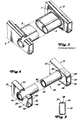
- FIG. 2 An example of such a stabilization arrangement, in which a single cross tube is used, can be found in US-A-3,254,780. It is shown in part in Fig. 2 of the accompanying drawing.
- This arrangement contains a tube which is provided with the reference number 1 and is attached between two lifting arms 2.
- the tube 1 extends through the lifting arms 2 and is welded to both of its inner and outer vertical surfaces at 3 and 4.
- This lifting arm cross tube assembly has been used extensively by Deere & Company and others for some time and has been found to be very useful for reducing the torsional forces that occur between the driven loading arms.
- the object to be achieved with the invention is seen in providing a new, improved, economical cross-tube stabilization construction which is suitable for counteracting the twists between the lifting arms and for minimizing the weld defects and tube deformations by reducing the torsional twists occurring on the tube .
- the torsional forces occurring on a loading arm are to be distributed more evenly to the opposite vertical sides of this lifting arm arrangement and furthermore also to be distributed more evenly between the opposite, vertical, outer surfaces of the box-shaped lifting arm construction by the torque tube.
- the stabilization assemblies mentioned above approximately 90% of the forces acting on the loading assembly and transmitted to the stabilization assembly are absorbed by the inner vertical surfaces of the lifting arms at the location where the stabilization assembly is connected to the arm . Only 10% was absorbed by the outer vertical lift arm surfaces at the point where the stabilization assembly was connected to the arm.
- the tube modified according to FIG. 3 with its U-shaped stiffening part and the plates connecting the stiffening part with the arms provides a stiffer connection between the arms, the force distribution on this lifting arm arrangement remains essentially the same as in the arrangement according to FIG. 2.
- the twist tube arrangement contains a first rigid tubular part and a second rigid tubular part, which are extend between the two lifting arms and the opposite ends of which extend through recesses in the spaced inner and outer vertical walls of the lifting arms, that the second rigid tubular part is held within the first rigid tubular part, that the first rigid tubular part with both the inner and is also welded to the outer wall of each of the lifting arms and that the second rigid tubular member is welded to the end portions of the first rigid tubular member.
- the outer tube extends through both vertical walls of each lifting arm and is welded to both the inside and the outside of the vertical surfaces of the lifting arms.
- the inner cross tube is welded to the larger cross tube, but only at the outer end of the larger cross tube.
- the thickness of the outer wall be made thinner and the thickness of the inner wall thicker.
- the exact dimensions and ratios depend on the dimension of the lifting arm, cross tube thickness and the relative distance.
- the loading device 10 is carried by an agricultural tractor 12 and extends forward.
- the loading device 10 contains a pair of upright posts or columns 14 which are attached to a laterally projecting frame part 16 by means of a bearing surface, the frame parts 16 in turn being carried on both sides of the tractor 12 by its main frame.
- the attachment of the charging device 10 is conventional and is therefore not described in detail here.
- the loader includes a boom in the form of two lifting arm assemblies 18 that extend forward from a transverse horizontal rear pivot axis 20 and are carried by the upright posts 14.
- the lifting arms 18 protrude beyond the front of the tractor 12 and typically carry a bucket 22 or other tool.
- the blade 22 is pivotally connected to the lifting arms 18 and can be tilted by the cylinder 24.
- the lifting arms 18 are pivoted about their rear axis of rotation 20 by extending or retracting lifting cylinders 26.
- the lifting cylinders 26 are anchored to the posts 14 with their rear ends and to the lifting arms 18 with their front ends.
- the lifting arms 18 are connected in their front region by a double-walled torsion tube, which is given the reference number 28, in order to stabilize them and to withstand torsional forces which originate from one arm 18 or from both arms 18.
- a preferred embodiment of a double-walled rotating tube and a lifting arm arrangement according to the present invention is shown in a sectional perspective in FIG. 4, in which the right and left lifting arm arrangements 18 are only shown in part.
- the double-walled rotating tube 28 connects the two lifting arm assemblies 18 to one another.
- the twisting tube 28 consists of an outer tube 30, which is arranged between the lifting arms 18 and extends through openings cut, drilled, or otherwise recessed in the two vertical walls 32, 34 of each of the lift arms 18.
- the outer tube 30 is welded to 36 and 38 where it forms connecting lines with each of the vertical walls 32 and 34 of both lifting arms 18.
- a second twist tube or inner twist tube 40 is arranged within the twist tube 30.
- This second twist tube 40 is welded to the outer tube 30 at 42 where its outer end meets the outer end of the outer tube 30. Even if, in the preferred embodiment of the invention shown, the weld seam lies within the outer tube 30, the inner tube 40 can also extend beyond the end of the outer tube 30, the weld seam 42 then lying on the outer surface of the inner tube 40 and this connects to the outer tube 30.
- FIG. 4 While various means and constructions can be used to form the box-shaped arrangement of each of the lifting arms 18, a preferred embodiment according to FIG. 4 is composed of two U-shaped channels 44 and 46, the legs 48 of which overlap and are welded together at 50 .
- An alternative embodiment for a lifting arm 18 is shown in FIG. 5. It consists of a single part 52, the legs 54 and 56 are bent so that they collide. The colliding leg portions 54 and 56 are welded together as shown at 58.
Landscapes
- Engineering & Computer Science (AREA)
- Mechanical Engineering (AREA)
- Mining & Mineral Resources (AREA)
- Civil Engineering (AREA)
- General Engineering & Computer Science (AREA)
- Structural Engineering (AREA)
- Agricultural Machines (AREA)
Claims (3)
- Ensemble de bras de levage pour un équipement de chargement mécanique (10) comportant une paire de bras de levage (18), mutuellement distants et orientés en direction longitudinale, qui comprennent chacun une partie sensiblement tubulaire présentant des parois verticales intérieure et extérieure mutuellement distantes (32, 34), et comportant un ensemble de tube de torsion qui s'étend entre les deux bras de levage (18) et les relie l'un à l'autre, caractérisé en ce que l'ensemble de tube de torsion comprend une première partie tubulaire rigide (30) et une seconde partie tubulaire rigide (40), qui s'étendent entre les deux bras de levage (18) et dont les extrémités opposées traversent des évidements pratiqués dans les parois verticales intérieure et extérieure mutuellement distantes (32, 34) des bras de levage (18), en ce que la seconde partie tubulaire rigide (40) est maintenue à l'intérieur de la première partie tubulaire rigide (30), en ce que la première partie tubulaire rigide (30) est assemblée par soudage tant à la paroi intérieure (32) qu'à la paroi extérieure (34) de chacun des bras de levage (18), et en ce que la seconde partie tubulaire rigide (40) est assemblée par soudage aux régions terminales de la première partie tubulaire rigide (30).
- Ensemble de bras de levage selon la revendication 1, caractérisé en ce que la partie tubulaire de chaque bras de levage (18) est constituée de deux profilés en U (44, 46), dont les branches (48) se recouvrent mutuellement et sont assemblées par soudage.
- Ensemble de bras de levage selon la revendication 1, caractérisé en ce que la partie tubulaire de chaque bras de levage (18) est constituée d'un profilé en U (52), dans lequel des régions libres respectives (54, 56) des branches sont recourbées l'une vers l'autre, de sorte qu'elles forment un profilé en caisson, et en ce que les extrémités libres des branches sont assemblées par soudage sur leur ligne de contact (58).
Applications Claiming Priority (2)
| Application Number | Priority Date | Filing Date | Title |
|---|---|---|---|
| US216060 | 1988-07-07 | ||
| US07/216,060 US4904151A (en) | 1988-07-07 | 1988-07-07 | Loader lift arm structure |
Publications (2)
| Publication Number | Publication Date |
|---|---|
| EP0349971A1 EP0349971A1 (fr) | 1990-01-10 |
| EP0349971B1 true EP0349971B1 (fr) | 1992-09-30 |
Family
ID=22805507
Family Applications (1)
| Application Number | Title | Priority Date | Filing Date |
|---|---|---|---|
| EP89112175A Expired - Lifetime EP0349971B1 (fr) | 1988-07-07 | 1989-07-04 | Assemblage pour les bras de flèche d'un chargeur |
Country Status (4)
| Country | Link |
|---|---|
| US (1) | US4904151A (fr) |
| EP (1) | EP0349971B1 (fr) |
| CA (1) | CA1319344C (fr) |
| DE (1) | DE58902359D1 (fr) |
Families Citing this family (19)
| Publication number | Priority date | Publication date | Assignee | Title |
|---|---|---|---|---|
| US4984958A (en) * | 1989-10-31 | 1991-01-15 | Deere & Company | Carrier frame for a quick coupler |
| US4973214A (en) * | 1990-05-07 | 1990-11-27 | J. I. Case Company | Lift arm structure for front-end loaders |
| US6106217A (en) * | 1998-08-14 | 2000-08-22 | Caterpillar Inc. | Lift arm arrangement of a construction machine |
| US6572323B2 (en) | 2000-12-29 | 2003-06-03 | Case Corporation | Lift arm structure for a work vehicle |
| US6799936B2 (en) * | 2001-10-19 | 2004-10-05 | Deere & Company | Tower and boom structure for loader bucket |
| US6698114B2 (en) | 2001-11-01 | 2004-03-02 | Clark Equipment Company | Lift arm support and storage construction for small loader |
| US6695568B2 (en) | 2001-11-01 | 2004-02-24 | Clark Equipment Company | Low profile lift arm for small skid steer loader |
| WO2003038199A1 (fr) * | 2001-11-01 | 2003-05-08 | Clark Equipment Company | Support de bras de levage pour petite chargeuse et configuration de rangement |
| GB2399836B (en) * | 2003-03-27 | 2005-09-28 | Bamford Excavators Ltd | Earthmoving blade and mounting assembly |
| AT502507B1 (de) * | 2005-09-19 | 2007-04-15 | Hauer Franz | Schwinge für ein mit einem arbeitsgerät ausgebildetes fahrzeug, insbesondere für einen traktor |
| US8631580B2 (en) | 2010-06-04 | 2014-01-21 | Caterpillar Inc. | Lift arm assembly |
| US9303383B2 (en) * | 2012-07-06 | 2016-04-05 | Caterpillar Inc. | Lift arm cross member |
| US9015968B2 (en) * | 2012-07-06 | 2015-04-28 | Caterpillar Inc. | Thumb for an excavator machine with structure support |
| DE102013222165A1 (de) * | 2013-10-01 | 2015-04-02 | Deere & Company | Frontladeranordnung |
| KR102575850B1 (ko) | 2017-04-19 | 2023-09-06 | 클라크 이큅먼트 컴파니 | 동력기계용 로더 리프트 암 조립체 |
| USD908741S1 (en) * | 2017-09-22 | 2021-01-26 | Deere & Company | Loader boom cross member |
| US10662609B2 (en) * | 2018-04-11 | 2020-05-26 | Deere & Company | Hybrid loader boom arm assembly |
| US10822768B2 (en) * | 2018-04-11 | 2020-11-03 | Deere & Company | Hybrid loader boom arm assembly |
| USD861044S1 (en) * | 2018-06-28 | 2019-09-24 | Deere & Company | Cast cross tube for production class loader boom |
Family Cites Families (12)
| Publication number | Priority date | Publication date | Assignee | Title |
|---|---|---|---|---|
| US1575208A (en) * | 1922-05-08 | 1926-03-02 | Fredrick L Jacobs | Metal ladder |
| US2610754A (en) * | 1949-10-20 | 1952-09-16 | Leo A Inskeep | Dipper handle |
| US3254780A (en) * | 1964-09-24 | 1966-06-07 | Deere & Co | Lift arm structure for power loaders |
| AT268062B (de) * | 1966-11-28 | 1969-01-27 | Heinrich Zenhaeusern | Steigeinrichtung |
| GB1201820A (en) * | 1967-10-25 | 1970-08-12 | George Molyneux | Improvements in or relating to casings for joists, columns and other structural members |
| US4098350A (en) * | 1977-01-13 | 1978-07-04 | Caterpillar Tractor Co. | Bulldozer blade push arms |
| FR2379657A1 (fr) * | 1977-02-02 | 1978-09-01 | Int Harvester Co | Fleche basculante pour chargeur monte sur un tracteur |
| US4155470A (en) * | 1978-02-01 | 1979-05-22 | International Harvester Company | Strain reducing transfer member |
| SU738975A1 (ru) * | 1979-03-20 | 1980-06-05 | Государственный проектно-конструкторский и экспериментальный институт угольного машиностроения | Ковш погрузочной машины |
| US4538955A (en) * | 1983-10-31 | 1985-09-03 | Westendorf Mfg. Co., Ltd. | Adjustable tower for front end tractor loaders |
| US4576543A (en) * | 1983-11-07 | 1986-03-18 | Kmw Products Limited | Knock-down construction for front end loader |
| FR2572474A1 (fr) * | 1984-10-30 | 1986-05-02 | Gubri Sa Ets L | Piece, ligne et procede d'assemblage d'echelles. |
-
1988
- 1988-07-07 US US07/216,060 patent/US4904151A/en not_active Expired - Fee Related
-
1989
- 1989-06-21 CA CA000603537A patent/CA1319344C/fr not_active Expired - Fee Related
- 1989-07-04 DE DE8989112175T patent/DE58902359D1/de not_active Expired - Lifetime
- 1989-07-04 EP EP89112175A patent/EP0349971B1/fr not_active Expired - Lifetime
Also Published As
| Publication number | Publication date |
|---|---|
| EP0349971A1 (fr) | 1990-01-10 |
| DE58902359D1 (de) | 1992-11-05 |
| CA1319344C (fr) | 1993-06-22 |
| US4904151A (en) | 1990-02-27 |
Similar Documents
| Publication | Publication Date | Title |
|---|---|---|
| EP0349971B1 (fr) | Assemblage pour les bras de flèche d'un chargeur | |
| DE2409941C3 (de) | Fahrzeugrahmen für Erdbewegungsfahrzeuge | |
| DE2521805A1 (de) | Ausleger | |
| DE2616859A1 (de) | Teleskop-ausleger | |
| DE3332919C2 (fr) | ||
| EP0538721A1 (fr) | Châssis pour véhicules chenillés | |
| DE10252616A1 (de) | Hinterradaufhängungsverbindungsteilaufbau unter einem Fahrzeugbogen | |
| DE2758929A1 (de) | Hubarmanordnung | |
| DE2831565C2 (de) | Querträgeranordnung | |
| DE3423415C2 (fr) | ||
| DE2827283A1 (de) | Traegeranordnung | |
| DE2406342B2 (de) | Scherenhebevorrichtung, insbesondere für Kippfahrzeuge | |
| DE2714028A1 (de) | Rahmen zum anbau eines arbeitsgeraetes, insbesondere eines hecktiefloeffels, an einem fahrzeug, wie z.b. traktor o.dgl. | |
| EP2766245B1 (fr) | Châssis auxiliaire pour véhicules automobiles | |
| DE2420889A1 (de) | Kraftfahrzeughinterachse mit laengslenkern und einer die laengslenker verbindenden, biegesteifen und drillweichen querstrebe | |
| DE60118709T2 (de) | Ladevorrichtung | |
| DE112020002034T5 (de) | Rahmen einer baumaschine | |
| DE2557161A1 (de) | Schildausbaugestell | |
| DE2011410A1 (de) | Mit Antriebsmotor versehener Fahrgestellrahmen, insbesondere für Kranfahrzeuge | |
| DE2415107C3 (de) | Lenkbares Selbstfahr-Ladegerat | |
| DE2658214A1 (de) | Stabilisierungsbaugruppe fuer die geraetetragkonstruktion von zugmaschinen o.dgl. | |
| DE2905528A1 (de) | Achsschenkelgelenktes kraftfahrzeug | |
| DE1780204A1 (de) | Hilfsrahmen fuer Fahrzeuge,insbesondere Kraftfahrzeuge | |
| DE3341614C2 (de) | Schaufellader mit einer Schaufelkippvorrichtung | |
| DE2023142B2 (de) | Ausleger fuer krane schaufelbagger od dgl |
Legal Events
| Date | Code | Title | Description |
|---|---|---|---|
| PUAI | Public reference made under article 153(3) epc to a published international application that has entered the european phase |
Free format text: ORIGINAL CODE: 0009012 |
|
| AK | Designated contracting states |
Kind code of ref document: A1 Designated state(s): BE DE FR GB NL SE |
|
| 17P | Request for examination filed |
Effective date: 19900530 |
|
| 17Q | First examination report despatched |
Effective date: 19911014 |
|
| GRAA | (expected) grant |
Free format text: ORIGINAL CODE: 0009210 |
|
| AK | Designated contracting states |
Kind code of ref document: B1 Designated state(s): BE DE FR GB NL SE |
|
| GBT | Gb: translation of ep patent filed (gb section 77(6)(a)/1977) | ||
| REF | Corresponds to: |
Ref document number: 58902359 Country of ref document: DE Date of ref document: 19921105 |
|
| ET | Fr: translation filed | ||
| PLBE | No opposition filed within time limit |
Free format text: ORIGINAL CODE: 0009261 |
|
| STAA | Information on the status of an ep patent application or granted ep patent |
Free format text: STATUS: NO OPPOSITION FILED WITHIN TIME LIMIT |
|
| 26N | No opposition filed | ||
| EAL | Se: european patent in force in sweden |
Ref document number: 89112175.8 |
|
| REG | Reference to a national code |
Ref country code: GB Ref legal event code: IF02 |
|
| PGFP | Annual fee paid to national office [announced via postgrant information from national office to epo] |
Ref country code: NL Payment date: 20050616 Year of fee payment: 17 |
|
| PGFP | Annual fee paid to national office [announced via postgrant information from national office to epo] |
Ref country code: GB Payment date: 20050629 Year of fee payment: 17 |
|
| PGFP | Annual fee paid to national office [announced via postgrant information from national office to epo] |
Ref country code: FR Payment date: 20050718 Year of fee payment: 17 |
|
| PGFP | Annual fee paid to national office [announced via postgrant information from national office to epo] |
Ref country code: SE Payment date: 20050720 Year of fee payment: 17 |
|
| PGFP | Annual fee paid to national office [announced via postgrant information from national office to epo] |
Ref country code: DE Payment date: 20050731 Year of fee payment: 17 |
|
| PGFP | Annual fee paid to national office [announced via postgrant information from national office to epo] |
Ref country code: BE Payment date: 20050819 Year of fee payment: 17 |
|
| PG25 | Lapsed in a contracting state [announced via postgrant information from national office to epo] |
Ref country code: GB Free format text: LAPSE BECAUSE OF NON-PAYMENT OF DUE FEES Effective date: 20060704 |
|
| PG25 | Lapsed in a contracting state [announced via postgrant information from national office to epo] |
Ref country code: SE Free format text: LAPSE BECAUSE OF NON-PAYMENT OF DUE FEES Effective date: 20060705 |
|
| PG25 | Lapsed in a contracting state [announced via postgrant information from national office to epo] |
Ref country code: BE Free format text: LAPSE BECAUSE OF NON-PAYMENT OF DUE FEES Effective date: 20060731 |
|
| PG25 | Lapsed in a contracting state [announced via postgrant information from national office to epo] |
Ref country code: NL Free format text: LAPSE BECAUSE OF NON-PAYMENT OF DUE FEES Effective date: 20070201 Ref country code: DE Free format text: LAPSE BECAUSE OF NON-PAYMENT OF DUE FEES Effective date: 20070201 |
|
| EUG | Se: european patent has lapsed | ||
| GBPC | Gb: european patent ceased through non-payment of renewal fee |
Effective date: 20060704 |
|
| NLV4 | Nl: lapsed or anulled due to non-payment of the annual fee |
Effective date: 20070201 |
|
| REG | Reference to a national code |
Ref country code: FR Ref legal event code: ST Effective date: 20070330 |
|
| BERE | Be: lapsed |
Owner name: *DEERE & CY Effective date: 20060731 |
|
| PG25 | Lapsed in a contracting state [announced via postgrant information from national office to epo] |
Ref country code: FR Free format text: LAPSE BECAUSE OF NON-PAYMENT OF DUE FEES Effective date: 20060731 |