EP0349837A2 - Elektronische Schaltung mit einer Schutzeinrichtung gegen Spannungsschwankungen der Versorgungsbatterie - Google Patents
Elektronische Schaltung mit einer Schutzeinrichtung gegen Spannungsschwankungen der Versorgungsbatterie Download PDFInfo
- Publication number
- EP0349837A2 EP0349837A2 EP89111330A EP89111330A EP0349837A2 EP 0349837 A2 EP0349837 A2 EP 0349837A2 EP 89111330 A EP89111330 A EP 89111330A EP 89111330 A EP89111330 A EP 89111330A EP 0349837 A2 EP0349837 A2 EP 0349837A2
- Authority
- EP
- European Patent Office
- Prior art keywords
- transistor
- protection device
- circuit
- electronic circuit
- pole
- Prior art date
- Legal status (The legal status is an assumption and is not a legal conclusion. Google has not performed a legal analysis and makes no representation as to the accuracy of the status listed.)
- Granted
Links
- 238000004519 manufacturing process Methods 0.000 description 3
- 238000010586 diagram Methods 0.000 description 1
Images
Classifications
-
- H—ELECTRICITY
- H02—GENERATION; CONVERSION OR DISTRIBUTION OF ELECTRIC POWER
- H02H—EMERGENCY PROTECTIVE CIRCUIT ARRANGEMENTS
- H02H9/00—Emergency protective circuit arrangements for limiting excess current or voltage without disconnection
- H02H9/04—Emergency protective circuit arrangements for limiting excess current or voltage without disconnection responsive to excess voltage
- H02H9/045—Emergency protective circuit arrangements for limiting excess current or voltage without disconnection responsive to excess voltage adapted to a particular application and not provided for elsewhere
- H02H9/046—Emergency protective circuit arrangements for limiting excess current or voltage without disconnection responsive to excess voltage adapted to a particular application and not provided for elsewhere responsive to excess voltage appearing at terminals of integrated circuits
Definitions
- This invention relates to an electronic circuit with a protection device against fluctuations in the supply battery voltage, being of a type which comprises a MOS power transistor connected between one pole of said battery and an electric load for driving said load to ground.
- the electric system distribution lines may be affected by sharp voltage fluctuations due to correspondingly sharp changes in the input current to electrical apparatus activated by the user, such as when turning on windshield wipers, air conditioners, or lights, and in relation to the line inductances.
- Another prior approach consists of connecting, between the integrated circuit and ground, a device which provides protection against said overvoltages; but this also aggravates the manufacturing costs, as well as adding to the cost of assembling the electric system to a car.
- the technical problem that underlies this invention is to provide an electronic circuit which has such structural and performance characteristics as to adequately guard from voltage fluctuations in the battery supply, thus overcoming the cited drawbacks with which the prior art is beset.
- a circuit of the kind specified above being characterized in that said device comprises a pair of Zener diodes connected to each other in a push-pull configuration between said pole and the gate electrode of said transistor.
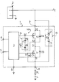
- the drawing figure shows a circuit according to the invention in diagram form.
- the numeral 1 generally and schematically denotes an electronic circuit incorporating a protection device 10 against fluctuations in the voltage from a supply battery 2.
- the circuit 1 is of the integrated type and comprises a circuit portion 3, known per se, which is connected to an input pin 4 and a pair of output pins 5 and 6, with the pin 6 connected to ground.
- the circuit 1 includes a further input pin 7 which is connected to a positive supply pole Vc of the battery 2, and a further output pin 8 which is connected to one end of a resistor RL having the other end connected to ground.
- That resistor RL is illustrative of an electric load driven to ground via the circuit 1.
- the circuit 1 includes a power transistor T1 of the enhancement, N-channel MOS type, which has its gate G1 and source S1 connected to the circuit portion 3.
- the source S1 is also connected to drive the load RL through the output pin 8.
- a second N-channel, MOS-type power transistor T2 is incorporated to the circuit 1, with its source S2 and drain D2 electrodes respectively connected to the positive pole VC, via the input pin 7, and the drain D1 of the first transistor T1.
- the gate G2 of the second transistor T2 is in turn connected to the circuit portion 3.
- An inherent diode D4 intervenes between the source S2 and the drain D2 of the second transistor T2, and is forward biased toward the source S2.
- the protection device 10 comprises a pair of diodes Z1 and Z2 of the Zener type which are connected to each other in a push-pull configuration, between the positive pole Vc and the gate G1 of the first transistor T1.
- the second transistor is also provided with a protection device 9 formed of two diodes Z3 and Z4 of the Zener type which are interconnected in a push-pull configuration, between the gate G2 and the drain D2 of the transistor T2.
- This second-mentioned device 9 has a maximum positive voltage drop Vz2 thereacross which may be of 10 Volts, for example.
- a current IL flows through the load RL which is supplied from the first transistor T1 via the second, protection transistor T2.
- drain-to-gate voltage of the second transistor T2 equals in negative value the sum of the voltage drop Vz2 plus the voltage drop Vgs2 between the gate G2 and source S2, it will be the second transistor that becomes operative as a Zener power diode.
- the provisions by this invention allow a component to be implemented in integrated circuit form which is the equivalent of a doubled power Zener capable of limiting positive or negative voltage surges to the circuit 1 without raising the overall cost of the integrated circuit.
- the circuit of this invention has a major advantage in that it can protect itself against possible overvoltages in the supply from the battery to which it is connected, while also protecting the lectric load driven by it.
- This circuit is structurally quite simple and implementable as an integrated circuit for a low manufacturing cost.
Landscapes
- Engineering & Computer Science (AREA)
- Microelectronics & Electronic Packaging (AREA)
- Emergency Protection Circuit Devices (AREA)
- Control Of Electrical Variables (AREA)
- Continuous-Control Power Sources That Use Transistors (AREA)
- Charge And Discharge Circuits For Batteries Or The Like (AREA)
- Protection Of Static Devices (AREA)
Applications Claiming Priority (2)
| Application Number | Priority Date | Filing Date | Title |
|---|---|---|---|
| IT8821234A IT1226438B (it) | 1988-07-05 | 1988-07-05 | Circuito elettronico con dispositivo di protezione da variazioni di tensione della batteria di alimentazione. |
| IT2123488 | 1988-07-05 |
Publications (3)
| Publication Number | Publication Date |
|---|---|
| EP0349837A2 true EP0349837A2 (de) | 1990-01-10 |
| EP0349837A3 EP0349837A3 (de) | 1991-03-27 |
| EP0349837B1 EP0349837B1 (de) | 1994-08-03 |
Family
ID=11178800
Family Applications (1)
| Application Number | Title | Priority Date | Filing Date |
|---|---|---|---|
| EP89111330A Expired - Lifetime EP0349837B1 (de) | 1988-07-05 | 1989-06-22 | Elektronische Schaltung mit einer Schutzeinrichtung gegen Spannungsschwankungen der Versorgungsbatterie |
Country Status (5)
| Country | Link |
|---|---|
| US (1) | US5027250A (de) |
| EP (1) | EP0349837B1 (de) |
| JP (1) | JP2938889B2 (de) |
| DE (1) | DE68917227T2 (de) |
| IT (1) | IT1226438B (de) |
Cited By (4)
| Publication number | Priority date | Publication date | Assignee | Title |
|---|---|---|---|---|
| FR2681193A1 (fr) * | 1991-09-05 | 1993-03-12 | Sgs Thomson Microelectronics | Protection des etages de sortie d'un circuit integre contre les decharges electrostatiques. |
| US5666042A (en) * | 1995-08-21 | 1997-09-09 | Delco Electronics Corp. | Switching current spike limiter for three phase coupled inductor conductive battery charger |
| FR2953078A1 (fr) * | 2009-11-24 | 2011-05-27 | Thales Sa | Dispositif de sortie de commande logique a faible tension de dechet |
| EP2023460A3 (de) * | 2007-08-07 | 2016-01-20 | Honeywell International Inc. | MEMS-basierte Batterieüberwachung |
Families Citing this family (20)
| Publication number | Priority date | Publication date | Assignee | Title |
|---|---|---|---|---|
| IT1227104B (it) * | 1988-09-27 | 1991-03-15 | Sgs Thomson Microelectronics | Circuito integrato autoprotetto da inversioni di polarita' della batteria di alimentazione |
| JPH0697739B2 (ja) * | 1989-12-21 | 1994-11-30 | 株式会社東芝 | 過電圧保護回路 |
| US5198957A (en) * | 1990-07-02 | 1993-03-30 | Motorola, Inc. | Transient protection circuit using common drain field effect transistors |
| JPH06342904A (ja) * | 1992-03-03 | 1994-12-13 | Nec Ic Microcomput Syst Ltd | 半導体集積回路装置 |
| DE69326771T2 (de) * | 1993-12-07 | 2000-03-02 | Stmicroelectronics S.R.L., Agrate Brianza | Ausgangstufe mit Transistoren von unterschiedlichem Typ |
| DE4432957C1 (de) * | 1994-09-16 | 1996-04-04 | Bosch Gmbh Robert | Schaltmittel |
| DE19803040A1 (de) * | 1997-01-31 | 1998-08-06 | Int Rectifier Corp | Leistungsschaltung |
| US5847911A (en) * | 1997-11-20 | 1998-12-08 | Trw Inc. | Self-protecting switch apparatus for controlling a heat element of a vehicle seat and a method for providing the apparatus |
| CN1078569C (zh) * | 1998-04-08 | 2002-01-30 | 张入通 | 玻璃--金属的磁脉冲热压封接工艺 |
| US6563832B1 (en) | 1998-11-30 | 2003-05-13 | Cisco Technology, Inc. | Token ring bridge distributed in a switched fabric |
| US6611410B1 (en) | 1999-12-17 | 2003-08-26 | Siemens Vdo Automotive Inc. | Positive supply lead reverse polarity protection circuit |
| DE10038323A1 (de) * | 2000-08-05 | 2002-02-14 | Philips Corp Intellectual Pty | Schaltungsanordnung |
| DE10216287A1 (de) * | 2002-04-12 | 2003-11-06 | Eupec Gmbh & Co Kg | Integrierbare Treiberschaltung zum Ansteuern eines Leistungshalbleiters |
| DE10351873B4 (de) * | 2003-11-06 | 2012-07-26 | Pilz Gmbh & Co. Kg | Vorrichtung und Verfahren zum fehlersicheren Abschalten eines induktiven Verbrauchers |
| US7119999B2 (en) * | 2004-03-20 | 2006-10-10 | Texas Instruments Incorporated | Pre-regulator with reverse current blocking |
| US20080204958A1 (en) * | 2007-02-27 | 2008-08-28 | Intersil Americas Inc. | Back-current protection circuit |
| DE112016005269T5 (de) * | 2015-11-17 | 2018-08-16 | Autonetworks Technologies, Ltd. | Umschaltschaltung und Stromversorgungssystem |
| CN109449911B (zh) * | 2018-12-26 | 2023-11-28 | 上海艾为电子技术股份有限公司 | 一种保护电路 |
| JP7294127B2 (ja) * | 2019-12-26 | 2023-06-20 | 株式会社オートネットワーク技術研究所 | 給電制御装置 |
| CN115036898A (zh) * | 2022-06-09 | 2022-09-09 | 深圳市英锐恩科技有限公司 | 一种单线通信接口的防护电路及其控制方法 |
Family Cites Families (7)
| Publication number | Priority date | Publication date | Assignee | Title |
|---|---|---|---|---|
| US3512058A (en) * | 1968-04-10 | 1970-05-12 | Rca Corp | High voltage transient protection for an insulated gate field effect transistor |
| US3723812A (en) * | 1971-03-18 | 1973-03-27 | Mc Graw Edison Co | Auxiliary means for completing current transformer secondary winding circuit |
| US3712995A (en) * | 1972-03-27 | 1973-01-23 | Rca Corp | Input transient protection for complementary insulated gate field effect transistor integrated circuit device |
| US4658203A (en) * | 1984-12-04 | 1987-04-14 | Airborne Electronics, Inc. | Voltage clamp circuit for switched inductive loads |
| US4705322A (en) * | 1985-07-05 | 1987-11-10 | American Telephone And Telegraph Company, At&T Bell Laboratories | Protection of inductive load switching transistors from inductive surge created overvoltage conditions |
| US4809122A (en) * | 1987-07-31 | 1989-02-28 | Brunswick Corporation | Self-protective fuel pump driver circuit |
| IT1226439B (it) * | 1988-07-05 | 1991-01-15 | Sgs Thomson Microelectronics | Circuito elettronico protetto da inversioni di polarita' della batteria di alimentazione. |
-
1988
- 1988-07-05 IT IT8821234A patent/IT1226438B/it active
-
1989
- 1989-06-22 DE DE68917227T patent/DE68917227T2/de not_active Expired - Fee Related
- 1989-06-22 EP EP89111330A patent/EP0349837B1/de not_active Expired - Lifetime
- 1989-06-23 US US07/370,442 patent/US5027250A/en not_active Expired - Lifetime
- 1989-07-05 JP JP1172112A patent/JP2938889B2/ja not_active Expired - Fee Related
Cited By (4)
| Publication number | Priority date | Publication date | Assignee | Title |
|---|---|---|---|---|
| FR2681193A1 (fr) * | 1991-09-05 | 1993-03-12 | Sgs Thomson Microelectronics | Protection des etages de sortie d'un circuit integre contre les decharges electrostatiques. |
| US5666042A (en) * | 1995-08-21 | 1997-09-09 | Delco Electronics Corp. | Switching current spike limiter for three phase coupled inductor conductive battery charger |
| EP2023460A3 (de) * | 2007-08-07 | 2016-01-20 | Honeywell International Inc. | MEMS-basierte Batterieüberwachung |
| FR2953078A1 (fr) * | 2009-11-24 | 2011-05-27 | Thales Sa | Dispositif de sortie de commande logique a faible tension de dechet |
Also Published As
| Publication number | Publication date |
|---|---|
| US5027250A (en) | 1991-06-25 |
| DE68917227T2 (de) | 1994-11-17 |
| JPH02119535A (ja) | 1990-05-07 |
| DE68917227D1 (de) | 1994-09-08 |
| IT8821234A0 (it) | 1988-07-05 |
| EP0349837A3 (de) | 1991-03-27 |
| EP0349837B1 (de) | 1994-08-03 |
| IT1226438B (it) | 1991-01-15 |
| JP2938889B2 (ja) | 1999-08-25 |
Similar Documents
| Publication | Publication Date | Title |
|---|---|---|
| US5027250A (en) | Electronic circuit with a protection device against fluctuations in the supply battery voltage | |
| EP0349836B1 (de) | Gegen die Polaritätsumkehr seiner Versorgungsbatterie geschützte elektronische Schaltung | |
| EP0854555B1 (de) | Schutz einer integrierten Stromversorgung | |
| US6304422B1 (en) | Polarity reversal protection circuit | |
| US4808839A (en) | Power field effect transistor driver circuit for protection from overvoltages | |
| EP0115002B1 (de) | Überspannungs-Schutzschaltung | |
| EP0736974A1 (de) | Gate-Ansteuerschaltung | |
| KR0139400B1 (ko) | 오동작 방지회로 및 보호회로 | |
| US20060023381A1 (en) | System and method for protecting a load from a voltage source | |
| US20040228053A1 (en) | Reverse battery protection circuit for power switch | |
| JPH06214666A (ja) | パワートランジスタの制御電極ディセーブル回路 | |
| JP3506489B2 (ja) | 逆バッテリ保護回路 | |
| JP2005295753A (ja) | 端子保護回路および同期整流型のスイッチング電源 | |
| US7327546B2 (en) | Power switching circuit with active clamp disconnect for load dump protection | |
| JP3642113B2 (ja) | nチャネルMOSFETの駆動回路及び電流方向切換回路 | |
| US5625518A (en) | Clamping circuit with reverse polarity protection | |
| EP0341460B1 (de) | Treiber-Schutzschaltung | |
| US6034448A (en) | Semiconductor switch | |
| US5548462A (en) | Protective circuit | |
| US10879691B2 (en) | Unlockable switch inhibitor | |
| CN112421594B (zh) | 输入防护电路和车载发电机 | |
| EP1117181B1 (de) | Spannungsschutz- und Vorspannungschaltung | |
| JPH08286771A (ja) | 半導体電子回路 | |
| US6452768B1 (en) | Circuit arrangement for protecting integrated circuits against electrostatic discharges | |
| EP0408124B1 (de) | Schutzschaltung gegen negative Überspannungen über der Stromversorgung einer integrierten Schaltung mit einer Leistungseinrichtung und seinem Regelkreis |
Legal Events
| Date | Code | Title | Description |
|---|---|---|---|
| PUAI | Public reference made under article 153(3) epc to a published international application that has entered the european phase |
Free format text: ORIGINAL CODE: 0009012 |
|
| AK | Designated contracting states |
Kind code of ref document: A2 Designated state(s): DE FR GB NL SE |
|
| PUAL | Search report despatched |
Free format text: ORIGINAL CODE: 0009013 |
|
| AK | Designated contracting states |
Kind code of ref document: A3 Designated state(s): DE FR GB NL SE |
|
| 17P | Request for examination filed |
Effective date: 19910523 |
|
| 17Q | First examination report despatched |
Effective date: 19921229 |
|
| GRAA | (expected) grant |
Free format text: ORIGINAL CODE: 0009210 |
|
| AK | Designated contracting states |
Kind code of ref document: B1 Designated state(s): DE FR GB NL SE |
|
| REF | Corresponds to: |
Ref document number: 68917227 Country of ref document: DE Date of ref document: 19940908 |
|
| ET | Fr: translation filed | ||
| EAL | Se: european patent in force in sweden |
Ref document number: 89111330.0 |
|
| PLBE | No opposition filed within time limit |
Free format text: ORIGINAL CODE: 0009261 |
|
| STAA | Information on the status of an ep patent application or granted ep patent |
Free format text: STATUS: NO OPPOSITION FILED WITHIN TIME LIMIT |
|
| 26N | No opposition filed | ||
| REG | Reference to a national code |
Ref country code: FR Ref legal event code: D6 |
|
| REG | Reference to a national code |
Ref country code: GB Ref legal event code: IF02 |
|
| PGFP | Annual fee paid to national office [announced via postgrant information from national office to epo] |
Ref country code: FR Payment date: 20020610 Year of fee payment: 14 |
|
| PGFP | Annual fee paid to national office [announced via postgrant information from national office to epo] |
Ref country code: SE Payment date: 20020611 Year of fee payment: 14 |
|
| PGFP | Annual fee paid to national office [announced via postgrant information from national office to epo] |
Ref country code: GB Payment date: 20020619 Year of fee payment: 14 |
|
| PGFP | Annual fee paid to national office [announced via postgrant information from national office to epo] |
Ref country code: DE Payment date: 20020626 Year of fee payment: 14 |
|
| PG25 | Lapsed in a contracting state [announced via postgrant information from national office to epo] |
Ref country code: GB Free format text: LAPSE BECAUSE OF NON-PAYMENT OF DUE FEES Effective date: 20030622 |
|
| PG25 | Lapsed in a contracting state [announced via postgrant information from national office to epo] |
Ref country code: SE Free format text: LAPSE BECAUSE OF NON-PAYMENT OF DUE FEES Effective date: 20030623 |
|
| PGFP | Annual fee paid to national office [announced via postgrant information from national office to epo] |
Ref country code: NL Payment date: 20030630 Year of fee payment: 15 |
|
| PG25 | Lapsed in a contracting state [announced via postgrant information from national office to epo] |
Ref country code: DE Free format text: LAPSE BECAUSE OF NON-PAYMENT OF DUE FEES Effective date: 20040101 |
|
| EUG | Se: european patent has lapsed | ||
| GBPC | Gb: european patent ceased through non-payment of renewal fee |
Effective date: 20030622 |
|
| PG25 | Lapsed in a contracting state [announced via postgrant information from national office to epo] |
Ref country code: FR Free format text: LAPSE BECAUSE OF NON-PAYMENT OF DUE FEES Effective date: 20040227 |
|
| REG | Reference to a national code |
Ref country code: FR Ref legal event code: ST |
|
| PG25 | Lapsed in a contracting state [announced via postgrant information from national office to epo] |
Ref country code: NL Free format text: LAPSE BECAUSE OF NON-PAYMENT OF DUE FEES Effective date: 20050101 |
|
| NLV4 | Nl: lapsed or anulled due to non-payment of the annual fee |
Effective date: 20050101 |