EP0348860A2 - Stanzpresse zum Lochen von grünen Plättchen mit Unterlegplättchen - Google Patents
Stanzpresse zum Lochen von grünen Plättchen mit Unterlegplättchen Download PDFInfo
- Publication number
- EP0348860A2 EP0348860A2 EP89111593A EP89111593A EP0348860A2 EP 0348860 A2 EP0348860 A2 EP 0348860A2 EP 89111593 A EP89111593 A EP 89111593A EP 89111593 A EP89111593 A EP 89111593A EP 0348860 A2 EP0348860 A2 EP 0348860A2
- Authority
- EP
- European Patent Office
- Prior art keywords
- green sheet
- punch press
- piercing
- liner
- work
- Prior art date
- Legal status (The legal status is an assumption and is not a legal conclusion. Google has not performed a legal analysis and makes no representation as to the accuracy of the status listed.)
- Granted
Links
Images


Classifications
-
- H—ELECTRICITY
- H10—SEMICONDUCTOR DEVICES; ELECTRIC SOLID-STATE DEVICES NOT OTHERWISE PROVIDED FOR
- H10P—GENERIC PROCESSES OR APPARATUS FOR THE MANUFACTURE OR TREATMENT OF DEVICES COVERED BY CLASS H10
- H10P72/00—Handling or holding of wafers, substrates or devices during manufacture or treatment thereof
- H10P72/04—Apparatus for manufacture or treatment
- H10P72/0428—Apparatus for mechanical treatment or grinding or cutting
-
- H—ELECTRICITY
- H05—ELECTRIC TECHNIQUES NOT OTHERWISE PROVIDED FOR
- H05K—PRINTED CIRCUITS; CASINGS OR CONSTRUCTIONAL DETAILS OF ELECTRIC APPARATUS; MANUFACTURE OF ASSEMBLAGES OF ELECTRICAL COMPONENTS
- H05K3/00—Apparatus or processes for manufacturing printed circuits
- H05K3/0011—Working of insulating substrates or insulating layers
- H05K3/0044—Mechanical working of the substrate, e.g. drilling or punching
- H05K3/005—Punching of holes
-
- H—ELECTRICITY
- H05—ELECTRIC TECHNIQUES NOT OTHERWISE PROVIDED FOR
- H05K—PRINTED CIRCUITS; CASINGS OR CONSTRUCTIONAL DETAILS OF ELECTRIC APPARATUS; MANUFACTURE OF ASSEMBLAGES OF ELECTRICAL COMPONENTS
- H05K1/00—Printed circuits
- H05K1/02—Details
- H05K1/03—Use of materials for the substrate
- H05K1/0306—Inorganic insulating substrates, e.g. ceramic, glass
-
- H—ELECTRICITY
- H05—ELECTRIC TECHNIQUES NOT OTHERWISE PROVIDED FOR
- H05K—PRINTED CIRCUITS; CASINGS OR CONSTRUCTIONAL DETAILS OF ELECTRIC APPARATUS; MANUFACTURE OF ASSEMBLAGES OF ELECTRICAL COMPONENTS
- H05K2203/00—Indexing scheme relating to apparatus or processes for manufacturing printed circuits covered by H05K3/00
- H05K2203/01—Tools for processing; Objects used during processing
- H05K2203/0147—Carriers and holders
- H05K2203/0156—Temporary polymeric carrier or foil, e.g. for processing or transferring
-
- Y—GENERAL TAGGING OF NEW TECHNOLOGICAL DEVELOPMENTS; GENERAL TAGGING OF CROSS-SECTIONAL TECHNOLOGIES SPANNING OVER SEVERAL SECTIONS OF THE IPC; TECHNICAL SUBJECTS COVERED BY FORMER USPC CROSS-REFERENCE ART COLLECTIONS [XRACs] AND DIGESTS
- Y10—TECHNICAL SUBJECTS COVERED BY FORMER USPC
- Y10T—TECHNICAL SUBJECTS COVERED BY FORMER US CLASSIFICATION
- Y10T83/00—Cutting
- Y10T83/647—With means to convey work relative to tool station
- Y10T83/654—With work-constraining means on work conveyor [i.e., "work-carrier"]
Definitions
- This invention relates to a punch press for piercing a ceramics type green sheet, more particularly to an improvement of punching press machine for piercing a various forms and sized perforations passing through upon its surface of the green sheet before sintering process in the art of utilizing it for IC substrate and the like.
- a green sheet is formed as a thin sheet by the so-called Doctor blade method or Calendar method, which is made from a mixture compounds of a pulverized ceramics, an organic bonding agent, a plasticizer, a solvent and the like.
- the raw sheet before sintering has a rich plasticity, flexibility and workability, therefore, it is known that it can easily cut-off, drilling, punching, bonding and the like, thus useful for IC substrate and the like pursuant to a sintering process in the art.
- a raw material of ceramic compound is coated on a tape (such as a polyester resin film and the like) uniformly with a predetermined thickness, and then dried in ordinary course.
- the ceramic sheet layer is peeled off from the tape for obtaining a green sheet slip shown as a green color namely, wherein it is passed to a piercing process by using an exclusive type punch press machine.
- the present invention therefore, has been achieved to solve the aforementioned disadvantage, it is a general object of this invention to provide a punch press enabling to pierce the green sheet together with the tape, that is, without any peeling-off the raw core of green sheet from the tape. It is a further object of this invention to provide a further improved apparatus to be obtainable a more high grade products.
- a punch press for piercing the green sheet in which comprising of: a plurality of piercing assembly consisting of a piercing punches(male) and its female dies having a various shapes and sizes applicable to IC substrate and the like in which are loaded into a punch press frame mechanism; a punch press frame mechanism with the piercing assembly therein arranged parallel to x-axis direction; a pair of green sheet webs loaded into a housing as facing each other with the punch press frame mechanism between, and an unprocessed green sheet webbed in one side is fed intermittently into an opposite web capstan in response to each shot by the punching action of punch press mechanism; a work piece feeding section provided to load a pair of the above webs in its housing so as to stretch the green sheet between both webs; and a drive mechanism provided to move the above feeding section to x-axis direction and/or y-axis direction.
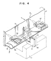
- Fig.1 as a total system of the punch press, it comprises in major of a working section(A) and a control section(B) which controls the total system.
- the working section(A) is arranged on a bed(1), which consisting of the punch press frame section(2), the feeding mechanism(3) and the mobil mechanism(4).
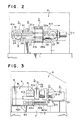
- the punch press frame section(2) is provided to perform a piercing work to the green sheet(9), which equips six units of piercing assemblies as shown in (21), (22),(23),(24),(25) and (26) which consisting of a six pieces of piercing punches(21a),(22a),(23a),(24a),(25a) and (26a) and also the same pieces of female dies(21b),(22b),23b),24b),25b) and (26b).
- the punch press frame section is arranged on the bed(1) and those piercing assemblies are arranged so as to align to x-axis direction therein. It is admitted to load a plurality of piercing assemblies into the punch press frame section.
- the punch press frame section has an adequate percussion mechanism to impact the piercing punches toward the femal dies through a slip shaped work piece between, that is, the green sheet with a liner.
- the work piece feeding section(3) is provided to hold the work piece drawn out from an web, and feeds into the punch press frame section(2), which consisting of a housing(31), a feeding motor(32) and a coiling motor(33) disposed within the housing(31) for feeding and coiling the work piece from one web to another web, a feeder shaft(34) of the feeding motor(32) and a capstan shaft(35) of the coiling motor(33) which are connected directly with those motors(32) (33) and both projected from the outer surface of housing(31), and a pair of vacuum gripper(36) (37) which are disposed with the housing(31) and between the above two shafts(34) (35).
- the work piece feeding section(3) is held with a drive mechanism(4) movably toward x-axis.
- the drive mechanism(4) is provided to move the work piece(9) to x-axis and/or y-axis through the work piece feeding section(3), which consists of a x-axis drive mechanism(41) and a y-axis drive mechanism(42).
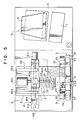
- the x-axis drive mechanism(41) is provided to move the work piece feeding section(3) toward x-axis direction, which consisting of the other housing(41a) arranged to x-axis direction, a jack-screw shaft(41b) disposed in the other housing(41a), a x-axis motor(41c) connected with the jack-screw shaft(41b) to rotate the shaft(41b) for traversing the punch press frame section(2) toward x-axis direction, and a screw cursor(41d) to engage with the jack-screw shaft(41b) for supporting the other housing(31) of the work piece feeding section(3).
- the x-axis drive mechanism(41) is arranged movably on a y-axis drive mechanism(42).
- the y-axis drive mechanism(42) is provided to move the x-axis drive mechanism(41) toward y-axis direction, which consists of a jacck-screw shaft (42b) engaging with a screw cursor(42a) supporting the other housing(41a) of the x-axis drive mechanism(41) with a y-axis motor(42c) connected with the jack-screw shaft(42b) for rotating the shaft(42b) in which the y-axis motor(42c) being fixed with the bed(1), and two pieces of guide pin(42d) (42e) which being fixed with the bed(1) to guide the other housing(41a) of the x-axis drive mechanism(41) in engaging with the other housing(41a).
- a control section(B) consists of: a console body(5) housed with a microcomputer; a display panel(6) connected with and applied on the console body(5); and an offset type microscope (8) which is disposed adjacent the punch press frame section(2) for automatically control the piercing work of punch press frame section(2).
- green sheet(9) the green sheet(9) consisting of the aforementioned ceramic compound layer(92) coated on a tape(91) with a predetermined thickness uniformly and then dried.
- the green sheet(9) is then webbed at the feeder's web shaft(34) in order to stretch the sheet(9) into the coiling shaft(35).
- the sheet(9) is held by the vacuum grippers(36) (37) so as to be tensed between both grippers(36) (37), so that it can keep its shape as a flat sheet.
- green sheet(9) consisting of 0.1mm(millimeter) of the ceramic layer (92) and 0.3mm of the polyester resin film tape, therefore, its total thickness is at 0.4mm.
- a desirable data is input into the console(5) to set up a preferable piercing position and the selection of piercing assemblies(21), (22), (23), (24), (25), and (26).
- the green sheet which is held by the vacuum grippers(36) (37) is transferred into the punch press frame section(2) by the drive mechanism(4) and held effectively.
- the piercing work is performed with various forms under the detection and control of the offset type microscope(8) fixed adjacent the punch press frame section(2).
- the console(5) According to the input data into the console(5), it is possible to feed a unprocessed blank sheet without any piercing work by an adequate drive of the feeding motor(32) and the coiling motor(33) as an optional example.
- an actuator such as an air cylinder and the like into the structure of drive mechanism(4).
- the control section(B) it is not always necessary, instead it is admitted to control manually without the control section(B) or to adopt two ways system capable to switch either of a manual operation or an automatic operation.
- the drive mechanism(4) it was referred to the x-axis mechanism(41) and y-axis mechanism(42) in the above, it is suggested to add one more necessary drive mechanism into the drive section of this punch press machine, that is, it is a z-axis drive mechanism which is capable to elevate vertically an objective section such as either of the punch press frame section or the work piece feeding section and then it is suggested to operate these three mechanisms in charge of each x, y and z-axis selectively or simultaneously.
- this z-axis drive mechanism is particularly effective for keeping its level position of the work piece into between the guide slit of piercing assemblies during their piercing works, although the feature of z-axis mechanism is not shown specially in the drawings of the disclosure.
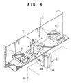
- the punch press frame section(3) is arranged fixedly on the bed(1).
- the drive mechanism(4) is a device to move the punch press frame section(2) toward x-axis direction and/or y-axis direction, which consists of the x-axis drive mechanism(41) and Y-axis drive mechanism(42).
- the x-axis drive mechanism(41) is a device to move the punch press frame mechanism(2) toward x-axis direction, which consists of the housing(41a) arranged to x-axis direction and fixed with the punch press frame section(2), the jack-screw shaft(41b) fixed in the housing(41a), the x-axis motor(41c) connected with the jack-screw shaft(41b) to rotate the shaft (41b), and the screw cursor(41d) engaged with the jack-screw shaft(41b) and fixed with the housing(41a).
- the punch press frame section(2) is moved by the drive mechanism(4) against the green sheet(9), wherein the green sheet(9) is held effectively into the punch press frame section(2).
- a necessary data of the piercing position by using the offset type microscope(8) or the selective movement of piercing assemblies such as (21),(22),(23),(24),(25) and (26) are input into the console(5) of control section(B). According to these input data, the piercing work is performed.
Landscapes
- Engineering & Computer Science (AREA)
- Manufacturing & Machinery (AREA)
- Microelectronics & Electronic Packaging (AREA)
- Perforating, Stamping-Out Or Severing By Means Other Than Cutting (AREA)
- Devices For Post-Treatments, Processing, Supply, Discharge, And Other Processes (AREA)
Applications Claiming Priority (4)
| Application Number | Priority Date | Filing Date | Title |
|---|---|---|---|
| JP16318688A JPH0747279B2 (ja) | 1988-06-29 | 1988-06-29 | セラミックグリーンシートの穿孔装置 |
| JP163186/88 | 1988-06-29 | ||
| JP163187/88 | 1988-06-29 | ||
| JP16318788A JPH0747280B2 (ja) | 1988-06-29 | 1988-06-29 | セラミックグリーンシートの穿孔装置 |
Publications (3)
| Publication Number | Publication Date |
|---|---|
| EP0348860A2 true EP0348860A2 (de) | 1990-01-03 |
| EP0348860A3 EP0348860A3 (de) | 1991-05-02 |
| EP0348860B1 EP0348860B1 (de) | 1994-04-06 |
Family
ID=26488716
Family Applications (1)
| Application Number | Title | Priority Date | Filing Date |
|---|---|---|---|
| EP19890111593 Expired - Lifetime EP0348860B1 (de) | 1988-06-29 | 1989-06-26 | Stanzpresse zum Lochen von grünen Plättchen mit Unterlegplättchen |
Country Status (3)
| Country | Link |
|---|---|
| US (1) | US4990080A (de) |
| EP (1) | EP0348860B1 (de) |
| DE (1) | DE68914343T2 (de) |
Families Citing this family (11)
| Publication number | Priority date | Publication date | Assignee | Title |
|---|---|---|---|---|
| JP2704562B2 (ja) * | 1990-07-19 | 1998-01-26 | 株式会社村田製作所 | 積層セラミックコンデンサの製造方法 |
| JP3082549B2 (ja) * | 1993-12-27 | 2000-08-28 | 株式会社村田製作所 | 支持フィルム付きセラミックグリーンシートの製造方法 |
| US5759331A (en) * | 1994-07-15 | 1998-06-02 | Paul J. Dostart | Method of ensuring conductivity in the manufacturing of a multi-layer ceramic component containing interlayer conductive-filled via holes |
| US5666838A (en) * | 1995-06-05 | 1997-09-16 | Efco, Incorporated | Forging press for use with automated multi-station transport system |
| US5772838A (en) * | 1995-09-28 | 1998-06-30 | Pacific Trinetics Corporation | Apparatus and method for making laminated electrical or electronic devices from a continuous tape coated on one side with ceramic material |
| US6045714A (en) * | 1998-04-01 | 2000-04-04 | International Business Machines Corporation | Method for forming flat surface vias in integrated circuit substrates |
| US6523596B1 (en) * | 2000-08-23 | 2003-02-25 | Wayne-Dalton Corporation | Apparatus for manufacturing a flexible curtain |
| ATE271941T1 (de) * | 2000-11-08 | 2004-08-15 | Trumpf Gmbh & Co | Werkzeugmaschine mit vorschubeinrichtung |
| US6955737B2 (en) * | 2003-06-30 | 2005-10-18 | International Business Machines Corporation | Supported greensheet structure and method in MLC processing |
| US9505504B2 (en) | 2011-02-18 | 2016-11-29 | Pouch Pac Innovations, Llc | Apparatus for the two stage filling of flexible pouches |
| US9944037B2 (en) * | 2011-05-12 | 2018-04-17 | Pouch Pac Innovations, Llc | Apparatus for simultaneously separating a plurality of pouches, transferring the pouches and method of same |
Family Cites Families (16)
| Publication number | Priority date | Publication date | Assignee | Title |
|---|---|---|---|---|
| US3097929A (en) * | 1956-04-16 | 1963-07-16 | Gladding Mcbean & Co | Method for continuous manufacture of ceramic sheathing |
| US3518756A (en) * | 1967-08-22 | 1970-07-07 | Ibm | Fabrication of multilevel ceramic,microelectronic structures |
| GB1418459A (en) * | 1971-12-29 | 1975-12-17 | Atomic Energy Authority Uk | Sintered artefacts |
| GB1432376A (en) * | 1972-09-30 | 1976-04-14 | British Aircraft Corp Ltd | Interconnectors for circuit boards |
| US3956052A (en) * | 1974-02-11 | 1976-05-11 | International Business Machines Corporation | Recessed metallurgy for dielectric substrates |
| US4106181A (en) * | 1976-08-09 | 1978-08-15 | American Safety Equipment Corporation | Quick release mechanism for oscillating saw blade |
| US4094944A (en) * | 1976-10-22 | 1978-06-13 | Owens-Corning Fiberglas Corporation | Machine for and continuous process of making molded tile |
| US4443278A (en) * | 1981-05-26 | 1984-04-17 | International Business Machines Corporation | Inspection of multilayer ceramic circuit modules by electrical inspection of green specimens |
| FR2520182A1 (fr) * | 1982-01-18 | 1983-07-22 | Bornelec Sa | Procede et dispositif automatique de lecture et de recopie de plans de percage de circuits imprimes |
| GB2130953B (en) * | 1982-11-02 | 1986-02-19 | Amada Co Ltd | Punch press |
| US4612407A (en) * | 1983-04-01 | 1986-09-16 | At&T Laboratories | Aliphatic aromatization with intemetallic Group VIII-IIIA, IVA catalyst |
| US4539058A (en) * | 1983-12-12 | 1985-09-03 | International Business Machines Corporation | Forming multilayer ceramic substrates from large area green sheets |
| JPS60228099A (ja) * | 1984-04-20 | 1985-11-13 | 株式会社日立製作所 | 打抜き加工方法 |
| US4674373A (en) * | 1984-10-16 | 1987-06-23 | Trumpf Gmbh & Co. | Method and apparatus for nibbling cutouts by rotation of tooling with cutting surfaces of different contours and tooling therefor |
| US4786342A (en) * | 1986-11-10 | 1988-11-22 | Coors Porcelain Company | Method for producing cast tape finish on a dry-pressed substrate |
| JPH08398B2 (ja) * | 1987-04-24 | 1996-01-10 | 潮工業有限会社 | 薄板状物の穿孔装置及び穿孔装置用パンチングユニツト |
-
1989
- 1989-06-23 US US07/370,874 patent/US4990080A/en not_active Expired - Lifetime
- 1989-06-26 EP EP19890111593 patent/EP0348860B1/de not_active Expired - Lifetime
- 1989-06-26 DE DE68914343T patent/DE68914343T2/de not_active Expired - Fee Related
Also Published As
| Publication number | Publication date |
|---|---|
| EP0348860A3 (de) | 1991-05-02 |
| US4990080A (en) | 1991-02-05 |
| DE68914343T2 (de) | 1994-11-03 |
| EP0348860B1 (de) | 1994-04-06 |
| DE68914343D1 (de) | 1994-05-11 |
Similar Documents
| Publication | Publication Date | Title |
|---|---|---|
| EP0348860A2 (de) | Stanzpresse zum Lochen von grünen Plättchen mit Unterlegplättchen | |
| EP1246959B1 (de) | Knopfzuführungseinrichtung mit breitekontrollfunktion und zentrierungsfunktion | |
| JPH11135985A (ja) | 電気部品供給方法および装置ならびに電気部品装着装置 | |
| JP2001062525A (ja) | 薄板型抜き装置 | |
| US5993144A (en) | Complex-type article conveying apparatus | |
| EP1524069A2 (de) | Bearbeitungzelle mit einem Roboter zum Handhaben von Werkstückträgern zwischen einem Lager und einer Maschine mittels einer Transportvorrichtung | |
| US5224250A (en) | Apparatus for manufacturing ceramic capacitors | |
| JP2689001B2 (ja) | 線材製造装置およびピン打ち装置 | |
| EP1480507B1 (de) | Halbleiter-Montageeinrichtung | |
| JP2608969B2 (ja) | スルーホール成形におけるワーク制御方法 | |
| JP3189223B2 (ja) | 打ち抜き装置におけるシート材の搬送方法 | |
| EP3401278B1 (de) | Vorrichtung zum ausziehen und verfahren zum ausziehen | |
| JP4129935B2 (ja) | テープ状物の穿孔装置 | |
| JPS63215325A (ja) | 板材の把持移送装置 | |
| JPS58132430A (ja) | 複数薄板部品の連続生産装置 | |
| JPH11245093A (ja) | 打ち抜き方法およびこの方法に用いる打ち抜き装置 | |
| JP2000246693A (ja) | テープ状物の穿孔装置 | |
| JP2811618B2 (ja) | オーリングを有するテーピング部材と該部材の取扱い方法 | |
| JP2846265B2 (ja) | ワークの打抜き装置 | |
| JP3170093B2 (ja) | パンチングマシン | |
| JPS6182791A (ja) | 保持装置 | |
| JPH0353775Y2 (de) | ||
| JP2724206B2 (ja) | プリント基板の自動ピン抜き装置 | |
| JPH07185920A (ja) | ワークの穴明け切断加工方法及び同加工ライン装置 | |
| JPH029599A (ja) | セラミックグリーンシートの穿孔装置 |
Legal Events
| Date | Code | Title | Description |
|---|---|---|---|
| PUAI | Public reference made under article 153(3) epc to a published international application that has entered the european phase |
Free format text: ORIGINAL CODE: 0009012 |
|
| AK | Designated contracting states |
Kind code of ref document: A2 Designated state(s): DE FR GB IT SE |
|
| PUAL | Search report despatched |
Free format text: ORIGINAL CODE: 0009013 |
|
| AK | Designated contracting states |
Kind code of ref document: A3 Designated state(s): DE FR GB IT SE |
|
| 17P | Request for examination filed |
Effective date: 19910823 |
|
| 17Q | First examination report despatched |
Effective date: 19920428 |
|
| GRAA | (expected) grant |
Free format text: ORIGINAL CODE: 0009210 |
|
| ITF | It: translation for a ep patent filed | ||
| AK | Designated contracting states |
Kind code of ref document: B1 Designated state(s): DE FR GB IT SE |
|
| REF | Corresponds to: |
Ref document number: 68914343 Country of ref document: DE Date of ref document: 19940511 |
|
| ET | Fr: translation filed | ||
| EAL | Se: european patent in force in sweden |
Ref document number: 89111593.3 |
|
| PLBE | No opposition filed within time limit |
Free format text: ORIGINAL CODE: 0009261 |
|
| STAA | Information on the status of an ep patent application or granted ep patent |
Free format text: STATUS: NO OPPOSITION FILED WITHIN TIME LIMIT |
|
| 26N | No opposition filed | ||
| PGFP | Annual fee paid to national office [announced via postgrant information from national office to epo] |
Ref country code: GB Payment date: 19970514 Year of fee payment: 9 |
|
| PGFP | Annual fee paid to national office [announced via postgrant information from national office to epo] |
Ref country code: SE Payment date: 19970520 Year of fee payment: 9 |
|
| PG25 | Lapsed in a contracting state [announced via postgrant information from national office to epo] |
Ref country code: GB Free format text: LAPSE BECAUSE OF NON-PAYMENT OF DUE FEES Effective date: 19980626 |
|
| PG25 | Lapsed in a contracting state [announced via postgrant information from national office to epo] |
Ref country code: SE Free format text: LAPSE BECAUSE OF NON-PAYMENT OF DUE FEES Effective date: 19980627 |
|
| GBPC | Gb: european patent ceased through non-payment of renewal fee |
Effective date: 19980626 |
|
| EUG | Se: european patent has lapsed |
Ref document number: 89111593.3 |
|
| PGFP | Annual fee paid to national office [announced via postgrant information from national office to epo] |
Ref country code: FR Payment date: 20030623 Year of fee payment: 15 |
|
| PG25 | Lapsed in a contracting state [announced via postgrant information from national office to epo] |
Ref country code: FR Free format text: LAPSE BECAUSE OF NON-PAYMENT OF DUE FEES Effective date: 20050228 |
|
| REG | Reference to a national code |
Ref country code: FR Ref legal event code: ST |
|
| PGFP | Annual fee paid to national office [announced via postgrant information from national office to epo] |
Ref country code: DE Payment date: 20050622 Year of fee payment: 17 |
|
| PGFP | Annual fee paid to national office [announced via postgrant information from national office to epo] |
Ref country code: IT Payment date: 20060630 Year of fee payment: 18 |
|
| PG25 | Lapsed in a contracting state [announced via postgrant information from national office to epo] |
Ref country code: DE Free format text: LAPSE BECAUSE OF NON-PAYMENT OF DUE FEES Effective date: 20070103 |
|
| PG25 | Lapsed in a contracting state [announced via postgrant information from national office to epo] |
Ref country code: IT Free format text: LAPSE BECAUSE OF NON-PAYMENT OF DUE FEES Effective date: 20070626 |