EP0348719B1 - Machine à écorcer - Google Patents
Machine à écorcer Download PDFInfo
- Publication number
- EP0348719B1 EP0348719B1 EP89110539A EP89110539A EP0348719B1 EP 0348719 B1 EP0348719 B1 EP 0348719B1 EP 89110539 A EP89110539 A EP 89110539A EP 89110539 A EP89110539 A EP 89110539A EP 0348719 B1 EP0348719 B1 EP 0348719B1
- Authority
- EP
- European Patent Office
- Prior art keywords
- cutter head
- peeling
- round
- peeling machine
- measuring device
- Prior art date
- Legal status (The legal status is an assumption and is not a legal conclusion. Google has not performed a legal analysis and makes no representation as to the accuracy of the status listed.)
- Expired - Lifetime
Links
- 239000000463 material Substances 0.000 claims description 19
- 238000000034 method Methods 0.000 claims description 12
- 238000004140 cleaning Methods 0.000 claims description 8
- 230000002441 reversible effect Effects 0.000 claims description 2
- 238000000605 extraction Methods 0.000 claims 1
- 238000005259 measurement Methods 0.000 description 8
- 238000005520 cutting process Methods 0.000 description 4
- 238000003780 insertion Methods 0.000 description 4
- 230000037431 insertion Effects 0.000 description 4
- 230000032258 transport Effects 0.000 description 3
- 230000000694 effects Effects 0.000 description 2
- 239000003999 initiator Substances 0.000 description 2
- 229910000831 Steel Inorganic materials 0.000 description 1
- 239000002826 coolant Substances 0.000 description 1
- 239000000498 cooling water Substances 0.000 description 1
- 238000013461 design Methods 0.000 description 1
- 238000011161 development Methods 0.000 description 1
- 230000001771 impaired effect Effects 0.000 description 1
- 239000012535 impurity Substances 0.000 description 1
- 238000003754 machining Methods 0.000 description 1
- 238000012545 processing Methods 0.000 description 1
- 239000010959 steel Substances 0.000 description 1
- 230000001960 triggered effect Effects 0.000 description 1
- 238000011144 upstream manufacturing Methods 0.000 description 1
Images
Classifications
-
- B—PERFORMING OPERATIONS; TRANSPORTING
- B23—MACHINE TOOLS; METAL-WORKING NOT OTHERWISE PROVIDED FOR
- B23B—TURNING; BORING
- B23B5/00—Turning-machines or devices specially adapted for particular work; Accessories specially adapted therefor
- B23B5/08—Turning-machines or devices specially adapted for particular work; Accessories specially adapted therefor for turning axles, bars, rods, tubes, rolls, i.e. shaft-turning lathes, roll lathes; Centreless turning
- B23B5/12—Turning-machines or devices specially adapted for particular work; Accessories specially adapted therefor for turning axles, bars, rods, tubes, rolls, i.e. shaft-turning lathes, roll lathes; Centreless turning for peeling bars or tubes by making use of cutting bits arranged around the workpiece
Definitions
- the invention relates to a peeling machine according to the preamble of claim 1 and a method for peeling round material.
- Peeling machines of this type are mainly used to produce so-called bright steel from hot-rolled round material.
- the rod-shaped round material is peeled on its cylindrical circumference by a rotating cutter head.
- the rod itself is axially guided through the peeling machine through a central hole in the cutter head and secured against unwanted rotation.
- the rotating cutter head carries 3 or more inward-facing knives that peel the bar on a helical path.
- Such peeling machines are used for wire, bars and tubes.
- the currently used peeling machines work with a slide-in device on the inlet side in front of the cutter head, which consists of two pairs of rollers, and with a tension carriage on the outlet side of the cutter head, which secures and transports the rod against twisting when the last end of the rod is peeled.
- Modern peeling machines can change the feed, the cutter head speed and the finished diameter during operation.
- a peeling machine of the type described at the outset is known from DE-OS 1 552 359.
- It has a rotating cutter head with inward-facing knives, a driven insertion unit for the round material, the insertion unit being arranged on the inlet side of the cutter head, a pull-out device on the outlet side of the cutter head and a measuring device for detecting the peeled diameter.
- the measuring device is arranged on the outlet side of the cutter head and is used for ongoing recording of the peeled finished diameter.
- a disadvantage of this peeling machine is that the peeling process cannot be automated, because the peeled rod is only measured when its end on the inlet side has left the peeling machine or the cutter head and a downstream guide for the peeled material on the outlet side.
- This presetting is necessary so that the feed rollers have the correct distance from each other and so the peeling knife can be adjusted so that the desired finished diameter is likely to be obtained.
- the peeling is not mentioned there. The peeling is used to check this presetting, especially the peeling knife.
- the invention has for its object to design and equip a peeling machine for an automatic peeling process.
- the solution to this problem is given in claim 1.
- Many peeling machines have a so-called "front guide" between the inserting device and the cutter head, which is a type of roller caliber that, particularly in the case of thin workpieces, causes the peeling material to be centered immediately in front of the cutter head and dampens the vibrations resulting from the cutting process.
- the measuring device is arranged between the driven roller table upstream of the peeling machine and the cutter head, but preferably on the inlet side of the front guide. The effect of this is that the effect of the front guide and the insertion apparatus is not impaired and that only a longitudinal section of the peeling material which is long enough for the measurement has to be peeled off.
- Measuring devices of the type mentioned in claim 3 are preferably provided since, in the absence of sensors, they have no mechanical wear. Such measuring devices also have the advantage that presetting to a diameter to be selected is not necessary. Incorrect operation when presetting the diameter measuring device cannot cause any damage to the device.
- the invention is also intended to reduce the peeling process be automated. Since modern peeling machines are operated program-controlled anyway, in a further embodiment of the invention, the peeling should also take place according to a program that can be called up from the control panel.
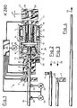
- the peeling machine consists of a slide-in unit 2, a laser measuring device 3 with an indicator 36 provided in the direction of arrow 23 on the outlet side of the laser measuring device, a compressed air cleaning device 4, a front guide 5, a cutter head 26 on a hollow shaft 6, which is in a machine frame 7 known manner in bearings 17, 18 is rotatably received, a rear guide 10, which clamps the rod on the peeled section with its rollers 16, a rear laser measuring device 11 and a clamping carriage 12 which can be moved according to arrow 27 and with its clamping jaws 19, 20 secures the rod 24 against twisting and pulls it out of the peeling machine.
- the workflow of the peeling machine 1 is determined by a control device 25 to which, inter alia, the plug-in unit 2, the inlet-side laser measuring device 3, the cleaning device 4, the servomotor for the knives 15 and the outlet-side laser measuring device 11 are connected.
- the cutter head 26 is located in an extended shoulder on the inlet-side end face of the hollow shaft 6, in which a conical sleeve 8 can be displaced in the direction of travel of the rod 24 by a servomotor 9 with the hollow shaft 6 rotating, a plurality of knife holders 14 which are supported radially on the inside of the cone of the conical sleeve 8 and which are displaced in the radial direction of the rod 24 when the conical sleeve 8 is axially displaced.
- the knives 15 on the knife holders 14 peel a layer of adjustable thickness from the rod 24 in accordance with the position of the knife holders and the conical sleeve.
- the vibrations of the cutting process on the cutter head are caused by the rollers 13 and 16 of the front and rear guides 5 or 10 steamed.
- the plug-in unit 2 secures the rod 24 against rotation under the cutting torque which is introduced into the rod in the cutter head 26. In addition, it applies the feed force to push the rod through the cutter head 26.
- a path measuring device 30 is provided on the slide-in device, which uses pulse counts to ensure the desired path lengths when the pin 28 is peeled.
- the path measurement is triggered by an initiator 31 on the outlet side of the first pair of rollers of the plug-in unit 2.
- the spigot is selected to be as short as possible when peeling in order to lose as little time as possible for the peeling.
- the pin length can be, for example, 10 cm.
- the control device 25 feeds the peeling machine according to FIG. Arrow 21 reversed and the rod moved back until the pin 28 comes into the area of the cleaning device 4 (FIG. 2).
- impurities such as cooling water or chips are automatically blown off and the rod 24 continues to move back until the pin 28 comes into the area of the inlet-side laser measuring device 3, where it is stopped and automatically measured by a signal from an initiator 36.
- the measured diameter value is recorded in the control device.
- the extent to which the rod 24 is retracted for measuring the pin is constant and is ensured by an indicator 36 in the area of the feed rollers 32, 33.
- the feed direction of the rod 24 is automatically reversed again in the direction of the arrow 23.
- the knives 15 are adjusted by the difference by a target / actual value comparison, and the rod 24 is completely peeled, as shown in FIG. 4.
- the setting of the knives 15 is continuously corrected taking into account the diameter values determined by the laser measuring device 11 on the outlet side.
- the outlet-side measuring device 11 is preceded by a further cleaning device, not shown, which ensures that the peeled diameter can be measured exactly.
- the tensioning carriage 12 takes over the task of advancing and securing the rod against twisting only towards the end of the peeling processing of each rod when the insertion unit can no longer detect the passing rear end of the rod 24.
Landscapes
- Engineering & Computer Science (AREA)
- Mechanical Engineering (AREA)
- Turning (AREA)
- Machine Tool Sensing Apparatuses (AREA)
Claims (9)
- Machine à écrouter pour produits ronds, présentant les caractéristiques suivantes:a) une tête porte-couteaux rotative (26) comportant des couteaux (15) tournes vers l'intérieur, montée frontalement sur un arbre creux (6),b) au moins un organe d'introduction (2), motorisé, pour le produit rond (24),c) l'organe d'introduction (2) est dispose du côté entrée par rapport à la tête porte-couteaux (26),d) un dispositif d'extraction (12), du côté sortie par rapport à la tête porte-couteaux,e) un dispositif de mesure pour saisir le diamètre du produit rond,f) un dispositif de positionnement (9) pour déplacer radialement les couteaux d'écroutage (15),caractérisée par les caractéristiques suivantes:m) le dispositif de mesure (3) est disposé entre le premier moyen d'alimentation (32) et la tête porte-couteaux (26).
- Machine à écrouter suivant la revendication 1, caractérisée par la caractéristique suivante:g) un dispositif supplémentaire de mesure (11) du côte sortie de la tête porte-couteaux (26).
- Machine à écrouter suivant la revendication 1, caractérisée par la caractéristique suivante:h) le dispositif de mesure (3) travaille sans contact.
- Machine à écrouter suivant la revendication 1 ou la revendication 2, caractérisée par la caractéristique suivante:i) des moyens (4) pour le nettoyage du produit rond écrouté, placés avant le dispositif de mesure (3), côté entrée.
- Machine à écrouter suivant la revendication 1, caractérisée par la caracteristique suivante:j) un entraînement des moyens d'alimentation (2, 32, 33), dont le sens de fonctionnement peut être inverse.
- Machine à écrouter suivant la revendication 1 ou la revendication 5, caractérisée par la caractéristique suivante:k) une commande automatique pour l'organe d'introduction (2) en écroutage.
- Procédé pour écrouter des produits ronds sur une machine à écrouter comportant une tête de coupe rotative et un appareil d'introduction sur le côté entrée de la tête de coupe, étant entendu que, pour l'écroutage, la tête porte-couteaux est réglée sur une dimension provisoire, que l'extrémité côté entrée du produit rond est introduite dans la tête porte-couteaux, que le produit rond est tiré en arrière, que l'extrémité en écroutage du produit rond est automatiquement mesurée en diamètre par un dispositif de mesure avant la tête porte-couteaux, que le réglage de la tête porte-couteaux est ajusté et que l'on termine l'écroutage du produit rond.
- Procédé suivant la revendication 7, caractérisé en ce que le produit rond est nettoyé avant la mesure.
- Machine à écrouter suivant la revendication 1, caractérisée par la caractéristique suivante:l) des moyens (indicateur 36) pour la commande de l'avancemermt de la barre (24) et un dispositif de nettoyage sont disposés directement contre le dispositif de mesure (3) côté entrée.
Applications Claiming Priority (2)
| Application Number | Priority Date | Filing Date | Title |
|---|---|---|---|
| DE3821555 | 1988-06-25 | ||
| DE3821555A DE3821555A1 (de) | 1988-06-25 | 1988-06-25 | Schaelmaschine |
Publications (3)
| Publication Number | Publication Date |
|---|---|
| EP0348719A2 EP0348719A2 (fr) | 1990-01-03 |
| EP0348719A3 EP0348719A3 (en) | 1990-11-22 |
| EP0348719B1 true EP0348719B1 (fr) | 1992-09-02 |
Family
ID=6357289
Family Applications (1)
| Application Number | Title | Priority Date | Filing Date |
|---|---|---|---|
| EP89110539A Expired - Lifetime EP0348719B1 (fr) | 1988-06-25 | 1989-06-10 | Machine à écorcer |
Country Status (4)
| Country | Link |
|---|---|
| EP (1) | EP0348719B1 (fr) |
| JP (1) | JPH0248102A (fr) |
| DE (2) | DE3821555A1 (fr) |
| ES (1) | ES2035989T3 (fr) |
Families Citing this family (7)
| Publication number | Priority date | Publication date | Assignee | Title |
|---|---|---|---|---|
| DE4019285A1 (de) * | 1990-06-16 | 1991-12-19 | Kieserling & Albrecht | Spanneinrichtung zum gezielten spannen von werkstuecken |
| DE4019284A1 (de) * | 1990-06-16 | 1991-12-19 | Kieserling & Albrecht | Spanneinheit fuer rundmaterial |
| DE4019286A1 (de) * | 1990-06-16 | 1991-12-19 | Kieserling & Albrecht | Schaelmaschine |
| DE4019283A1 (de) * | 1990-06-16 | 1991-12-19 | Kieserling & Albrecht | Fuehrung zum spitzenlosen, radialen fuehren von axial bewegten staeben |
| US8043216B2 (en) | 2004-06-09 | 2011-10-25 | Hitachi Medical Corporation | Method of displaying elastic image and diagnostic ultrasound system |
| ITUD20070162A1 (it) * | 2007-09-10 | 2009-03-11 | Danieli Off Mecc | Dispositivo e procedimento di regolazione della posizione radiale degli utensili di una macchina pelatrice per barre, tubi, o simili prodotti oblunghi |
| DE102019125248A1 (de) * | 2019-01-31 | 2020-08-06 | Sms Group Gmbh | Verfahren zum Anstellen einer Einlaufführung einer Schälmaschine und Schälmaschine |
Family Cites Families (7)
| Publication number | Priority date | Publication date | Assignee | Title |
|---|---|---|---|---|
| DE1121903B (de) * | 1960-09-29 | 1962-01-11 | Th Calow & Co | Schaelmaschine |
| DE1983365U (de) * | 1964-03-16 | 1968-04-11 | Hans Lindemann | Hinter dem messerkopf einer schaelmaschine angeordnetes fuehrungsmittel. |
| DE1552359B2 (de) * | 1966-10-05 | 1971-08-19 | Th Kieserhng & Albrecht, 5650 Solingen | Messgeraet zur laufenden durchmesserermittlung eines zylindri schen werkstuecks |
| GB1364292A (en) * | 1972-06-22 | 1974-08-21 | Mercer Ltd Thomas | Gauging apparatus |
| US3899943A (en) * | 1974-02-04 | 1975-08-19 | Sundstrand Syracuse | High speed bar peeler |
| SU988387A1 (ru) * | 1976-04-21 | 1983-01-15 | Всесоюзный Научно-Исследовательский Институт По Сбору,Подготовке И Транспорту Нефти И Нефтепродуктов "Вниисптнефть" | Рабочий инструмент машины дл очистки наружной поверхности труб |
| EP0078344B1 (fr) * | 1981-10-31 | 1986-03-26 | Th. Kieserling & Albrecht GmbH & Co. | Méthode et dispositif pour écrouter des barres et des tubes métalliques |
-
1988
- 1988-06-25 DE DE3821555A patent/DE3821555A1/de not_active Withdrawn
-
1989
- 1989-06-10 ES ES198989110539T patent/ES2035989T3/es not_active Expired - Lifetime
- 1989-06-10 EP EP89110539A patent/EP0348719B1/fr not_active Expired - Lifetime
- 1989-06-10 DE DE8989110539T patent/DE58902190D1/de not_active Expired - Fee Related
- 1989-06-22 JP JP1160579A patent/JPH0248102A/ja active Pending
Also Published As
| Publication number | Publication date |
|---|---|
| DE58902190D1 (de) | 1992-10-08 |
| EP0348719A3 (en) | 1990-11-22 |
| JPH0248102A (ja) | 1990-02-16 |
| DE3821555A1 (de) | 1989-12-28 |
| EP0348719A2 (fr) | 1990-01-03 |
| ES2035989T3 (es) | 1993-05-01 |
Similar Documents
| Publication | Publication Date | Title |
|---|---|---|
| EP0313769B1 (fr) | Procédé et appareil pour le redressage intermittent de fils | |
| DE4005732C2 (de) | Automatisches Drahtvorschubverfahren und automatische Drahtvorschubvorrichtung | |
| DE68909751T2 (de) | Verfahren zum automatischen Zuführen eines Drahtes einer Elektroerosionsmaschine. | |
| DE4404907C2 (de) | Spleißautomat | |
| EP0348719B1 (fr) | Machine à écorcer | |
| DE69712429T2 (de) | Verfahren zum Schweissen von Knüppeln die aus einem Ofen herausgenommen sind, und Walzanlage zur Anwendung dieses Verfahrens | |
| DE2331466C3 (de) | Maschine zur Herstellung von kopflosen Gewindeteilen | |
| DE2904483A1 (de) | Verfahren und vorrichtung zum abschneiden von oberflaechenflecken bzw. -fehlern | |
| WO1989004227A1 (fr) | Tour automatique de façonnage de barres de materiaux | |
| DE102017200365B4 (de) | Verfahren und Vorrichtung zum Richten eines Metallbandes | |
| DE2549546A1 (de) | Vorrichtung zum handhaben langgestreckter teile | |
| DE4122948A1 (de) | Fuehrungssystem und schaelmaschine mit fuehrungssystem sowie verfahren zum betreiben einer schaelmaschine | |
| DE2507951C3 (de) | Vorrichtung zum Schälen eines aus Metallegierung bestehenden Rohbandes | |
| EP0027106B1 (fr) | Dispositif pour amener automatiquement du matériau en tiges à une machine à cintrer des brides d'armature de béton | |
| DE2063416C3 (de) | Einrichtung zum Positionieren des Endes eines zu einem Bund gewickelten Walzbandes | |
| DE2733013C2 (de) | Verfahren und Einrichtung zum Signalisieren und Aussortieren von falsch gewalzten Werkstücken bei Gewindewalzmaschinen | |
| DE1167154B (de) | Schaelmaschine | |
| DE29817770U1 (de) | Spanabhende Werkzeugmaschine, insbesondere Holzbearbeitungsmaschine für Fenster-, Tür- und Fassadenprofile sowie Werkzeugaggregate für eine Werkzeugmaschine | |
| DE2335138A1 (de) | Kaltpilgerwalzwerk mit einem drehzahlveraenderlichem antriebsmotor | |
| DE1527653C3 (de) | Anlage zum kontinuierlichen Reinigen der Außenfläche von rundem Walzgut von Zunder und Rost | |
| EP0374916A2 (fr) | Dispositif de guidage | |
| AT392227B (de) | Walzstrasse zum walzen von rohr- oder stabfoermigem gut | |
| DE19513610C2 (de) | Verfahren und Vorrichtung zur Förderung von Werkstücken | |
| DE2903741A1 (de) | Verfahren und vorrichtung zum ablaengen und endseitigen bearbeiten von profil- oder rohrmaterialabschnitten unterschiedlicher laenge, insbesondere von bremsleitungsrohren fuer kraftfahrzeuge | |
| EP0362698A2 (fr) | Machine pour le cintrage automatique de tubes et objets similaires |
Legal Events
| Date | Code | Title | Description |
|---|---|---|---|
| PUAI | Public reference made under article 153(3) epc to a published international application that has entered the european phase |
Free format text: ORIGINAL CODE: 0009012 |
|
| AK | Designated contracting states |
Kind code of ref document: A2 Designated state(s): DE ES FR GB IT |
|
| PUAL | Search report despatched |
Free format text: ORIGINAL CODE: 0009013 |
|
| AK | Designated contracting states |
Kind code of ref document: A3 Designated state(s): DE ES FR GB IT |
|
| 17P | Request for examination filed |
Effective date: 19901231 |
|
| 17Q | First examination report despatched |
Effective date: 19910830 |
|
| GRAA | (expected) grant |
Free format text: ORIGINAL CODE: 0009210 |
|
| AK | Designated contracting states |
Kind code of ref document: B1 Designated state(s): DE ES FR GB IT |
|
| REF | Corresponds to: |
Ref document number: 58902190 Country of ref document: DE Date of ref document: 19921008 |
|
| ET | Fr: translation filed | ||
| ITF | It: translation for a ep patent filed | ||
| GBT | Gb: translation of ep patent filed (gb section 77(6)(a)/1977) | ||
| REG | Reference to a national code |
Ref country code: ES Ref legal event code: FG2A Ref document number: 2035989 Country of ref document: ES Kind code of ref document: T3 |
|
| PG25 | Lapsed in a contracting state [announced via postgrant information from national office to epo] |
Ref country code: ES Free format text: LAPSE BECAUSE OF THE APPLICANT RENOUNCES Effective date: 19930611 |
|
| PLBE | No opposition filed within time limit |
Free format text: ORIGINAL CODE: 0009261 |
|
| STAA | Information on the status of an ep patent application or granted ep patent |
Free format text: STATUS: NO OPPOSITION FILED WITHIN TIME LIMIT |
|
| 26N | No opposition filed | ||
| PGFP | Annual fee paid to national office [announced via postgrant information from national office to epo] |
Ref country code: GB Payment date: 19950517 Year of fee payment: 7 |
|
| PGFP | Annual fee paid to national office [announced via postgrant information from national office to epo] |
Ref country code: FR Payment date: 19950602 Year of fee payment: 7 |
|
| PGFP | Annual fee paid to national office [announced via postgrant information from national office to epo] |
Ref country code: DE Payment date: 19950721 Year of fee payment: 7 |
|
| PG25 | Lapsed in a contracting state [announced via postgrant information from national office to epo] |
Ref country code: GB Effective date: 19960610 |
|
| GBPC | Gb: european patent ceased through non-payment of renewal fee |
Effective date: 19960610 |
|
| PG25 | Lapsed in a contracting state [announced via postgrant information from national office to epo] |
Ref country code: FR Effective date: 19970228 |
|
| PG25 | Lapsed in a contracting state [announced via postgrant information from national office to epo] |
Ref country code: DE Effective date: 19970301 |
|
| REG | Reference to a national code |
Ref country code: FR Ref legal event code: ST |
|
| REG | Reference to a national code |
Ref country code: ES Ref legal event code: FD2A Effective date: 19991007 |
|
| PG25 | Lapsed in a contracting state [announced via postgrant information from national office to epo] |
Ref country code: IT Free format text: LAPSE BECAUSE OF NON-PAYMENT OF DUE FEES;WARNING: LAPSES OF ITALIAN PATENTS WITH EFFECTIVE DATE BEFORE 2007 MAY HAVE OCCURRED AT ANY TIME BEFORE 2007. THE CORRECT EFFECTIVE DATE MAY BE DIFFERENT FROM THE ONE RECORDED. Effective date: 20050610 |