EP0348689B1 - Keramischer Hochspannungskondensator vom Durchführungstyp - Google Patents
Keramischer Hochspannungskondensator vom Durchführungstyp Download PDFInfo
- Publication number
- EP0348689B1 EP0348689B1 EP89110073A EP89110073A EP0348689B1 EP 0348689 B1 EP0348689 B1 EP 0348689B1 EP 89110073 A EP89110073 A EP 89110073A EP 89110073 A EP89110073 A EP 89110073A EP 0348689 B1 EP0348689 B1 EP 0348689B1
- Authority
- EP
- European Patent Office
- Prior art keywords
- insulation
- case member
- voltage
- ceramic capacitor
- capacitor
- Prior art date
- Legal status (The legal status is an assumption and is not a legal conclusion. Google has not performed a legal analysis and makes no representation as to the accuracy of the status listed.)
- Expired - Lifetime
Links
- 239000003985 ceramic capacitor Substances 0.000 title claims description 62
- 238000009413 insulation Methods 0.000 claims description 98
- 239000000463 material Substances 0.000 claims description 40
- 229920005989 resin Polymers 0.000 claims description 35
- 239000011347 resin Substances 0.000 claims description 35
- 239000003990 capacitor Substances 0.000 claims description 22
- 229920001187 thermosetting polymer Polymers 0.000 claims description 15
- 239000000919 ceramic Substances 0.000 claims description 14
- 239000004020 conductor Substances 0.000 claims description 14
- 229920000139 polyethylene terephthalate Polymers 0.000 claims description 10
- 239000005020 polyethylene terephthalate Substances 0.000 claims description 10
- 229920005992 thermoplastic resin Polymers 0.000 claims description 10
- 229920002302 Nylon 6,6 Polymers 0.000 claims description 9
- -1 polyethylene terephthalate Polymers 0.000 claims description 7
- 230000002093 peripheral effect Effects 0.000 claims 1
- 230000004048 modification Effects 0.000 description 16
- 238000012986 modification Methods 0.000 description 16
- 229920001707 polybutylene terephthalate Polymers 0.000 description 7
- XAGFODPZIPBFFR-UHFFFAOYSA-N aluminium Chemical compound [Al] XAGFODPZIPBFFR-UHFFFAOYSA-N 0.000 description 5
- 229910052782 aluminium Inorganic materials 0.000 description 5
- 238000010276 construction Methods 0.000 description 5
- 230000001747 exhibiting effect Effects 0.000 description 5
- 230000008018 melting Effects 0.000 description 4
- 238000002844 melting Methods 0.000 description 4
- 239000003822 epoxy resin Substances 0.000 description 3
- 229920000647 polyepoxide Polymers 0.000 description 3
- 239000004641 Diallyl-phthalate Substances 0.000 description 2
- 239000004640 Melamine resin Substances 0.000 description 2
- 229920000877 Melamine resin Polymers 0.000 description 2
- 239000004743 Polypropylene Substances 0.000 description 2
- QUDWYFHPNIMBFC-UHFFFAOYSA-N bis(prop-2-enyl) benzene-1,2-dicarboxylate Chemical compound C=CCOC(=O)C1=CC=CC=C1C(=O)OCC=C QUDWYFHPNIMBFC-UHFFFAOYSA-N 0.000 description 2
- 230000001186 cumulative effect Effects 0.000 description 2
- 230000007423 decrease Effects 0.000 description 2
- 229910010272 inorganic material Inorganic materials 0.000 description 2
- 239000011147 inorganic material Substances 0.000 description 2
- 229920001155 polypropylene Polymers 0.000 description 2
- 238000005476 soldering Methods 0.000 description 2
- 229920006337 unsaturated polyester resin Polymers 0.000 description 2
- 230000015572 biosynthetic process Effects 0.000 description 1
- 230000003247 decreasing effect Effects 0.000 description 1
- 230000000694 effects Effects 0.000 description 1
- 238000010438 heat treatment Methods 0.000 description 1
- 239000011810 insulating material Substances 0.000 description 1
- WABPQHHGFIMREM-UHFFFAOYSA-N lead(0) Chemical compound [Pb] WABPQHHGFIMREM-UHFFFAOYSA-N 0.000 description 1
- 229920001296 polysiloxane Polymers 0.000 description 1
- 238000007665 sagging Methods 0.000 description 1
Images


Classifications
-
- H—ELECTRICITY
- H01—ELECTRIC ELEMENTS
- H01G—CAPACITORS; CAPACITORS, RECTIFIERS, DETECTORS, SWITCHING DEVICES OR LIGHT-SENSITIVE DEVICES, OF THE ELECTROLYTIC TYPE
- H01G4/00—Fixed capacitors; Processes of their manufacture
- H01G4/002—Details
- H01G4/018—Dielectrics
- H01G4/06—Solid dielectrics
- H01G4/08—Inorganic dielectrics
- H01G4/12—Ceramic dielectrics
-
- H—ELECTRICITY
- H01—ELECTRIC ELEMENTS
- H01G—CAPACITORS; CAPACITORS, RECTIFIERS, DETECTORS, SWITCHING DEVICES OR LIGHT-SENSITIVE DEVICES, OF THE ELECTROLYTIC TYPE
- H01G4/00—Fixed capacitors; Processes of their manufacture
- H01G4/35—Feed-through capacitors or anti-noise capacitors
-
- H—ELECTRICITY
- H01—ELECTRIC ELEMENTS
- H01C—RESISTORS
- H01C1/00—Details
- H01C1/02—Housing; Enclosing; Embedding; Filling the housing or enclosure
-
- H—ELECTRICITY
- H01—ELECTRIC ELEMENTS
- H01J—ELECTRIC DISCHARGE TUBES OR DISCHARGE LAMPS
- H01J23/00—Details of transit-time tubes of the types covered by group H01J25/00
- H01J23/14—Leading-in arrangements; Seals therefor
- H01J23/15—Means for preventing wave energy leakage structurally associated with tube leading-in arrangements, e.g. filters, chokes, attenuating devices
Definitions
- This invention relates to a high-voltage through-type ceramic capacitor, and more particularly to a high-voltage through-type ceramic capacitor for a magnetron used in an electronic range or oven or the like.
- a high-voltage through-type ceramic capacitor has been generally used as a filter capacitor for a magnetron tube for an electronic oven or the like.
- a magnetron tube is highly small-sized and correspondingly a filter box is small-sized. This causes a distance between the aluminum stem (heater side) and the central conductors of the capacitor to be reduced. Also, a measure to counter a fifth higher harmonic for satellite broadcasting causes the filter box to be free of any vacancy or hole to enhance a shielding effect of the filter box. Thus, an increase in temperature within the filter box is further promoted.
- a conventional high-voltage through-type ceramic capacitor includes an insulation case and an insulation cover, between which a ground fitment is fittedly arranged.
- a ceramic dielectric In the insulation case is arranged a ceramic dielectric, of which earth electrode means is connected to the ground fitment.
- an insulating resin material In the insulation case is poured an insulating resin material so as to surround the ceramic dielectric.
- a conventional high-voltage through-type ceramic capacitor which is generally designated by reference numeral 30 in Figs. 1 to 4 includes a ceramic dielectric 32, which is formed with a pair of vertically extending through-holes 34 in a manner to be substantially parallel with each other. Also, the ceramic dielectric 32 is provided on an upper surface thereof with a pair of capacitor electrodes 36, which are separated from each other, and on a lower surface thereof with a common capacitor electrode 38. These separate electrodes 36 and common electrode 38 are formed with through-holes corresponding to the through-holes 34 of the ceramic dielectric 32, respectively.
- the capacitor 30 also includes a ground plate or fitment 40 formed at a central portion thereof with an opening 42 and provided on one surface thereof with an upstand 44 of a suitable height, which is arranged so as to surround the central opening 42.
- the ceramic dielectric 32 is fixed through the common electrode 38 on the upstand 44 of the ground fitment 40 using suitable means such as soldering or the like.
- the through-type ceramic capacitor 30 includes a pair of central conductors 46 each including a conductor body 48 which is adapted to be covered with an insulation tube 50 formed of a suitable insulating material such as silicone.
- the insulation tubes 50 are inserted via the through-holes 34 of the ceramic dielectric 32 and the opening 42 of the ground fitment 40 and the conductor bodies 48 each are fittedly secured in an electrode connector or fitment 52 fixed on each of the separate electrodes 46 by soldering or the like.
- the through-type ceramic capacitor 30 further includes an insulation case 54 securely fitted at a lower portion thereof on the upstand 44 of the ground fitment 40 so as to surround the ceramic dielectric 32 and an insulation cover 56 securely fitted at an upper end thereof in the upstand 44 of the ground fitment 40 so as to surround the central conductors 46.
- the insulation case 54 and insulation cover 56 are filled with insulation resin materials 58 and 60 such as epoxy resin or the like to cover an outside and inside of the ceramic dielectric with the resins or embed it therein, to thereby ensure insulation properties of the ceramic dielectric.
- Each of the central conductors 46 further includes a fastening tab 62 integrally provided on an upper end of the conductor body 48 received in the insulation case 54, which is arranged in such a manner that it may be projected from an upper end of the insulation case 54 so as to facilitate connection of an external connector thereto.
- the insulation case 54 and insulation cover 56 each are conventionally made of a polybutylene terephthalate (PBT) resin material.
- the so-constructed high-voltage through-type ceramic capacitor is used in such a manner that the ground fitment 40 is mounted on a side wall of a filter box, resulting in the insulation cover 56 being positioned on an inside of the filter box.
- a temperature in the filter box is often increased to as high as 230°C during operation of an electronic oven for such purposes as described above.
- the insulation cover 56 is formed of a polybutylene terephthalate (PBT) resin material having a melting point of about 225 to 228°C. Accordingly, the insulation cover hangs down due to softening and/or melting by heat from the filter box to lead to contacting with a high voltage lead wire, resulting in an insulation failure.
- PBT polybutylene terephthalate
- the ceramic capacitor tends to be small-sized corresponding to miniaturization of the magnetron tube and filter box described above. For this purpose, it is required to decrease dimensions of the insulation case.
- dimensions of the fastening tab and a receptacle fitted thereon are determined depending on a current capacity of a magnetron heater circuit, leading to a failure in miniaturization of the fastening tab and receptacle.
- a disadvantage due to a failure in miniaturization of the fastening tab and receptacle irrespective of miniaturization of the insulation case will be described with reference to Fig. 4.
- the failure results in an interval between the insulation case 54 and the central conductors 46 being substantially reduced.
- This when a receptacle 64 is fitted on each of the fastening tabs 62, causes an outer wall 66 of the receptacle 64 to tend to strike against an upper end of the insulation case 54, resulting in fitting of the receptacle on the fastening tab 62 being often failed.
- miniaturization of only the insulation case 54 decreases a distance between the insulation case and the receptacles to lead to discharge between the receptacles 64 and the ground fitment 40, resulting in the burning and insulation failure of the components.
- the insulation case 54 is made of a thermosetting resin material in view of its dielectric strength.
- the thermosetting resin exhibits excessive adhesion to the insulating resin materials 58 and 60 poured in the case 54 to lead to a failure in exhibiting satisfactory dielectric strength.
- the conventional ceramic capacitor renders use of a thermosetting resin material for this purpose impossible.
- a high-voltage through-type ceramic capacitor as defined in the appended claims is provided. Accordingly, it is an object of the present invention to provide a high-voltage through-type ceramic capacitor which is capable of exhibiting satisfactory heat resistance sufficient to ensure good operability of the capacitor even under severe conditions.
- Fig. 5 shows an embodiment of a high-voltage through-type ceramic capacitor according to the present invention which is mounted on a filter box.
- a high-voltage through-type ceramic capacitor of the illustrated embodiment generally indicated by reference numeral 30 is mounted on a filter box likewise generally indicated at reference numeral 70.
- the filter box 70 includes a casing 72, an aluminum stem 74 arranged at a central portion of the casing 72, and a pair of choke coils 76 arranged in the casing 72 in a manner to interpose the aluminum stem 74 therebetween.
- the aluminum stem 74 is connected through the choke coils 76 to central conductors 46.
- the ceramic capacitor 30 is fixedly mounted through a ground fitment 40 on a side wall 78 of the casing 72 by means of screws or rivets.
- the insulation cover 56 is necessarily arranged in the filter box 70, resulting in being exposed to a high temperature as high as about 230°C.
- the insulation cover 56 is formed of polyethylene terephthalate (PET) or nylon 66 so as to fully withstand the high temperature in the filter box, because PET and nylon 66 are about 250 to 260°C and about 260°C in melting point, respectively.
- an insulation case 54 is likewise made of PET or nylon 66, because this further improves heat resistance of the ceramic capacitor.
- PET and nylon 66 each have an extension as high as several percents and an elasticity to a certain degree. It has been found that such properties of the materials facilitate mounting of the insulation cover 56 and insulation case 54 with respect to the ground fitment 40.
- the remaining part of the illustrated embodiment may be constructed in substantially the same manner as the conventional ceramic capacitor described above.
- At least one of the insulation cover and insulation case is made of PET or nylon 66.
- the illustrated embodiment substantially eliminates the insulation failure and burning of the insulation cover and insulation case.
- thermosetting resin material or an inorganic material such as ceramics
- these materials unfortunately deteriorates workability in mounting of these components on the ground fitment because they fail to exhibit satisfactory elongation and elasticity.
- PET or nylon 66 for the insulation cover and insulation case eliminates the disadvantage encountered with the thermosetting resin and inorganic material.
- Figs. 6 to 8 illustrate another embodiment of a high-voltage through-type ceramic capacitor according to the present invention.
- an insulation case 54 is constituted by an inner case member 54A and an outer case member 54B.
- the inner case member 54A and outer case member 54B are formed into a configuration so that the inner case member 54A may be snugly fitted in the outer case member 54B.
- the insulation case 54 is formed into an elliptic shape.
- Both case members 54A and 54B may be formed of PET or nylon 66.
- the inner case member 54A may be formed of a thermoplastic resin material and the outer case member 54B may be formed of a thermosetting resin material.
- the inner case member 54A is formed into a height smaller than that of the outer case member 54B and fitted in the outer case member 54B in such a manner that an upper end of the inner case member 54A terminates below that of the outer case member 54B.
- a portion of the insulation case 54 constituted by both inner and outer case member may be formed into substantially the same thickness as the conventional insulation casing as shown in Fig. 1.
- the above-described construction of the insulation case 54 in the illustrated embodiment permits an upper portion of the insulation case 54 constituted by only the outer case member 54B to be decreased in thickness by a dimension corresponding to a thickness of the inner case member 54A, resulting in the upper portion of the insulation case 54 being enlarged while ensuring rigidity and strength of the case 54.
- the inner case member 54A may be arranged or fitted in the outer case member 54B in such a manner that a lower end of the member 54A is aligned with that of the member 54B as shown in Figs. 7 and 8.
- the inner case member 54A may be made of a thermoplastic resin material such as polypropylene resin, polybutylene terephthalate (PBT) resin or the like
- the outer case member 54B may be made of a thermosetting resin material such as unsaturated polyester resin, epoxy resin, melamine resin, diallyl phthalate or the like.
- the remaining part of the embodiment may be constructed in substantially the same manner as the conventional ceramic capacitor described above.
- Figs. 9 and 10 show a modification of the embodiment described above with reference to Figs. 6 to 8.
- an outer case member 54B is provided on an inner surface with an annular collar 80 horizontally positioned at a predetermined height.
- the collar 80 is closely contacted with an upper end of an inner case member 54A when the inner case member 54A is fitted in the outer case member 54B for assembling an insulation case 54, to thereby prevent an insulating resin material 58 poured in a molten state into the insulation case 54 from leaking through a gap between the inner case member 54A and the outer case member 54B to an exterior of the insulation case 54.
- positioning means may be provided at the inner and outer case members 54A and 54B in order to carry out positive positioning of both case members relative to each other without any dislocation therebetween.
- the positioning means comprises a combination of a projection 82 and a recess 84 formed at portions of both case members opposite to each other so as to positionally corresponding to each other.
- FIGs. 11 and 12 show another modification of the embodiment shown in Figs. 6 to 8.
- a ceramic capacitor of the modification, an annular collar 80 is formed into a substantially sideways L-shape so as to envelop or surround an upper end of an inner case member 54A therein, resulting in more effectively preventing leakage of a resin material 58.
- Fig. 13 shows results of a dielectric strength test under moistening conditions which took place with respect to several samples of each of the ceramic capacitor of the embodiment shown in Figs. 6 to 8 and the conventional ceramic capacitor of Fig. 1.
- the test was carried out by subjecting each of the samples to continuous moistening by means of an ultrasonic humudifier, connecting the sample to a high-voltage transformer of an electronic oven and intermittently applying a voltage thereto by an on-off control action, to thereby measure the number of cycles at which the sample is broken down, resulting in determining relationships between the number of cycles and a cumulative failure rate of the sample.
- the ceramic capacitor of the embodiment is highly improved in humidity resistance and dielectric strength under moistening conditions as compared with the conventional through-type ceramic capacitor.
- the embodiment shown in Figs. 8 to 12 is so constructed that the insulation case is constituted by the inner case member made of a thermoplastic resin material and the outer case member made of a thermosetting resin material, and the inner case member is formed into a height smaller than that of the outer case member to cause the upper end of the inner case member to terminate at a position below that of the outer case, resulting the upper portion of the insulation case being significantly enlarged.
- This facilitates fitting of the receptacles on the fastening tabs to improve tracking resistance and arc resistance of the ceramic capacitor to a degree sufficient to highly increase its durability.
- formation of the inner case member by a thermoplastic resin material substantially prevents adhesion between an inner surface of the inner case member and the insulation resin material received in the insulation case to improve dielectric strength of the capacitor. Further, arrangement of the annular collar on the inner surface of the outer case member effectively prevents leakage of the insulating resin material in a molten state.
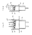
- Figs. 14 to 16 show a further embodiment of a high-voltage through-type ceramic capacitor according to the present invention.
- an insulation case 54 is enlarged at a portion thereof surrounding fastening tabs 62 to form an enlarged section 86.
- the insulation case 54 is formed into an elliptic shape in plan, and, as shown in Figs. 15 and 16, the enlarged section 86 of the insulation cover 54 is enlarged at a larger diameter portion thereof by a distance of 2d 1 and at a smaller diameter portion thereof by a distance of 2d 2 . so that a distance D between a fastening tab 62 and the insulation case 54 may be increased by 2d 1 and 2d 2 at the larger diameter and smaller diameter portions, respectively.
- the remaining part of the illustrated embodiment may be constructed in substantially the same manner as the conventional ceramic capacitor as described above.
- the insulation case 54 may be wholly made of PET or nylon 66 in an integral manner. However, it may be made of a thermosetting resin material or a thermoplastic resin material. Further, the insulation case 54 may be made of different resin materials into two separate sections.
- Figs. 17 and 18 show a modification of the embodiment shown in Figs. 14 to 16, wherein an insulation case 54 is made into two sections independent from each other. More particularly, the insulation case 54 includes an upper enlarged section 86 made of a thermosetting resin material and a lower section 88 made of a thermoplastic resin material, which are independent from each other. Then, the upper enlarged section 86 is fitted at a lower end portion thereof on an upper end portion of the lower section 88.
- the thermosetting resin material used for the enlarged section 86 includes unsaturated polyester resin, epoxy resin, melamine resin, diallyl phthalate resin and the like.
- the thermoplastic resin material for the lower section 88 includes polypropylene resin, PBT resin and the like.
- the lower section 88 which is a portion of the insulation case 54 substantially contacting with an insulating resin material 58 is formed of a thermoplastic resin material. Accordingly, the modification effectively eliminates a disadvantage encountered with an insulation case made of only a thermosetting resin material that the insulation case adheres to the insulating resin material to deteriorate dielectric strength of the capacitor. Also, in the modification, the upper enlarged section 86 is made of a thermosetting resin material, resulting in effectively preventing sagging of the section 86 due to heating to further improve dielectric strength of the capacitor.
- the modification may include positioning means for carrying out positive positioning between the upper enlarged section 86 and the lower section 88 to facilitate fitting therebetween.
- the positioning means comprises a combination of a projection 90 and a recess 92 provided on opposite side surfaces of the upper and lower section 86 and 88 contacting each other in a manner to positionally correspond to each other.
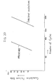
- Fig. 20 shows results of a dielectric strength test under moistening conditions which took place with respect to several samples of each of the ceramic capacitor of the embodiment shown in Figs. 14 to 16 and the conventional ceramic capacitor of Fig. 1.
- the test was carried out by subjecting each of the samples to continuous moistening by means of an ultrasonic humudifier, connecting the sample to a high-voltage transformer of an electronic oven and intermittently applying a voltage thereto by an on-off control action, to thereby measure the number of cycles at which the sample is broken down, resulting in determining relationships between the number of cycles and a cumulative failure rate of the sample.
- the ceramic capacitor of the embodiment is highly improved in humidity resistance and dielectric strength under moistening conditions as compared with the conventional through-type ceramic capacitor.
- the embodiment shown in Figs. 14 to 19 the upper portion or opening of the insulation case is likewise enlarged.
- Such construction facilitates fitting of the receptacles on the fastening tabs even when the insulation case is significantly small-sized, resulting in burning resistance and dielectric strength of the capacitor being highly improved and assembling of the capacitor being facilitated.
Claims (14)
- Verbesserter, keramischer Hochspannungskondensator vom Durchführungstyp, mit:dadurch gekennzeichnet, daß der Abschnitt des Isolationsgehäuses (54), welcher die Befestigungszungen (62) umgibt, einen vergrößerten inneren Querschnitt mit vergrößerten inneren Abmessungen aufweist im Vergleich zu den inneren Abmessungen des Abschnittes des Isolationsgehäuses (54), welcher das keramische Dielektrikum (32) umgibt.einem röhrenförmigen Isolationsgehäuse (54);einer röhrenförmigen Isolationsabdeckung (56), wobei das Isolationsgehäuse (54) und die Isolationsabdeckung (56) im wesentlichen axial ausgerichtet sind und eine Gehäuseeinheit des Kondensators bilden;einem Bodenpaßteil (40), welches zwischen dem Isolationsgehäuse (54) und der Isolationsabdeckung (56) angeordnet ist;einem keramischen Dielektrikum (32) innerhalb des Isolationsgehäuses (54), mit einem Paar von getrennten Kondensatorelektroden (36) auf einer Oberfläche desselben, und einer gemeinsamen Kondensatorelektrode (38) auf einer gegenüberliegenden Oberfläche desselben, wobei die gemeinsame Kondensatorelektrode (38) mit dem Bodenpaßteil (40) verbunden ist;einem Paar von zentralen Leitern (46), welche sich durch das Isolationsgehäuse (54) und die Isolationsabdeckung (56) erstrecken, wobei jeder der zentralen Leiter (46) mit einer der getrennten Kondensatorelektroden (36) verbunden ist, und jeder der zentralen Leiter (46) an einem Ende desselben eine Befestigungszunge (62) einschließt, angeordnet in dem Isolationsgehäuse (54);und einem isolierenden Harzmaterial (58; 60), welches in das Isolationsgehäuse (54) und die Isolationsabdeckung (56) eingefüllt ist, um so das keramische Dielektrikum (32) zu umgeben,
- Verbesserter Kondensator nach Anspruch 1,
wobei mindestens das Isolationsgehäuse (54) oder die Isolationsabdeckung (56) aus einem Material gefertigt ist, welches aus der Gruppe ausgewählt ist, die aus Polyäthylen-Terephthalat und Nylon-66 besteht. - Verbesserter Kondensator nach Anspruch 1 oder 2,
wobei das Isolationsgehäuse (54) ein inneres Gehäuseteil (54A) und ein äußeres Gehäuseteil (54B), welches auf das innere Gehäuseteil aufgesetzt ist, enthält, wobei das innere Gehäuseteil (54A) in einer Größe ausgebildet ist, die kleiner ist als die des äußeren Gehäuseteils (54B), und derart auf das äußere Gehäuseteil aufgesetzt ist, daß ein oberes Ende des inneren Gehäuseteils (55A) unterhalb eines oberen Endes des äußeren Gehäuseteils (54B) endet, was einen vergrößerten oberen Querschnitt ergibt. - Verbesserter Kondensator nach Anspruch 3,
wobei das innere Gehäuseteil (54A) aus einem thermoplastischen Harzmaterial gefertigt ist, und das äußere Gehäuseteil (54B) aus einem aushärtenden Harzmaterial gefertigt ist. - Verbesserter Kondensator nach den Ansprüchen 3 oder 4,
wobei das äußere Gehäuseteil (54B) auf einer inneren Umfangsoberfläche desselben mit einem kreisförmigen Ansatz versehen ist, wobei ein oberes Ende des inneren Gehäuseteils (54A) an den kreisförmigen Ansatz stößt. - Verbesserter, keramischer Hochspannungskondensator vom Durchführungstyp gemäß einem der Ansprüche 1 bis 5,
dadurch gekennzeichnet, daß das Isolationsgehäuse (54) aus einem einzigen Stück gefertigt ist, mit einem Hauptkörperabschnitt zusätzlich zu einem oberen Endabschnitt (86), wobei jeder vorbestimmte innere Abmessungen aufweist, wobei die inneren Abmessungen des oberen Endabschnittes (86) relativ zu den inneren Abmessungen des Hauptkörperabschnittes vergrößert sind. - Verbesserter, keramischer Hochspannungskondensator vom Durchführungstyp gemäß einem der Ansprüche 1 bis 6,
wobei das Bodenpaßteil (40) eine zentrale Schulter (44) aufweist, welche eine Öffnung (42) umgibt, sich das Isolationsgehäuse (54) über die zentrale Schulter (44) erstreckt, und sich die Isolationsabdeckung (56) innerhalb der zentralen Schulter (44) erstreckt. - Verbesserter, keramischer Hochspannungskondensator vom Durchführungstyp gemäß einem der Ansprüche 1 bis 6,
weiterhin enthaltend eine Isolationsröhre (50), welche oberhalb jedes zentralen Leiters (46) angeordnet ist, um diese von dem Isolations-Harzmaterial zu beabstanden. - Keramischer Hochspannungskondensator vom Durchführungstyp gemäß Anspruch 5,
wobei der kreisförmige Ansatz (80) seitwärts L-förmig ausgebildet ist, um so das obere Ende des inneren Gehäuseteils (54A) zu umgeben. - Keramischer Hochspannungskondensator vom Durchführungstyp gemäß Anspruch 9,
weiterhin enthaltend Positioniermittel (82, 84) zum Ausführen von Positionierung zwischen dem inneren Gehäuseteil (54A) und dem äußeren Gehäuseteil (54B). - Keramischer Hochspannungskondensator vom Durchführungstyp gemäß Anspruch 10,
wobei die Positionierungsmittel (82, 84) eine Kombination aus einem Vorsprung (82) und einer Ausnehmung (84), ausgebildet an beiden Gehäuseteilen (54A, 54B), enthält, um so miteinander in Eingriff zu stehen. - Keramischer Hochspannungskondensator vom Durchführungstyp gemäß einem der Ansprüche 1 oder 2,
dadurch gekennzeichnet, daß das Isolationsgehäuse (54) ein oberes Gehäuseteil (86) eines vergrößerten Durchmessers zum Bilden eines oberen vergrößerten Abschnittes aufweist, und ein unteres Gehäuseteil (88) eines kleineren Durchmessers aufweist, welche getrennt ausgebildet sind und miteinander verbunden sind, derart, daß ein unterer Endabschnitt des oberen Gehäuseteils (86) und ein oberer Endabschnitt des unteren Gehäuseteils (88) zusammengepaßt sind;
wobei das obere Gehäuseteil (86) aus einem aushärtenden Harzmaterial gebildet ist, und das untere Gehäuseteil (88) aus einem thermoplastischen Harzmaterial gebildet ist. - Keramischer Hochspannungskondensator vom Durchführungstyp gemäß Anspruch 12,
weiterhin enthaltend Positioniermittel (90, 92) zum Ausführen von Positionierung zwischen dem oberen Gehäuseteil (86) und dem unteren Gehäuseteil (88). - Keramischer Hochspannungskondensator vom Durchführungstyp nach Anspruch 13,
wobei die Positioniermittel (90, 92) eine Kombination aus einem Vorsprung (90) und einer Ausnehmung (92), gebildet an den oberen und unteren Endabschnitten der oberen und unteren Gehäuseteile (86, 88), enthalten, um so miteinander in Eingriff zu stehen.
Priority Applications (1)
| Application Number | Priority Date | Filing Date | Title |
|---|---|---|---|
| EP98108760A EP0878812A1 (de) | 1988-06-07 | 1989-06-03 | Keramischer Hochspannungskondensator vom Durchführungstyp |
Applications Claiming Priority (6)
| Application Number | Priority Date | Filing Date | Title |
|---|---|---|---|
| JP74739/88U | 1988-06-07 | ||
| JP1988074739U JPH01179429U (de) | 1988-06-07 | 1988-06-07 | |
| JP109046/88U | 1988-08-22 | ||
| JP1988109046U JPH0231121U (de) | 1988-08-22 | 1988-08-22 | |
| JP1988109047U JPH0231122U (de) | 1988-08-22 | 1988-08-22 | |
| JP109047/88U | 1988-08-22 |
Related Child Applications (1)
| Application Number | Title | Priority Date | Filing Date |
|---|---|---|---|
| EP98108760A Division EP0878812A1 (de) | 1988-06-07 | 1989-06-03 | Keramischer Hochspannungskondensator vom Durchführungstyp |
Publications (3)
| Publication Number | Publication Date |
|---|---|
| EP0348689A2 EP0348689A2 (de) | 1990-01-03 |
| EP0348689A3 EP0348689A3 (de) | 1990-04-25 |
| EP0348689B1 true EP0348689B1 (de) | 1998-12-09 |
Family
ID=27301605
Family Applications (2)
| Application Number | Title | Priority Date | Filing Date |
|---|---|---|---|
| EP89110073A Expired - Lifetime EP0348689B1 (de) | 1988-06-07 | 1989-06-03 | Keramischer Hochspannungskondensator vom Durchführungstyp |
| EP98108760A Withdrawn EP0878812A1 (de) | 1988-06-07 | 1989-06-03 | Keramischer Hochspannungskondensator vom Durchführungstyp |
Family Applications After (1)
| Application Number | Title | Priority Date | Filing Date |
|---|---|---|---|
| EP98108760A Withdrawn EP0878812A1 (de) | 1988-06-07 | 1989-06-03 | Keramischer Hochspannungskondensator vom Durchführungstyp |
Country Status (6)
| Country | Link |
|---|---|
| US (2) | US5032949A (de) |
| EP (2) | EP0348689B1 (de) |
| KR (1) | KR950014435B1 (de) |
| CN (1) | CN1017948B (de) |
| DE (1) | DE68928875T2 (de) |
| HK (1) | HK1014078A1 (de) |
Families Citing this family (16)
| Publication number | Priority date | Publication date | Assignee | Title |
|---|---|---|---|---|
| US5142436A (en) * | 1990-02-27 | 1992-08-25 | Samsung Electro-Mechanics Co., Ltd. | Piercing through type capacitor |
| DE69226084T2 (de) * | 1991-08-27 | 1998-12-24 | Tdk Corp | Hochspannungskondensator und magnetron |
| US5600531A (en) * | 1993-09-18 | 1997-02-04 | Daewoo Electronics Co., Ltd. | Capacitor for magnetron of microwave oven |
| US5455405A (en) * | 1993-09-18 | 1995-10-03 | Daewoo Electronics Co., Ltd. | Noise shielding apparatus for magnetron of microwave oven |
| JP3473795B2 (ja) * | 1995-05-22 | 2003-12-08 | Tdk株式会社 | 高電圧コンデンサ及びマグネトロン |
| US5650759A (en) * | 1995-11-09 | 1997-07-22 | Hittman Materials & Medical Components, Inc. | Filtered feedthrough assembly having a mounted chip capacitor for medical implantable devices and method of manufacture therefor |
| US6023408A (en) | 1996-04-09 | 2000-02-08 | The Board Of Trustees Of The University Of Arkansas | Floating plate capacitor with extremely wide band low impedance |
| JPH1092693A (ja) * | 1996-09-18 | 1998-04-10 | Tdk Corp | 貫通型セラミックコンデンサ |
| JPH10149948A (ja) * | 1996-11-19 | 1998-06-02 | Tdk Corp | 高電圧貫通形コンデンサ |
| JP3248619B2 (ja) * | 1999-03-05 | 2002-01-21 | ティーディーケイ株式会社 | 高電圧貫通型コンデンサ及びマグネトロン |
| JP3803258B2 (ja) * | 2000-04-03 | 2006-08-02 | Tdk株式会社 | 高電圧貫通型コンデンサ及びマグネトロン |
| KR100591307B1 (ko) * | 2003-12-30 | 2006-06-19 | 엘지전자 주식회사 | 마그네트론용 고전압 입력 단자 |
| US20050146833A1 (en) * | 2004-01-05 | 2005-07-07 | Brent Beamer | Methods and apparatus for a disposable grounding device |
| CN100428379C (zh) * | 2004-03-28 | 2008-10-22 | 俞斌 | 高压陶瓷穿芯电容器 |
| CN103794365A (zh) * | 2011-04-01 | 2014-05-14 | 徐孝华 | 一种高压穿通型陶瓷电容器 |
| CN102881399A (zh) * | 2012-07-16 | 2013-01-16 | 艾通电磁技术(昆山)有限公司 | 线圈接头模块及其制造方法 |
Family Cites Families (7)
| Publication number | Priority date | Publication date | Assignee | Title |
|---|---|---|---|---|
| DE965757C (de) * | 1943-08-08 | 1957-06-19 | Lorenz C Ag | Wickelkondensator mit stirnseitig aufgeschobenen Metallkappen |
| US3806770A (en) * | 1973-02-21 | 1974-04-23 | Mallory & Co Inc P R | Electrical capacitor with non-inductive leads |
| US4370698A (en) * | 1979-10-08 | 1983-01-25 | Tdk Electronics Co., Ltd. | Through type high-withstand-voltage ceramic |
| US4558399A (en) * | 1981-10-19 | 1985-12-10 | Nippon Chemi-Con Corporation | Electrolytic capacitor and a process for producing the same |
| US4768129A (en) * | 1986-01-17 | 1988-08-30 | Tdk Corporation | Through type twin capacitor |
| KR880003356A (ko) * | 1986-08-13 | 1988-05-16 | 무라다 아끼라 | 고압콘덴서 |
| EP0259766B1 (de) * | 1986-09-11 | 1992-09-16 | TDK Corporation | Durchführungstypkondensator, sowie seine Verwendung in einem Magnetron |
-
1989
- 1989-06-02 US US07/360,521 patent/US5032949A/en not_active Expired - Lifetime
- 1989-06-03 EP EP89110073A patent/EP0348689B1/de not_active Expired - Lifetime
- 1989-06-03 DE DE68928875T patent/DE68928875T2/de not_active Expired - Fee Related
- 1989-06-03 EP EP98108760A patent/EP0878812A1/de not_active Withdrawn
- 1989-06-07 CN CN89107188A patent/CN1017948B/zh not_active Expired
- 1989-06-07 KR KR1019890007826A patent/KR950014435B1/ko not_active IP Right Cessation
-
1991
- 1991-06-27 US US07/722,019 patent/US5113309A/en not_active Expired - Lifetime
-
1998
- 1998-12-23 HK HK98115154A patent/HK1014078A1/xx not_active IP Right Cessation
Also Published As
| Publication number | Publication date |
|---|---|
| EP0878812A1 (de) | 1998-11-18 |
| DE68928875T2 (de) | 1999-05-12 |
| US5113309A (en) | 1992-05-12 |
| CN1041060A (zh) | 1990-04-04 |
| DE68928875D1 (de) | 1999-01-21 |
| KR950014435B1 (ko) | 1995-11-27 |
| KR910001827A (ko) | 1991-01-31 |
| EP0348689A3 (de) | 1990-04-25 |
| CN1017948B (zh) | 1992-08-19 |
| HK1014078A1 (en) | 1999-09-17 |
| EP0348689A2 (de) | 1990-01-03 |
| US5032949A (en) | 1991-07-16 |
Similar Documents
| Publication | Publication Date | Title |
|---|---|---|
| EP0348689B1 (de) | Keramischer Hochspannungskondensator vom Durchführungstyp | |
| EP0259766B1 (de) | Durchführungstypkondensator, sowie seine Verwendung in einem Magnetron | |
| US7184256B1 (en) | High-voltage feed-through capacitor and magnetron | |
| US4768129A (en) | Through type twin capacitor | |
| EP0604652B1 (de) | Hochspannungskondensator und magnetron | |
| JPH10149948A (ja) | 高電圧貫通形コンデンサ | |
| US3541478A (en) | Electrical filter body construction having deposited outer surface | |
| EP0026842A2 (de) | Elektrolyt-Kondensator mit niedriger Induktivität | |
| US6344962B2 (en) | High voltage capacitor and magnetron | |
| US4025714A (en) | Self-locking terminal assembly | |
| EP0408289B1 (de) | Störfreie Kondensatoreinheit für Fahrzeuggenerator | |
| JPH0423310Y2 (de) | ||
| JPH0878154A (ja) | 電子レンジ用マグネトロンのノイズ遮蔽装置 | |
| JP3690662B2 (ja) | 高電圧貫通型コンデンサ及びマグネトロン | |
| US4302736A (en) | Electrical composite part | |
| JPS5930521Y2 (ja) | 高電圧貫通形コンデンサ | |
| KR960006059Y1 (ko) | 전자렌지의 마그네트론 관통형 커패시터의 구조 | |
| JPH0423312Y2 (de) | ||
| JPH0419786Y2 (de) | ||
| JPS5926543Y2 (ja) | アンテナ接栓端子 | |
| JPH029533Y2 (de) | ||
| JPH02132735A (ja) | 高圧コンデンサ型入力端子の製造方法 | |
| KR820002492Y1 (ko) | 전기 복합부품 | |
| JPH0121553Y2 (de) | ||
| KR910006685B1 (ko) | 고전압 발생기 |
Legal Events
| Date | Code | Title | Description |
|---|---|---|---|
| PUAI | Public reference made under article 153(3) epc to a published international application that has entered the european phase |
Free format text: ORIGINAL CODE: 0009012 |
|
| AK | Designated contracting states |
Kind code of ref document: A2 Designated state(s): DE FR GB NL |
|
| PUAL | Search report despatched |
Free format text: ORIGINAL CODE: 0009013 |
|
| AK | Designated contracting states |
Kind code of ref document: A3 Designated state(s): DE FR GB NL |
|
| 17P | Request for examination filed |
Effective date: 19901012 |
|
| 17Q | First examination report despatched |
Effective date: 19931011 |
|
| GRAG | Despatch of communication of intention to grant |
Free format text: ORIGINAL CODE: EPIDOS AGRA |
|
| GRAG | Despatch of communication of intention to grant |
Free format text: ORIGINAL CODE: EPIDOS AGRA |
|
| GRAH | Despatch of communication of intention to grant a patent |
Free format text: ORIGINAL CODE: EPIDOS IGRA |
|
| GRAH | Despatch of communication of intention to grant a patent |
Free format text: ORIGINAL CODE: EPIDOS IGRA |
|
| GRAA | (expected) grant |
Free format text: ORIGINAL CODE: 0009210 |
|
| AK | Designated contracting states |
Kind code of ref document: B1 Designated state(s): DE FR GB NL |
|
| PG25 | Lapsed in a contracting state [announced via postgrant information from national office to epo] |
Ref country code: NL Free format text: LAPSE BECAUSE OF FAILURE TO SUBMIT A TRANSLATION OF THE DESCRIPTION OR TO PAY THE FEE WITHIN THE PRESCRIBED TIME-LIMIT Effective date: 19981209 |
|
| REF | Corresponds to: |
Ref document number: 68928875 Country of ref document: DE Date of ref document: 19990121 |
|
| ET | Fr: translation filed | ||
| NLV1 | Nl: lapsed or annulled due to failure to fulfill the requirements of art. 29p and 29m of the patents act | ||
| PLBE | No opposition filed within time limit |
Free format text: ORIGINAL CODE: 0009261 |
|
| STAA | Information on the status of an ep patent application or granted ep patent |
Free format text: STATUS: NO OPPOSITION FILED WITHIN TIME LIMIT |
|
| 26N | No opposition filed | ||
| REG | Reference to a national code |
Ref country code: GB Ref legal event code: IF02 |
|
| REG | Reference to a national code |
Ref country code: GB Ref legal event code: 746 Effective date: 20040505 |
|
| REG | Reference to a national code |
Ref country code: FR Ref legal event code: D6 |
|
| PGFP | Annual fee paid to national office [announced via postgrant information from national office to epo] |
Ref country code: DE Payment date: 20070531 Year of fee payment: 19 |
|
| PGFP | Annual fee paid to national office [announced via postgrant information from national office to epo] |
Ref country code: GB Payment date: 20070530 Year of fee payment: 19 |
|
| PGFP | Annual fee paid to national office [announced via postgrant information from national office to epo] |
Ref country code: FR Payment date: 20070608 Year of fee payment: 19 |
|
| GBPC | Gb: european patent ceased through non-payment of renewal fee |
Effective date: 20080603 |
|
| REG | Reference to a national code |
Ref country code: FR Ref legal event code: ST Effective date: 20090228 |
|
| PG25 | Lapsed in a contracting state [announced via postgrant information from national office to epo] |
Ref country code: DE Free format text: LAPSE BECAUSE OF NON-PAYMENT OF DUE FEES Effective date: 20090101 |
|
| PG25 | Lapsed in a contracting state [announced via postgrant information from national office to epo] |
Ref country code: GB Free format text: LAPSE BECAUSE OF NON-PAYMENT OF DUE FEES Effective date: 20080603 |
|
| PG25 | Lapsed in a contracting state [announced via postgrant information from national office to epo] |
Ref country code: FR Free format text: LAPSE BECAUSE OF NON-PAYMENT OF DUE FEES Effective date: 20080630 |