EP0348367B1 - Formwerkzeug - Google Patents
Formwerkzeug Download PDFInfo
- Publication number
- EP0348367B1 EP0348367B1 EP89850154A EP89850154A EP0348367B1 EP 0348367 B1 EP0348367 B1 EP 0348367B1 EP 89850154 A EP89850154 A EP 89850154A EP 89850154 A EP89850154 A EP 89850154A EP 0348367 B1 EP0348367 B1 EP 0348367B1
- Authority
- EP
- European Patent Office
- Prior art keywords
- mould
- cavity
- moulding
- diaphragm
- space
- Prior art date
- Legal status (The legal status is an assumption and is not a legal conclusion. Google has not performed a legal analysis and makes no representation as to the accuracy of the status listed.)
- Expired
Links
- 238000000465 moulding Methods 0.000 title claims description 22
- 239000002994 raw material Substances 0.000 claims description 19
- 238000001746 injection moulding Methods 0.000 claims description 12
- 239000007787 solid Substances 0.000 claims description 7
- 230000009471 action Effects 0.000 claims description 4
- 238000000748 compression moulding Methods 0.000 claims description 3
- 230000000717 retained effect Effects 0.000 claims description 2
- 238000002347 injection Methods 0.000 description 26
- 239000007924 injection Substances 0.000 description 26
- 239000004033 plastic Substances 0.000 description 26
- 229920003023 plastic Polymers 0.000 description 26
- 239000000463 material Substances 0.000 description 23
- 239000012528 membrane Substances 0.000 description 6
- 238000000034 method Methods 0.000 description 5
- 230000006835 compression Effects 0.000 description 3
- 238000007906 compression Methods 0.000 description 3
- 239000011521 glass Substances 0.000 description 3
- 238000004519 manufacturing process Methods 0.000 description 3
- 239000002184 metal Substances 0.000 description 3
- 229910052751 metal Inorganic materials 0.000 description 3
- 230000008569 process Effects 0.000 description 3
- 229910000831 Steel Inorganic materials 0.000 description 2
- 230000008859 change Effects 0.000 description 2
- 230000001419 dependent effect Effects 0.000 description 2
- 239000010959 steel Substances 0.000 description 2
- 230000015572 biosynthetic process Effects 0.000 description 1
- 230000000295 complement effect Effects 0.000 description 1
- 239000013013 elastic material Substances 0.000 description 1
- 239000007788 liquid Substances 0.000 description 1
- 150000002739 metals Chemical class 0.000 description 1
- 239000000203 mixture Substances 0.000 description 1
- 239000002991 molded plastic Substances 0.000 description 1
- 230000000149 penetrating effect Effects 0.000 description 1
- 230000035515 penetration Effects 0.000 description 1
- 239000000843 powder Substances 0.000 description 1
- 238000003825 pressing Methods 0.000 description 1
- 230000008439 repair process Effects 0.000 description 1
- 238000007493 shaping process Methods 0.000 description 1
Images
Classifications
-
- B—PERFORMING OPERATIONS; TRANSPORTING
- B29—WORKING OF PLASTICS; WORKING OF SUBSTANCES IN A PLASTIC STATE IN GENERAL
- B29C—SHAPING OR JOINING OF PLASTICS; SHAPING OF MATERIAL IN A PLASTIC STATE, NOT OTHERWISE PROVIDED FOR; AFTER-TREATMENT OF THE SHAPED PRODUCTS, e.g. REPAIRING
- B29C45/00—Injection moulding, i.e. forcing the required volume of moulding material through a nozzle into a closed mould; Apparatus therefor
- B29C45/17—Component parts, details or accessories; Auxiliary operations
- B29C45/26—Moulds
- B29C45/37—Mould cavity walls, i.e. the inner surface forming the mould cavity, e.g. linings
-
- B—PERFORMING OPERATIONS; TRANSPORTING
- B29—WORKING OF PLASTICS; WORKING OF SUBSTANCES IN A PLASTIC STATE IN GENERAL
- B29C—SHAPING OR JOINING OF PLASTICS; SHAPING OF MATERIAL IN A PLASTIC STATE, NOT OTHERWISE PROVIDED FOR; AFTER-TREATMENT OF THE SHAPED PRODUCTS, e.g. REPAIRING
- B29C33/00—Moulds or cores; Details thereof or accessories therefor
- B29C33/0033—Moulds or cores; Details thereof or accessories therefor constructed for making articles provided with holes
-
- B—PERFORMING OPERATIONS; TRANSPORTING
- B29—WORKING OF PLASTICS; WORKING OF SUBSTANCES IN A PLASTIC STATE IN GENERAL
- B29C—SHAPING OR JOINING OF PLASTICS; SHAPING OF MATERIAL IN A PLASTIC STATE, NOT OTHERWISE PROVIDED FOR; AFTER-TREATMENT OF THE SHAPED PRODUCTS, e.g. REPAIRING
- B29C33/00—Moulds or cores; Details thereof or accessories therefor
- B29C33/30—Mounting, exchanging or centering
-
- B—PERFORMING OPERATIONS; TRANSPORTING
- B29—WORKING OF PLASTICS; WORKING OF SUBSTANCES IN A PLASTIC STATE IN GENERAL
- B29C—SHAPING OR JOINING OF PLASTICS; SHAPING OF MATERIAL IN A PLASTIC STATE, NOT OTHERWISE PROVIDED FOR; AFTER-TREATMENT OF THE SHAPED PRODUCTS, e.g. REPAIRING
- B29C43/00—Compression moulding, i.e. applying external pressure to flow the moulding material; Apparatus therefor
- B29C43/32—Component parts, details or accessories; Auxiliary operations
- B29C43/36—Moulds for making articles of definite length, i.e. discrete articles
- B29C43/38—Moulds for making articles of definite length, i.e. discrete articles with means to avoid flashes
-
- B—PERFORMING OPERATIONS; TRANSPORTING
- B29—WORKING OF PLASTICS; WORKING OF SUBSTANCES IN A PLASTIC STATE IN GENERAL
- B29C—SHAPING OR JOINING OF PLASTICS; SHAPING OF MATERIAL IN A PLASTIC STATE, NOT OTHERWISE PROVIDED FOR; AFTER-TREATMENT OF THE SHAPED PRODUCTS, e.g. REPAIRING
- B29C45/00—Injection moulding, i.e. forcing the required volume of moulding material through a nozzle into a closed mould; Apparatus therefor
- B29C45/17—Component parts, details or accessories; Auxiliary operations
- B29C45/26—Moulds
- B29C45/36—Moulds having means for locating or centering cores
-
- B—PERFORMING OPERATIONS; TRANSPORTING
- B29—WORKING OF PLASTICS; WORKING OF SUBSTANCES IN A PLASTIC STATE IN GENERAL
- B29C—SHAPING OR JOINING OF PLASTICS; SHAPING OF MATERIAL IN A PLASTIC STATE, NOT OTHERWISE PROVIDED FOR; AFTER-TREATMENT OF THE SHAPED PRODUCTS, e.g. REPAIRING
- B29C43/00—Compression moulding, i.e. applying external pressure to flow the moulding material; Apparatus therefor
-
- B—PERFORMING OPERATIONS; TRANSPORTING
- B29—WORKING OF PLASTICS; WORKING OF SUBSTANCES IN A PLASTIC STATE IN GENERAL
- B29C—SHAPING OR JOINING OF PLASTICS; SHAPING OF MATERIAL IN A PLASTIC STATE, NOT OTHERWISE PROVIDED FOR; AFTER-TREATMENT OF THE SHAPED PRODUCTS, e.g. REPAIRING
- B29C45/00—Injection moulding, i.e. forcing the required volume of moulding material through a nozzle into a closed mould; Apparatus therefor
Definitions
- the present invention relates to a moulding tool including a mould with a cavity in which raw material intended for moulding a body is introduced and moulded under pressure, at least one diaphragm defining the cavity, a space at the diaphragm on its side facing away from the cavity and a duct to this space through which a pressurised medium can be supplied to said space.
- the other end of the core engages against the opposing cavity wall, and the engagement surface there between is here called the "core print".
- core print The other end of the core engages against the opposing cavity wall, and the engagement surface there between is here called the "core print".
- the mould has an upper and a lower half defining a cavity in which the plates are formed.
- a diaphragm which is fastened at its periphery to the lower mould half.
- China material is spread over the diaphragm, which is pressed upwards by a pressurised medium let in under the diaphragm.
- the diapragm is so formed that it gives a smooth edge of the plate. Cores are not disclosed in the cavity and the problem with cores engaging against a cavity wall is not mentioned.
- the international patent application WO-A1- 86/07005 shows a mould with an upper and a lower half defining a cavity for forming polymeric products.
- the mould has an elastic membrane fastned to the lower mould half and a duct for a pressurised medium, which is let in under the membrane.
- a sheet of polymeric material is clamped between the mould halves over the membrane and is formed by the pressurised medium deforming the membrane. Cores in the cavity are not disclosed.
- SE-B- 8300391-3, UA-A- 4,330,250 and WO-A1- 86/07005 the patent US-A- 4,330,250 closest defines the prior art for the present invention.
- a mould for injection moulding a plastics frame on a glass pane is illustrated in the Swedish patent 8300391-3.
- the mould has two halves, the cavities of which form a cavity corresponding to the shape of the frame.
- the edge parts of the glass pane project into the cavity and each of the mould havles has a projecting edge part engaging against the pane.
- strips of elastic material are clamped in the gap. This method is only usable for relatively low pressures in the mould, and the method is complicated to apply.
- the object of the present invention is to solve the above mentioned problem with a gap between the cavity wall and a solid body in the mould cavity.
- Raw material intended for moulding can penetrate into this gap.
- the problem is solved in accordance with the invention by a moulding tool as specified in claim 1 where by the cavity having a wall comprising a flexible membrane.
- the membrane can be displaced into contact with the solid body by a pressurised medium and can be kept in engagement with the solid body during the moulding process.
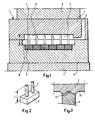
- FIG. 1 there is illustrated a mould 1 for injection moulding plastics to the known art.
- the mould in the example is intended for electrical connection means, including an elongate plastics body with two rows of holes.
- the holes are intended for metal connection pins.
- the mould has upper 2 and lower 3 mould halves which are recessed on their mutually opposing surfaces. The recesses form together a cavity corresponding to the shape of the connection means.
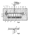
- the recess in the lower mould half 3 has core blocks, each of which has two cores 6. These cores form holes in the plastic body for the electrical connection pins.
- Both mould halves 2 and 3 are mutually located with the aid of a table 7 and an upper movable part 8 in a press, which is not more closely illustrated.
- the upper mould half 2 has a sprue 9, through which the raw plastics material is injected under pressure into the cavity 4.
- the plastics material shall therefore have a uniform structure in the entire plastic body, which can only be achieved by the raw material being injected from one end of the cavity 4 through the illustrated sprue 9.
- the pressure at which the raw material is injected is often very high, over 1500 bar, for the material to fill the cavity properly, even right up to its farther end. This high pressure is the cause of the material in the mould halves 2 and 3 being compacted.
- the cores have a length L1, which is somewhat greater than the height L2 of the cavity 4, so that during injection the cores engage against the upper wall 10 of the cavity at the core print 11, as mentioned in thee introduction.
- a detail of the core print is illustrated in Figure 3.
- the core 6 has at its free end a projection 12, which projects into a complementary recess in the upper mould half 2 for locating the core laterally. Injection of the raw material takes place at a great rate, and the material flowing in can deflect the cores 6 laterally if they do not have the projection 12.
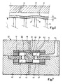
- a mould 21 for injection moulding the plastic body to the mentioned electrical connection means has an upper 22 and a lower 23 mould half. These mould halves are kept in mutual engagement by unillustrated means in a corresponding way as that illustated in Figure 1.
- the halves 22 and 23 each has a recess for a cavity 24 in the mould 21.
- the core blocks 25 are fastened in the recess in the lower half 23, and each block has two cores for shaping holes in the plastic body.
- the recess in the upper half has a diaphragm 27, which constistutes a defining wall in the cavity 24.
- the diaphragm 27 is retained in the recess in the upper half with the aid of an intermediate member 28, which is fixed to the upper half 22 with the aid of screws 29.
- the diaphragm 27 has an edge part 30, the thickness of which is greater than that of the diaphragm. Between this edge part and the bottom of the recess is gasket 30a.
- Raw material plastics in the example, can be injected under pressure through the sprue into the cavity 24 to form the plastics body.
- the raw material is injected with the aid of an injection means which is not illustrated in Figure 4.
- injection takes place under high pressure.
- the space 31 behind the diaphragm 27 is filled with a medium, e.g. oil, which is put under pressure with the aid of a pump 34 and an associated oil reservoir 34, which are schematically illustrated in the Figure.
- the pressurised oil is capable of bulging the diaphragm 27 and keeping it in engagement against the ends 36 of the cores 26 during injection.
- the material in the mould halves 22 and 23 is compacted during injection, as described above, but since the diaphragm 27 bulges out, this changing shape of the mould 21 is compensated.
- the oil pressure in the space 31 can be applied before injection starts, and this oil pressure and the pressure in the injection means can be selected mutually independently.
- the core blocks 25 have substantially the same implementation as illustrated in Figure 2.
- the ends 36 of the cores 26 may have a simple embodiment in the inventive mould, which is more closely illustated in Figure 5.
- the ends 36 are flat and engage against the flat diaphragm 27.
- the core 26 in the embodiment example illustrated in Figure 4 has a nominal length L.
- the actual length of cores deviates from the nominal length, due to limited manufacturing accuracy.
- the deviations from the nominal length L which can be permitted are relatively great for the inventive mould 21, since the diaphragm 27 can assume a curvilinear profile, as illustrated in Figure 6.
- the actual length of the core 26 is within an interval ⁇ L about the nominal length L.
- the cores can be deflected laterally under the action of forces from the material injected through the sprue 33.
- this lateral deflection is prevented by the cores 26 engagaing securely against the diaphragm 27, as described above.
- the force with which the diaphragm 27 engages against the ends 36 of the cores 26 is dependent, inter alia, on the oil pressure in the space 31, the thickness of the diaphragm 27 and the size of the length interval ⁇ L.
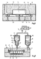
- a mould 40 has an upper 41 and lower 42 half, each with its recess for a cavity 43.
- the recess in the upper half 41 has a first diaphragm 44, constituting a first defining wall of the cavity 43.
- the recess in the lower half 42 has a second diaphragm 45 constituting a second defining wall of the cavity 43.
- the cavity 43 is provided with a metal block 50 around which plastics material shall be injected.
- the block 50 has the shape of a plate 51 provided with holes 52 and a projection 53 on either side of the plate.
- a mould 71 for injection moulding plastics has an upper 72 and a lower 73 mould half.
- the upper half has a recess constituting the mould cavity 74.
- the lower half 73 is flat and has a diaphragm 75 defining a space 76 in this half on the rear side of the diaphragm.
- the space 76 has a duct 77 through which pressurised oil can be introduced into the space 76.
- the upper half has an engagement surface 78 engaging against the lower half, and the diaphragm 75 extends under this engagement surface.
- Raw material is injected into the cavity 74 via a sprue 79, and oil in the space 76 is pressurised.
- the diaphragm 75 This causes the diaphragm 75 to deflect and engage against the edge region 80 of the engagement surface 78.
- the diaphragm thus prevents the raw material from coming in between the halves 72 and 73 and counteracts the formation of flash on the edges of the moulded product.
- FIG 9 there is schematically illustrated the inventive mould 21 according to Figure 4 connected to a hydraulic apparatus, through which raw material 68 is injected into the cavity 24, and oil is supplied to the space 31.
- the hydraulic apparatus includes the pump 34 oil reservoir 35.
- the pump is connected via a pressure line to a pressure booster 61 and an injection means 62 for the raw material.
- the pressure booster has a first chamber with a first piston 63 which is connected via a plunger 64 to a second piston 65 in a second chamber.
- the piston 63 has a larger area than the second piston 65 and the piston move in the longitudinal direction of the plunger.
- the second chamber is connected via the duct 32 to the space 31.
- the injection means 62 has a chamber for the raw material, above which there is a piston 66, which is movable in the longitudinal direction of the chamber.
- the injection means is connected via the sprue 33 to the cavity 24.
- the space between the pump 34 and pistons 63 and 66, respectively, are filled with oil 67 from the reservoir 35.
- the space 31 and the space above the piston 65 are filled with oil, and the chamber of the injection means under the piston 66 is filled with the raw material 68.
- the pump 34 supplies oil under pressure, which varies during injection, causing the pistons 63 and 66 to be displaced.
- the plastics material is thus injected under pressure into the cavity 24 and the piston 63 actuates the piston 65 for supplying pressurised oil to the space 31.
- the pressure in the space 31 is greater than the pressure which the injection means is capable of providing in the cavity 24, due to the first piston 63 of the pressure booster 61 having a greater area than its second piston 65.
- the oil in the space thus keeps the diaphragm 27 in engagement against the ends of the cores 36 during the entire injection operation, due to its greater pressure.
- the space 31 and injection means 62 may be connected to individual pumps, in which case the pressure in the space 31 can be raised to a desired value before Injection is started.
- the inventive moulding tool can be utilised for other materials, e.g. for compression moulding of metals or vulcanising rubber.
- the plastics material can be of different composition, e.g. as powder or melted.
- the medium supplied to the space 31 behind the diaphragm 27 has been a liquid (oil) in the examples, but may be a gaseous medium.
- the invention can be applied to a mould without a sprue, e.g. in a process where a product is preformed in a preforming mould of known embodiment.
- the preformed product is placed in an inventive mould with a diaphragm and subjected to a further moulding operation, e.g. curing.
- An inventive mould for this process is of the same embodiment as illustrated in Figure 7, for example, but does not have the sprue 54.
- the inventive moulding tool has several advantages compared with known tools.
- the cores 26 have a simple embodiment, as described in connection with Figure 5. In spite of the simple implementation of the cores, products having a very high quality are obtained.
- the cores are subjected to considerably less deformation than in known moulding tools, and have therefore greater life span. There is thus avoided production downtime and repair costs, which are considerable in known moulding tools.
- the manufactured products do not have flash after moulding, and further work on them is avoided.
Landscapes
- Engineering & Computer Science (AREA)
- Mechanical Engineering (AREA)
- Manufacturing & Machinery (AREA)
- Moulds For Moulding Plastics Or The Like (AREA)
- Injection Moulding Of Plastics Or The Like (AREA)
Claims (5)
Applications Claiming Priority (2)
| Application Number | Priority Date | Filing Date | Title |
|---|---|---|---|
| SE8802385 | 1988-06-23 | ||
| SE8802385A SE461456B (sv) | 1988-06-23 | 1988-06-23 | Formverktyg |
Publications (2)
| Publication Number | Publication Date |
|---|---|
| EP0348367A1 EP0348367A1 (de) | 1989-12-27 |
| EP0348367B1 true EP0348367B1 (de) | 1992-06-03 |
Family
ID=20372733
Family Applications (1)
| Application Number | Title | Priority Date | Filing Date |
|---|---|---|---|
| EP89850154A Expired EP0348367B1 (de) | 1988-06-23 | 1989-05-11 | Formwerkzeug |
Country Status (5)
| Country | Link |
|---|---|
| US (1) | US4968237A (de) |
| EP (1) | EP0348367B1 (de) |
| DE (1) | DE68901688T2 (de) |
| FI (1) | FI96749C (de) |
| SE (1) | SE461456B (de) |
Families Citing this family (7)
| Publication number | Priority date | Publication date | Assignee | Title |
|---|---|---|---|---|
| DE4317476C2 (de) * | 1993-05-26 | 1996-05-15 | Kloeckner Desma Elastomertechn | Vorrichtung zur Austriebsminimierung an Spritzgießteilen |
| SE514116C2 (sv) | 1994-10-19 | 2001-01-08 | Ericsson Telefon Ab L M | Förfarande för framställning av en kapslad optokomponent, gjutform för kapsling av en optokomponent och tryckanordning för gjutform |
| DE19801328C2 (de) * | 1998-01-16 | 2003-03-13 | Rolf Hullmann | Herstellung von aufgeschäumten Formkörpern |
| EP1220309A1 (de) * | 2000-12-28 | 2002-07-03 | STMicroelectronics S.r.l. | Herstellungsverfahren einer elektronischen Packungsanordnung |
| DE10135724B4 (de) * | 2001-07-26 | 2005-07-21 | Müller Weingarten AG | Abdichtung von Formen |
| FR2891489B1 (fr) * | 2005-10-04 | 2007-12-07 | Michelin Soc Tech | Moule pour bande de roulement de pneumatique. |
| US11577431B2 (en) * | 2020-09-23 | 2023-02-14 | Saudi Arabian Oil Company | Active self-shaping non-Newtonian fluid based system and method for rapid mold tooling |
Family Cites Families (5)
| Publication number | Priority date | Publication date | Assignee | Title |
|---|---|---|---|---|
| US2575734A (en) * | 1947-12-30 | 1951-11-20 | Westinghouse Electric Corp | Press |
| US2658237A (en) * | 1948-12-14 | 1953-11-10 | Hydraulic Molds Corp | Injection molding apparatus |
| DE2933226C2 (de) * | 1979-08-16 | 1983-11-10 | Dorst-Keramikmaschinen-Bau Otto Dorst U. Dipl.-Ing. Walter Schlegel, 8113 Kochel | Membran für eine Presse zum Herstellen von Tellern o.dgl. |
| SE446611B (sv) * | 1985-02-06 | 1986-09-29 | Asea Ab | Press av tryckcelltyp |
| BR8502414A (pt) * | 1985-05-21 | 1986-12-30 | Luiz Carlos Oliveira Da Cunha | Processo para moldar produtos polimericos com reforco de fibras ou filamentos |
-
1988
- 1988-06-23 SE SE8802385A patent/SE461456B/sv not_active IP Right Cessation
-
1989
- 1989-05-11 DE DE8989850154T patent/DE68901688T2/de not_active Expired - Lifetime
- 1989-05-11 EP EP89850154A patent/EP0348367B1/de not_active Expired
- 1989-05-18 FI FI892402A patent/FI96749C/sv not_active IP Right Cessation
- 1989-06-12 US US07/364,239 patent/US4968237A/en not_active Expired - Lifetime
Also Published As
| Publication number | Publication date |
|---|---|
| SE8802385D0 (sv) | 1988-06-23 |
| US4968237A (en) | 1990-11-06 |
| FI892402A0 (fi) | 1989-05-18 |
| FI892402A7 (fi) | 1989-12-24 |
| SE8802385L (sv) | 1989-12-24 |
| SE461456B (sv) | 1990-02-19 |
| FI96749B (sv) | 1996-05-15 |
| DE68901688D1 (de) | 1992-07-09 |
| DE68901688T2 (de) | 1992-12-17 |
| FI96749C (sv) | 1996-08-26 |
| EP0348367A1 (de) | 1989-12-27 |
Similar Documents
| Publication | Publication Date | Title |
|---|---|---|
| US6413074B1 (en) | Assembly for molding plastic material | |
| EP0348367B1 (de) | Formwerkzeug | |
| CA2098854A1 (en) | Manufacturing device and manufacturing method for multi-layer molded-product | |
| WO1991017035A1 (en) | Method and apparatus for producing structural injection moldings | |
| EP0633115A1 (de) | Spritzprägeverfahren zum Herstellen von Komplex geformten Produkten aus elastomerem Material | |
| CN210651692U (zh) | 真空注塑模具 | |
| EP0787567A3 (de) | Verfahren zur Herstellung optischer Halbzeugen und optischer Gegenstände durch Pressformen | |
| US20040145090A1 (en) | Method and mold assembly for producing a molded object | |
| CN218314960U (zh) | 汽车电控盒模具 | |
| CN113977840A (zh) | 一种硅胶制品挤压机的镶拼式模具结构 | |
| JPH0536645Y2 (de) | ||
| CN213617890U (zh) | 一种聚氨酯弹性体制品浇注模具 | |
| JPH039815A (ja) | 樹脂成形型 | |
| CN218838483U (zh) | 一种弯梁成型模具 | |
| CN216506422U (zh) | 一种防脱注射模 | |
| CN111136262A (zh) | 一种用于磁性材料的成型模具及其压制方法 | |
| CN215241555U (zh) | 一种自动塑形的冷等静压成型模具 | |
| CN213944546U (zh) | 一种电机壳的生产模具 | |
| CN214161124U (zh) | 一种用于生产环保设备的外模具 | |
| CN213816714U (zh) | 一种便携式插片式接触对簧片模具 | |
| CN219153516U (zh) | 一种带弯角的模具 | |
| JP3731811B2 (ja) | 合成樹脂成形品の製造方法 | |
| JPH0324345Y2 (de) | ||
| CN120921627B (zh) | 二射刻印设备及二射刻印方法 | |
| CN210679843U (zh) | 一种双曲率瓣片压制成型模具 |
Legal Events
| Date | Code | Title | Description |
|---|---|---|---|
| PUAI | Public reference made under article 153(3) epc to a published international application that has entered the european phase |
Free format text: ORIGINAL CODE: 0009012 |
|
| AK | Designated contracting states |
Kind code of ref document: A1 Designated state(s): DE FR GB NL |
|
| 17P | Request for examination filed |
Effective date: 19900529 |
|
| 17Q | First examination report despatched |
Effective date: 19910626 |
|
| GRAA | (expected) grant |
Free format text: ORIGINAL CODE: 0009210 |
|
| AK | Designated contracting states |
Kind code of ref document: B1 Designated state(s): DE FR GB NL |
|
| REF | Corresponds to: |
Ref document number: 68901688 Country of ref document: DE Date of ref document: 19920709 |
|
| ET | Fr: translation filed | ||
| PLBE | No opposition filed within time limit |
Free format text: ORIGINAL CODE: 0009261 |
|
| STAA | Information on the status of an ep patent application or granted ep patent |
Free format text: STATUS: NO OPPOSITION FILED WITHIN TIME LIMIT |
|
| 26N | No opposition filed | ||
| PGFP | Annual fee paid to national office [announced via postgrant information from national office to epo] |
Ref country code: GB Payment date: 19990421 Year of fee payment: 11 Ref country code: FR Payment date: 19990421 Year of fee payment: 11 |
|
| PGFP | Annual fee paid to national office [announced via postgrant information from national office to epo] |
Ref country code: DE Payment date: 19990422 Year of fee payment: 11 |
|
| PGFP | Annual fee paid to national office [announced via postgrant information from national office to epo] |
Ref country code: NL Payment date: 19990427 Year of fee payment: 11 |
|
| PG25 | Lapsed in a contracting state [announced via postgrant information from national office to epo] |
Ref country code: GB Free format text: LAPSE BECAUSE OF NON-PAYMENT OF DUE FEES Effective date: 20000511 |
|
| PG25 | Lapsed in a contracting state [announced via postgrant information from national office to epo] |
Ref country code: NL Free format text: LAPSE BECAUSE OF NON-PAYMENT OF DUE FEES Effective date: 20001201 |
|
| GBPC | Gb: european patent ceased through non-payment of renewal fee |
Effective date: 20000511 |
|
| PG25 | Lapsed in a contracting state [announced via postgrant information from national office to epo] |
Ref country code: FR Free format text: LAPSE BECAUSE OF NON-PAYMENT OF DUE FEES Effective date: 20010131 |
|
| NLV4 | Nl: lapsed or anulled due to non-payment of the annual fee |
Effective date: 20001201 |
|
| PG25 | Lapsed in a contracting state [announced via postgrant information from national office to epo] |
Ref country code: DE Free format text: LAPSE BECAUSE OF NON-PAYMENT OF DUE FEES Effective date: 20010301 |
|
| REG | Reference to a national code |
Ref country code: FR Ref legal event code: ST |