EP0347722B1 - Génératrice tachymétrique - Google Patents
Génératrice tachymétrique Download PDFInfo
- Publication number
- EP0347722B1 EP0347722B1 EP89110686A EP89110686A EP0347722B1 EP 0347722 B1 EP0347722 B1 EP 0347722B1 EP 89110686 A EP89110686 A EP 89110686A EP 89110686 A EP89110686 A EP 89110686A EP 0347722 B1 EP0347722 B1 EP 0347722B1
- Authority
- EP
- European Patent Office
- Prior art keywords
- coil
- windings
- pairs
- aligned
- tacho
- Prior art date
- Legal status (The legal status is an assumption and is not a legal conclusion. Google has not performed a legal analysis and makes no representation as to the accuracy of the status listed.)
- Expired - Lifetime
Links
Images


Classifications
-
- H—ELECTRICITY
- H02—GENERATION; CONVERSION OR DISTRIBUTION OF ELECTRIC POWER
- H02K—DYNAMO-ELECTRIC MACHINES
- H02K21/00—Synchronous motors having permanent magnets; Synchronous generators having permanent magnets
- H02K21/48—Generators with two or more outputs
-
- G—PHYSICS
- G01—MEASURING; TESTING
- G01P—MEASURING LINEAR OR ANGULAR SPEED, ACCELERATION, DECELERATION, OR SHOCK; INDICATING PRESENCE, ABSENCE, OR DIRECTION, OF MOVEMENT
- G01P3/00—Measuring linear or angular speed; Measuring differences of linear or angular speeds
- G01P3/42—Devices characterised by the use of electric or magnetic means
- G01P3/44—Devices characterised by the use of electric or magnetic means for measuring angular speed
- G01P3/48—Devices characterised by the use of electric or magnetic means for measuring angular speed by measuring frequency of generated current or voltage
-
- H—ELECTRICITY
- H02—GENERATION; CONVERSION OR DISTRIBUTION OF ELECTRIC POWER
- H02K—DYNAMO-ELECTRIC MACHINES
- H02K21/00—Synchronous motors having permanent magnets; Synchronous generators having permanent magnets
- H02K21/12—Synchronous motors having permanent magnets; Synchronous generators having permanent magnets with stationary armatures and rotating magnets
- H02K21/24—Synchronous motors having permanent magnets; Synchronous generators having permanent magnets with stationary armatures and rotating magnets with magnets axially facing the armatures, e.g. hub-type cycle dynamos
-
- H—ELECTRICITY
- H02—GENERATION; CONVERSION OR DISTRIBUTION OF ELECTRIC POWER
- H02K—DYNAMO-ELECTRIC MACHINES
- H02K29/00—Motors or generators having non-mechanical commutating devices, e.g. discharge tubes or semiconductor devices
- H02K29/14—Motors or generators having non-mechanical commutating devices, e.g. discharge tubes or semiconductor devices with speed sensing devices
-
- H—ELECTRICITY
- H02—GENERATION; CONVERSION OR DISTRIBUTION OF ELECTRIC POWER
- H02K—DYNAMO-ELECTRIC MACHINES
- H02K3/00—Details of windings
- H02K3/04—Windings characterised by the conductor shape, form or construction, e.g. with bar conductors
- H02K3/26—Windings characterised by the conductor shape, form or construction, e.g. with bar conductors consisting of printed conductors
-
- Y—GENERAL TAGGING OF NEW TECHNOLOGICAL DEVELOPMENTS; GENERAL TAGGING OF CROSS-SECTIONAL TECHNOLOGIES SPANNING OVER SEVERAL SECTIONS OF THE IPC; TECHNICAL SUBJECTS COVERED BY FORMER USPC CROSS-REFERENCE ART COLLECTIONS [XRACs] AND DIGESTS
- Y10—TECHNICAL SUBJECTS COVERED BY FORMER USPC
- Y10S—TECHNICAL SUBJECTS COVERED BY FORMER USPC CROSS-REFERENCE ART COLLECTIONS [XRACs] AND DIGESTS
- Y10S310/00—Electrical generator or motor structure
- Y10S310/06—Printed-circuit motors and components
Definitions
- servo-controlled motors For driving a head drum e.g. in video recorders, servo-controlled motors are known which are equipped with one or more tachogenerators according to the preamble of claim 1.
- the meandering turns and the associated pole pairs in the rotor are aligned radially.
- a signal with a frequency dependent on the rotational speed is generated in the coil formed by the meandering arrangement of the individual turns.
- This signal is evaluated in the servo system of the device in order to derive a readjustment for the speed control of the motor.
- known systems have a so-called pick-up pulse generator, by means of which one or more switching pulses are generated with each rotor revolution. These pulses are used for synchronous control between the recorded signal and the sequence control in the device.
- EP-A-0 149 360 and US-A-4 410 853 describe such tachometer generators.
- the arrangement of the pole pairs in the rotating part ie their number and direction, must correspond to the arrangement of the coils. This is achieved during a magnetization process of the magnetic disk by a single pole pair, which can be positioned accordingly using a rotary adjuster.
- the magnetization for the speed control that is to say for the frequency generator, is first carried out by magnetizing magnet pairs with +45 o over the entire circumference.
- the existing magnetization is overwritten at specific intervals which correspond to the arrangement of the mantans of the second coil.
- Fig. 1 shows an arrangement of the meandering turns in one plane for two coils with azimuth offset.
- the coils 2 and 3 are circular z. B. executed as printed conductor tracks.
- the spools are interleaved and have a common connection point A.
- the coil 2 serves as a frequency generator.
- Their meandering turns are made at an angle +, relative to a point on the center line 4.
- the individual turns are connected in series.
- Point S2 forms the connection for this coil.
- the coil 3 is provided for the generation of pick-up signals.
- the individual meandering turns are made at an angle of -.
- the connection point for this coil is S3.
- two nested coils are shown. However, it is also possible to arrange further coils on the circumference, for example for the generation of further pick-up signals.
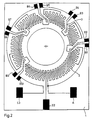
- Fig. 2 shows an arrangement corresponding to Fig.1.
- a higher frequency generator amplitude is achieved by a modified coil 2.
- Several individual pulses can be tapped at the connections B1 to B10 of coil 3.
- a printed circuit board with double-sided lamination the thickness of which should be as small as possible, it is possible to carry out the coil 2 continuously on one side of the plate, i.e. without interruption through coil 3, while on the other side the plate is the coil 3.
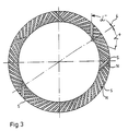
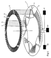
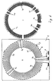
- FIG. 3 shows an arrangement of the magnetization of the magnetic disk in association with FIG. 1.
- the magnetic disk 5 is designed as a circular ring. It is coupled to the rotating part of the motor by a connection, not shown. As shown in FIG. 4, the magnetic disk 5 is arranged centrically at a short distance from the fixed printed circuit board in order to generate the largest possible signal level in the coils when the disk rotates.
- the geometrical arrangement of the pole pairs N, S shown corresponds to the arrangement of the turns of FIG. 1. The majority of the Pole pairs are arranged at an angle of +, while 5 pole pairs are at an angle of -. If the rotor turns, the 5 magnetic pole pairs and the associated meandering turns of coil 3 are directly opposite each other once per revolution.
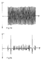
- FIG. 5a shows the voltage U of the signals of the frequency generator, ie of coil 2, over time t, while the pickup signals generated in coil 3 are shown in FIG. 5b.
- Another way of generating both frequency generator signals and pick-up signals using nested coils with the same coil diameter and the same orientation of the individual meandering turns of the coils is to use different turns for the pick-up coil and its associated magnetic pole pairs Classification within the frequency generator coil together with associated magnetic pole pairs.
- the pitch for the pick-up coil is chosen such that with an even number of turns, half of the turns have the pitch of the frequency generator, while the second half has an arrangement offset by half a pitch. It is thereby achieved that at a certain position of the magnetic disk in relation to the pick-up coil, the associated magnetic pole pairs induce in-phase voltages in the individual turns, which generate a pulse per revolution by addition.
- the magnetic pole pairs of the frequency generator in the turns of the pick-up coil generate an equal number of in-phase and out-of-phase voltages, which cancel each other out in their addition. It is also possible, by designing the arrangement of the magnetic pole pairs, to generate two or more pulses in the pick-up coil during one revolution.
- FIG. 6 shows on the left an arrangement of the meandering turns in one plane for two coils with the same coil diameter without azimuth offset.
- the coils 6 and 7 are circular, for example as a printed conductor.
- the coils are interleaved and have a common connection point A.
- the coil 6 serves as a frequency generator.
- Their meandering turns are connected in series and have cutouts in which the coil 7 is arranged.
- Point S2 forms the connection for coil 6.
- the coil 7 is provided for the generation of pick-up signals.
- the connection point for this coil is S3. While coil 6 for the frequency generator has many turns with a constant pitch, the pitch for the six turns of coil 7 is different.
- the individual turns are labeled clockwise with 7a to 7f.
- the turns of this coil are laid so that the division of the turns 7a, 7c and 7e with the division of the turns for the frequency generator match, while the windings 7b, 7d and 7f are offset by half a pitch.
- This arrangement means that the magnetic pole pairs of the frequency generator induce winding voltages in the individual turns of the pick-up coil which cancel each other out in their addition. So no voltage is generated by the magnetic pole pairs of the frequency generator in the coil 7.
- the magnetic pole pairs assigned to the windings of the pick-up coil for the pick-up generator as shown on the right in FIG.
- FIG. 7 shows a detail of the assignment of the magnetic pole pairs to the turns of the coils 6 and 7.
- the drawn position of the magnetic disk therefore corresponds to the state in which all six pick-up magnetic pole pairs are above the associated meandering turns of coil 7.
- the individual winding voltages are therefore in phase and add up to a pick-up pulse.
Claims (12)
- Génératrice tachymétrique pour un moteur à servocommande avec un arrangement de bobines (2, 3) plat, fixe, présentant des spires en forme de méandres, placé en anneau de cercle, et avec un disque magnétique (5), qui présente des paires de pôles magnétiques, qui tourne en étant centré à un faible écart au-dessus de l'arrangement de bobines, caractérisée en ce que :a) la plus grande partie des spires forment une première bobine (2), qui présente un diamètre de bobine moyen, dont les spires en forme de méandres sont orientées par rapport au diamètre du cercle (4) en formant un premier angle avec un pas uniforme et qu'un premier nombre de paires de pôles (N, S) du disque magnétique (5), qui correspond au pas et au nombre des méandres, est orienté en direction de ces méandres ;b) qu'une spire ou plusieurs spires réparties sur la périphérie du cercle, avec le diamètre moyen de la première bobine (2), forment une seconde bobine (3) dont les spires en forme de meándres sont orientées par rapport au diamètre du cercle (4) en formant un second angle et qu'un second nombre de paires de pôles du disque magnétique (5), qui correspond au nombre et au pas des spires de la seconde bobine (3), est orienté en direction de ces méandres, la répartition des secondes paires de pôles sur la périphérie étant telle qu'à une position prédéfinie du disque magnétique (5) des tensions sont induites pendant une rotation dans les différentes spires de la seconde bobine (3) par les secondes paires de pôles.
- Génératrice tachymétrique pour un moteur à servocommande avec un arrangement de bobines (6, 7) plat, fixe, présentant des spires en forme de méandres, placé en anneau de cercle, et avec un disque magnétique (8), qui présente des paires de pôles magnétiques, qui tourne en étant centré à un faible écart au-dessus de l'arrangement de bobines, caractérisée en ce que :a) la plus grande partie des spires forment une première bobine (6), qui présente un diamètre de bobine moyen, dont les spires en forme de méandres sont orientées par rapport au diamètre du cercle (4) en formant un premier angle avec un pas uniforme et qu'un premier nombre de paires de pôles (N, S) du disque magnétique (8), qui correspond au pas et au nombre des méandres, est orienté en direction de ces méandres ;b) que plusieurs spires réparties sur la périphérie d'un cercle selon un schéma prédéfini, avec le diamètre de bobine moyen de la première bobine (6) forment une seconde bobine (7) dont les spires en méandres sont orientées par rapport au diamètre du cercle (4) en formant l'angle de la première bobine (6) et qu'un second nombre de paires de pôles du disque magnétique (8), qui correspond au nombre des spires de la seconde bobine (7), est orienté en direction de ces méandres, la répartition des spires de la seconde bobine (7) et des paires de pôles correspondantes étant conçue de telle manière qu'à une position prédéfinie du disque magnétique (8) des tensions sont induites dans le même sens (de même phase) pendant une rotation dans les différentes spires de la seconde bobine (7) par les secondes paires de pôles.
- Génératrice tachymétrique selon la revendication 1, caractérisée en ce que les méandres de la première bobine (2) sont orientés par rapport au diamètre du cercle (4) en formant un angle positif et que les méandres de la seconde bobine (3) sont orientés par rapport au diamètre du cercle (4) en formant un angle négatif.
- Génératrice tachymétrique selon la revendication 3, caractérisée en ce que les deux angles sont de même grandeur.
- Génératrice tachymétrique selon la revendication 4, caractérisée en ce que les angles sont de 45°.
- Génératrice tachymétrique selon l'une des revendications 1 ou 3, caractérisée en ce que les bobines (2, 3, 6, 7) sont placées sur un côté de carte imprimée (1) en étant imbriquées l'une dans l'autre.
- Génératrice tachymétrique selon l'une des revendications 1 ou 2, caractérisée en ce que les bobines (2, 3, 6, 7) sont placées sur une carte imprimée contrecollée des deux côtés en étant séparées l'une de l'autre.
- Génératrice tachymétrique selon l'une des revendications 1 ou 2, caractérisée en ce que les paires de pôles magnétiques du disque magnétique (5, 8) sont imbriquées l'une dans l'autre.
- Génératrice tachymétrique selon l'une des revendications 1 ou 2, caractérisée en ce que le second nombre des paires de pôles (N, S) correspond au nombre des méandres qui correspondent.
- Génératrice tachymétrique selon l'une des revendications 1 ou 2, caractérisée en ce que plus de deux bobines sont imbriquées l'une dans l'autre.
- Génératrice tachymétrique selon l'une des revendications 1 ou 2, caractérisée en ce que la disposition de la deuxième bobine (3, 7) au des paires de pôles magnétiques correspondantes est choisie de telle manière qu'une ou plusieurs impulsions sont produites par rotation.
- Génératrice tachymétrique selon la revendication 2, caractérisée en ce que le nombre des enroulements de la seconde bobine (7) est pair.
Priority Applications (1)
| Application Number | Priority Date | Filing Date | Title |
|---|---|---|---|
| AT89110686T ATE83591T1 (de) | 1988-06-22 | 1989-06-13 | Tachogenerator. |
Applications Claiming Priority (2)
| Application Number | Priority Date | Filing Date | Title |
|---|---|---|---|
| DE3821050A DE3821050A1 (de) | 1988-06-22 | 1988-06-22 | Tachogenerator |
| DE3821050 | 1988-06-22 |
Publications (2)
| Publication Number | Publication Date |
|---|---|
| EP0347722A1 EP0347722A1 (fr) | 1989-12-27 |
| EP0347722B1 true EP0347722B1 (fr) | 1992-12-16 |
Family
ID=6357005
Family Applications (2)
| Application Number | Title | Priority Date | Filing Date |
|---|---|---|---|
| EP89110686A Expired - Lifetime EP0347722B1 (fr) | 1988-06-22 | 1989-06-13 | Génératrice tachymétrique |
| EP89906774A Pending EP0420885A1 (fr) | 1988-06-22 | 1989-06-13 | Generatrice tachymetrique |
Family Applications After (1)
| Application Number | Title | Priority Date | Filing Date |
|---|---|---|---|
| EP89906774A Pending EP0420885A1 (fr) | 1988-06-22 | 1989-06-13 | Generatrice tachymetrique |
Country Status (9)
| Country | Link |
|---|---|
| US (1) | US5177389A (fr) |
| EP (2) | EP0347722B1 (fr) |
| JP (1) | JP2920834B2 (fr) |
| KR (1) | KR0140523B1 (fr) |
| AT (1) | ATE83591T1 (fr) |
| DE (2) | DE3821050A1 (fr) |
| ES (1) | ES2037334T3 (fr) |
| HK (1) | HK117794A (fr) |
| WO (1) | WO1989012925A1 (fr) |
Families Citing this family (29)
| Publication number | Priority date | Publication date | Assignee | Title |
|---|---|---|---|---|
| DE3821050A1 (de) * | 1988-06-22 | 1989-12-28 | Thomson Brandt Gmbh | Tachogenerator |
| US5406155A (en) * | 1992-06-03 | 1995-04-11 | Trw Inc. | Method and apparatus for sensing relative position between two relatively rotatable members |
| US20030062889A1 (en) | 1996-12-12 | 2003-04-03 | Synaptics (Uk) Limited | Position detector |
| US6430001B1 (en) | 1995-03-16 | 2002-08-06 | International Business Machines Corporation | Integrated data storage disk and disk drive |
| US6208485B1 (en) | 1995-03-16 | 2001-03-27 | International Business Machines Corporation | Microfile |
| US5789841A (en) * | 1995-06-07 | 1998-08-04 | Kollmorgen Corporation | Axial air gap brushless motor with layered disk stator |
| US5717268A (en) * | 1996-06-17 | 1998-02-10 | Philips Electronics North America Corp. | Electric motor with tachometer signal generator |
| US6788221B1 (en) | 1996-06-28 | 2004-09-07 | Synaptics (Uk) Limited | Signal processing apparatus and method |
| EP0985132B1 (fr) | 1997-05-28 | 2005-11-09 | Synaptics (UK) Limited | Procede et dispositif de connexion de fils pour la fabrication d'un transducteur |
| GB9720954D0 (en) * | 1997-10-02 | 1997-12-03 | Scient Generics Ltd | Commutators for motors |
| GB9721891D0 (en) | 1997-10-15 | 1997-12-17 | Scient Generics Ltd | Symmetrically connected spiral transducer |
| GB9811151D0 (en) | 1998-05-22 | 1998-07-22 | Scient Generics Ltd | Rotary encoder |
| JP2002531902A (ja) | 1998-11-27 | 2002-09-24 | シナプティックス (ユーケー)リミテッド | 位置センサ |
| US7019672B2 (en) | 1998-12-24 | 2006-03-28 | Synaptics (Uk) Limited | Position sensor |
| DE60227174D1 (de) * | 2001-05-21 | 2008-07-31 | Synaptics Uk Ltd | Positionssensor |
| KR200268109Y1 (ko) * | 2001-12-06 | 2002-03-15 | 김정훈 | 편평형 무정류자 진동모터 |
| GB2403017A (en) * | 2002-03-05 | 2004-12-22 | Synaptics | Position sensor |
| WO2003105072A2 (fr) * | 2002-06-05 | 2003-12-18 | Synaptics (Uk) Limited | Procede et appareil de transfert de signal |
| GB0317370D0 (en) * | 2003-07-24 | 2003-08-27 | Synaptics Uk Ltd | Magnetic calibration array |
| GB0319945D0 (en) * | 2003-08-26 | 2003-09-24 | Synaptics Uk Ltd | Inductive sensing system |
| GB2461448B (en) | 2007-05-10 | 2011-08-31 | Cambridge Integrated Circuits Ltd | Transducer |
| JP5534338B2 (ja) | 2010-09-30 | 2014-06-25 | 日立工機株式会社 | ディスクモータ及び電動作業機 |
| JP5534337B2 (ja) * | 2010-09-30 | 2014-06-25 | 日立工機株式会社 | ディスクモータ及び電動作業機 |
| GB2488389C (en) | 2010-12-24 | 2018-08-22 | Cambridge Integrated Circuits Ltd | Position sensing transducer |
| GB2503006B (en) | 2012-06-13 | 2017-08-09 | Cambridge Integrated Circuits Ltd | Position sensing transducer |
| GB201322478D0 (en) * | 2013-12-18 | 2014-02-05 | Gyo Gym Ltd | Improvements in or relating to generating your own power |
| US11289947B2 (en) * | 2017-08-29 | 2022-03-29 | Exh Corporation | Electric power transmission system, and manufacturing method for electric power transmission system |
| US11677303B2 (en) * | 2021-10-21 | 2023-06-13 | National Cheng Kung University | Motor and coreless stator coil winding unit thereof |
| CN114814272B (zh) * | 2022-06-28 | 2022-12-16 | 四川新川航空仪器有限责任公司 | 一种磁转速传感器 |
Family Cites Families (11)
| Publication number | Priority date | Publication date | Assignee | Title |
|---|---|---|---|---|
| US2970238A (en) * | 1959-02-12 | 1961-01-31 | Printed Motors Inc | Printed circuit armature |
| DE2631017A1 (de) * | 1976-07-09 | 1978-01-12 | Oskar Hubert Richt | Tachogenerator |
| US4410853A (en) * | 1980-12-13 | 1983-10-18 | Hitachi, Ltd. | Frequency detector |
| US4488076A (en) * | 1982-09-30 | 1984-12-11 | Applied Motion Products, Inc. | Tachometer assembly for magnetic motors |
| JPS60140158A (ja) * | 1983-12-28 | 1985-07-25 | Sony Corp | 回転検出装置 |
| US4656377A (en) * | 1984-01-30 | 1987-04-07 | Victor Company Of Japan, Ltd. | Tachogenerator having a magnetoresistance stator coil |
| JPS60241756A (ja) * | 1984-05-16 | 1985-11-30 | Japan Servo Co Ltd | 周波数発電機付電動機 |
| JPS62262645A (ja) * | 1986-05-09 | 1987-11-14 | Sanyo Electric Co Ltd | ブラシレスモ−タ |
| US4751415A (en) * | 1987-04-28 | 1988-06-14 | Matsushita Electric Industrial Co., Ltd. | Brushless DC motor with means for compensating ripple torque |
| DE3821050A1 (de) * | 1988-06-22 | 1989-12-28 | Thomson Brandt Gmbh | Tachogenerator |
| US5045740A (en) * | 1988-09-16 | 1991-09-03 | Yamamoto Electric Corporation | Brushless motor |
-
1988
- 1988-06-22 DE DE3821050A patent/DE3821050A1/de not_active Withdrawn
-
1989
- 1989-06-13 KR KR1019900700376A patent/KR0140523B1/ko not_active IP Right Cessation
- 1989-06-13 DE DE8989110686T patent/DE58903000D1/de not_active Expired - Fee Related
- 1989-06-13 AT AT89110686T patent/ATE83591T1/de not_active IP Right Cessation
- 1989-06-13 WO PCT/EP1989/000663 patent/WO1989012925A1/fr not_active Application Discontinuation
- 1989-06-13 EP EP89110686A patent/EP0347722B1/fr not_active Expired - Lifetime
- 1989-06-13 JP JP1506536A patent/JP2920834B2/ja not_active Expired - Fee Related
- 1989-06-13 ES ES198989110686T patent/ES2037334T3/es not_active Expired - Lifetime
- 1989-06-13 EP EP89906774A patent/EP0420885A1/fr active Pending
-
1990
- 1990-12-18 US US07/628,911 patent/US5177389A/en not_active Expired - Lifetime
-
1994
- 1994-10-27 HK HK117794A patent/HK117794A/xx not_active IP Right Cessation
Also Published As
| Publication number | Publication date |
|---|---|
| DE58903000D1 (de) | 1993-01-28 |
| ATE83591T1 (de) | 1993-01-15 |
| US5177389A (en) | 1993-01-05 |
| JP2920834B2 (ja) | 1999-07-19 |
| KR900702625A (ko) | 1990-12-07 |
| HK117794A (en) | 1994-11-04 |
| WO1989012925A1 (fr) | 1989-12-28 |
| EP0420885A1 (fr) | 1991-04-10 |
| JPH03505395A (ja) | 1991-11-21 |
| EP0347722A1 (fr) | 1989-12-27 |
| DE3821050A1 (de) | 1989-12-28 |
| ES2037334T3 (es) | 1993-06-16 |
| KR0140523B1 (ko) | 1998-08-17 |
Similar Documents
| Publication | Publication Date | Title |
|---|---|---|
| EP0347722B1 (fr) | Génératrice tachymétrique | |
| DE3806752C2 (fr) | ||
| DE2840562C2 (de) | Elektromotor | |
| DE3140034C2 (de) | Kollektorlose Gleichstrommaschine | |
| DE2811282A1 (de) | Traegheitsrad | |
| DE2647687A1 (de) | Elektromotor mit frequenzgenerator | |
| EP0554900B1 (fr) | Moteur électrique avec un capteur inductif de position | |
| DE3590835C2 (fr) | ||
| DE3590633C2 (fr) | ||
| DE4027782A1 (de) | Elektrizitaetsgenerator | |
| DE2647675B2 (de) | Elektromotor | |
| DE2807834A1 (de) | Halleffekt-kodiergeraet fuer winkelstellungen von wellen | |
| DE2338307B2 (de) | Elektromagnetische Einrichtung zum Antrieb und zur zentrierenden Lagerung von Drehkörpern | |
| DE3044062A1 (de) | Gleichstrommotor | |
| DE2903859A1 (de) | Drehsteuerkreis | |
| DE3902485C2 (de) | Aufzeichnungsgerät | |
| DE19806611A1 (de) | Elektromechanische Bedieneinrichtung | |
| DE69727464T2 (de) | Elektromechanische vorrichtung, spulenanordnung fur diese vorrichtung und gerät fur datenspeicherung und/oder wiedergabe mit einer derartigen vorrichtung | |
| DE4218674C2 (de) | Indeximpuls-Erzeugungssystem bei einer Plattenspeicher-Vorrichtung | |
| DE69725673T2 (de) | Synchronisationsverfahren- und Vorrichtung für den Anlauf einer dreiphasigen Synchronmaschine | |
| DE3151257C2 (fr) | ||
| DE1638244A1 (de) | Reversibler,elektromechanischer Umformer | |
| DE3718207A1 (de) | Verfahren zur steuerung der drehzahl eines rotors | |
| DE3118991A1 (de) | "einrichtung zur frequenzmessung eines eine variable groesse darstellenden elektrischen stroms" | |
| DE1563418A1 (de) | Kollektorloser Gleichstrommotor |
Legal Events
| Date | Code | Title | Description |
|---|---|---|---|
| PUAI | Public reference made under article 153(3) epc to a published international application that has entered the european phase |
Free format text: ORIGINAL CODE: 0009012 |
|
| AK | Designated contracting states |
Kind code of ref document: A1 Designated state(s): ES GR |
|
| 17P | Request for examination filed |
Effective date: 19900522 |
|
| RBV | Designated contracting states (corrected) |
Designated state(s): AT BE CH DE ES FR GB GR IT LI LU NL SE |
|
| XX | Miscellaneous (additional remarks) |
Free format text: VERBUNDEN MIT 89906774.8/0420885 (EUROPAEISCHE ANMELDENUMMER/VEROEFFENTLICHUNGSNUMMER) DURCH ENTSCHEIDUNG VOM 04.03.92. |
|
| 17Q | First examination report despatched |
Effective date: 19920511 |
|
| GRAA | (expected) grant |
Free format text: ORIGINAL CODE: 0009210 |
|
| AK | Designated contracting states |
Kind code of ref document: B1 Designated state(s): AT BE CH DE ES FR GB GR IT LI LU NL SE |
|
| PG25 | Lapsed in a contracting state [announced via postgrant information from national office to epo] |
Ref country code: GR Free format text: LAPSE BECAUSE OF FAILURE TO SUBMIT A TRANSLATION OF THE DESCRIPTION OR TO PAY THE FEE WITHIN THE PRESCRIBED TIME-LIMIT Effective date: 19921216 |
|
| REF | Corresponds to: |
Ref document number: 83591 Country of ref document: AT Date of ref document: 19930115 Kind code of ref document: T |
|
| XX | Miscellaneous (additional remarks) |
Free format text: VERBUNDEN MIT 89906774.8/0420885 (EUROPAEISCHE ANMELDENUMMER/VEROEFFENTLICHUNGSNUMMER) DURCH ENTSCHEIDUNG VOM 04.03.92. |
|
| ITF | It: translation for a ep patent filed |
Owner name: BARZANO' E ZANARDO MILA |
|
| GBT | Gb: translation of ep patent filed (gb section 77(6)(a)/1977) |
Effective date: 19921215 |
|
| REF | Corresponds to: |
Ref document number: 58903000 Country of ref document: DE Date of ref document: 19930128 |
|
| ET | Fr: translation filed | ||
| REG | Reference to a national code |
Ref country code: ES Ref legal event code: FG2A Ref document number: 2037334 Country of ref document: ES Kind code of ref document: T3 |
|
| PG25 | Lapsed in a contracting state [announced via postgrant information from national office to epo] |
Ref country code: LU Free format text: LAPSE BECAUSE OF NON-PAYMENT OF DUE FEES Effective date: 19930630 |
|
| PLBE | No opposition filed within time limit |
Free format text: ORIGINAL CODE: 0009261 |
|
| STAA | Information on the status of an ep patent application or granted ep patent |
Free format text: STATUS: NO OPPOSITION FILED WITHIN TIME LIMIT |
|
| 26N | No opposition filed | ||
| EAL | Se: european patent in force in sweden |
Ref document number: 89110686.6 |
|
| PGFP | Annual fee paid to national office [announced via postgrant information from national office to epo] |
Ref country code: SE Payment date: 19990624 Year of fee payment: 11 Ref country code: NL Payment date: 19990624 Year of fee payment: 11 Ref country code: BE Payment date: 19990624 Year of fee payment: 11 Ref country code: AT Payment date: 19990624 Year of fee payment: 11 |
|
| PG25 | Lapsed in a contracting state [announced via postgrant information from national office to epo] |
Ref country code: AT Free format text: LAPSE BECAUSE OF NON-PAYMENT OF DUE FEES Effective date: 20000613 |
|
| PG25 | Lapsed in a contracting state [announced via postgrant information from national office to epo] |
Ref country code: SE Free format text: LAPSE BECAUSE OF NON-PAYMENT OF DUE FEES Effective date: 20000614 |
|
| PGFP | Annual fee paid to national office [announced via postgrant information from national office to epo] |
Ref country code: CH Payment date: 20000627 Year of fee payment: 12 |
|
| PG25 | Lapsed in a contracting state [announced via postgrant information from national office to epo] |
Ref country code: BE Free format text: LAPSE BECAUSE OF NON-PAYMENT OF DUE FEES Effective date: 20000630 |
|
| BERE | Be: lapsed |
Owner name: DEUTSCHE THOMSON-BRANDT G.M.B.H. Effective date: 20000630 |
|
| PG25 | Lapsed in a contracting state [announced via postgrant information from national office to epo] |
Ref country code: NL Free format text: LAPSE BECAUSE OF NON-PAYMENT OF DUE FEES Effective date: 20010101 |
|
| EUG | Se: european patent has lapsed |
Ref document number: 89110686.6 |
|
| NLV4 | Nl: lapsed or anulled due to non-payment of the annual fee |
Effective date: 20010101 |
|
| PG25 | Lapsed in a contracting state [announced via postgrant information from national office to epo] |
Ref country code: LI Free format text: LAPSE BECAUSE OF NON-PAYMENT OF DUE FEES Effective date: 20010630 Ref country code: CH Free format text: LAPSE BECAUSE OF NON-PAYMENT OF DUE FEES Effective date: 20010630 |
|
| REG | Reference to a national code |
Ref country code: GB Ref legal event code: 746 Effective date: 20010801 |
|
| REG | Reference to a national code |
Ref country code: FR Ref legal event code: D6 |
|
| REG | Reference to a national code |
Ref country code: GB Ref legal event code: IF02 |
|
| REG | Reference to a national code |
Ref country code: CH Ref legal event code: PL |
|
| PGFP | Annual fee paid to national office [announced via postgrant information from national office to epo] |
Ref country code: GB Payment date: 20040510 Year of fee payment: 16 |
|
| PGFP | Annual fee paid to national office [announced via postgrant information from national office to epo] |
Ref country code: FR Payment date: 20040622 Year of fee payment: 16 Ref country code: ES Payment date: 20040622 Year of fee payment: 16 Ref country code: DE Payment date: 20040622 Year of fee payment: 16 |
|
| PG25 | Lapsed in a contracting state [announced via postgrant information from national office to epo] |
Ref country code: IT Free format text: LAPSE BECAUSE OF NON-PAYMENT OF DUE FEES;WARNING: LAPSES OF ITALIAN PATENTS WITH EFFECTIVE DATE BEFORE 2007 MAY HAVE OCCURRED AT ANY TIME BEFORE 2007. THE CORRECT EFFECTIVE DATE MAY BE DIFFERENT FROM THE ONE RECORDED. Effective date: 20050613 Ref country code: GB Free format text: LAPSE BECAUSE OF NON-PAYMENT OF DUE FEES Effective date: 20050613 |
|
| PG25 | Lapsed in a contracting state [announced via postgrant information from national office to epo] |
Ref country code: ES Free format text: LAPSE BECAUSE OF NON-PAYMENT OF DUE FEES Effective date: 20050614 |
|
| PG25 | Lapsed in a contracting state [announced via postgrant information from national office to epo] |
Ref country code: DE Free format text: LAPSE BECAUSE OF NON-PAYMENT OF DUE FEES Effective date: 20060103 |
|
| PG25 | Lapsed in a contracting state [announced via postgrant information from national office to epo] |
Ref country code: FR Free format text: LAPSE BECAUSE OF NON-PAYMENT OF DUE FEES Effective date: 20060228 |
|
| GBPC | Gb: european patent ceased through non-payment of renewal fee |
Effective date: 20050613 |
|
| REG | Reference to a national code |
Ref country code: FR Ref legal event code: ST Effective date: 20060228 |
|
| REG | Reference to a national code |
Ref country code: ES Ref legal event code: FD2A Effective date: 20050614 |