EP0346910A1 - Einrichtung zum Transport von Spulen in einer mit einer Spulmaschine kombinierten Spinnmaschine - Google Patents
Einrichtung zum Transport von Spulen in einer mit einer Spulmaschine kombinierten Spinnmaschine Download PDFInfo
- Publication number
- EP0346910A1 EP0346910A1 EP89110907A EP89110907A EP0346910A1 EP 0346910 A1 EP0346910 A1 EP 0346910A1 EP 89110907 A EP89110907 A EP 89110907A EP 89110907 A EP89110907 A EP 89110907A EP 0346910 A1 EP0346910 A1 EP 0346910A1
- Authority
- EP
- European Patent Office
- Prior art keywords
- bobbin
- carrying
- posture
- spinning machine
- pegs
- Prior art date
- Legal status (The legal status is an assumption and is not a legal conclusion. Google has not performed a legal analysis and makes no representation as to the accuracy of the status listed.)
- Granted
Links
Images


Classifications
-
- D—TEXTILES; PAPER
- D01—NATURAL OR MAN-MADE THREADS OR FIBRES; SPINNING
- D01H—SPINNING OR TWISTING
- D01H9/00—Arrangements for replacing or removing bobbins, cores, receptacles, or completed packages at paying-out or take-up stations ; Combination of spinning-winding machine
- D01H9/18—Arrangements for replacing or removing bobbins, cores, receptacles, or completed packages at paying-out or take-up stations ; Combination of spinning-winding machine for supplying bobbins, cores, receptacles, or completed packages to, or transporting from, paying-out or take-up stations ; Arrangements to prevent unwinding of roving from roving bobbins
- D01H9/187—Arrangements for replacing or removing bobbins, cores, receptacles, or completed packages at paying-out or take-up stations ; Combination of spinning-winding machine for supplying bobbins, cores, receptacles, or completed packages to, or transporting from, paying-out or take-up stations ; Arrangements to prevent unwinding of roving from roving bobbins on individual supports, e.g. pallets
-
- B—PERFORMING OPERATIONS; TRANSPORTING
- B65—CONVEYING; PACKING; STORING; HANDLING THIN OR FILAMENTARY MATERIAL
- B65G—TRANSPORT OR STORAGE DEVICES, e.g. CONVEYORS FOR LOADING OR TIPPING, SHOP CONVEYOR SYSTEMS OR PNEUMATIC TUBE CONVEYORS
- B65G2201/00—Indexing codes relating to handling devices, e.g. conveyors, characterised by the type of product or load being conveyed or handled
- B65G2201/02—Articles
- B65G2201/0235—Containers
- B65G2201/0261—Puck as article support
Definitions
- the present invention is related to a bobbin-carrying apparatus which carries and supplys full bobbins and empty bobbins directly between a fine spinning machine and a winder utilizing peg trays with a peg protruded on the upper surface thereof.
- a yarn produced by a fine spinning machine especially by a ring spinning machine is wound by a winder on packages which have sizes and shapes appropriate to the next step.
- different kinds of combined fine spinning machine and winder which directly connect a fine spinning machine and a winder with each other by a bobbin-carrying route and which carry and supply the yarn (on full bobbins) produced at the fine spinning machine to the winder and empty bobbins used at the winder to the fine spinning machine.
- 60-50665 is disclosed a combined fine spinning machine and winder which connects a winder and a fine spinning machine with each other one by one and which carries full bobbins and empty bobbins on peg trays which have a peg protruded on the upper surface thereof.
- peg tray carriers are respectively provided between an exit of a carrying route arranged at the fine spinning machine and an entrance of a carrying route arranged at the winder and between an exit of the carrying route at the winder and an entrance of the carrying route at the fine spinning machine.
- a peg tray carrier can be or even actually is placed underground or at a ceiling so that it might not be in the way when an operator has to walk through the space between the fine spinning machine and the winder.
- An object of the present invention is to provide a bobbin-carrying apparatus of a combined fine spinning machine and winder in which the installation cost will be lower and the space occupied by the bobbin-carrying apparatus can be smaller when the apparatus is provided on the places such as on the floor, underground, at the ceiling, and so on corresponding to the positions of a winder and a fine spinning machine frame in accordance with the demand of a factory.
- Another object of the present invention is to provide a bobbin-carrying apparatus of a combined fine spinning machine and winder in which the occupying space for installing the carriers can be small and the passage of an operator will be easier on a lower step provided above the carriers when the carriers are positioned on the floor, and in which the installation cost of an underground pit will be lower having the depth of the underground pit shallower when the carriers are positioned underground.
- a bobbin-carrying apparatus of the present invention comprises belt means provided between conveyors and bobbin-carrying routes, guiding means for guiding and supporting the belt means, driving means for driving the belt means operatively connected with the belt means, a pair of linear guiding members provided to the belt means extending along the belt means sandwiching pegs of peg trays therebetween, the belt means carrying the peg trays while elastically pressing the trays cooperating with the guiding members, and the guiding members provided relative to the belt means so that the peg trays are carried while the pegs are in the horizontal posture.
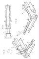
- a fine spinning machine frame 2 is provided beside a winder 1 and is positioned on a straight line extending in the longitudinal direction of the winder 1.
- Conveyors 3a and 3b as tray-carrying routes are provided at each side of the fine spinning machine frame 2 in the width direction and extend along the length of the fine spinning machine frame 2.
- the conveyors 3a and 3b comprise guiding rails 5a (as shown in Fig.
- a full bobbin-carrying route 7 and an empty bobbin-carrying route 8 are provided at the sides of the winder 1; the full bobin-carrying route 7 is provided at the portion opposite to the exit of the conveyor 3a, and the empty bobbin-carrying route 8 is provided at the portion opposite to the entrance of the conveyor 3b, of the winder 1.
- a bobbin carrier 9 is provided between an outer end side O.E. of the fine spinning machine frame 2 and the winder 1 and delivers the full bobbins F and the empty bobbins E respectively between the conveyor 3a and the full bobbin-carrying route 7, and between the conveyor 3b and the empty bobbin-carrying route 8.
- the bobbin carrier 9 has a belt 10 to carry the peg trays 4.
- the belt 10 is driven by a motor 13 and is wound around a driving pulley 11 and many guiding pulleys 12 to form substantially three portions of running route; one is the portions adjacent to the ends of both the conveyors 3a and 3b and to the ends of both the full-wound and empty bobbin-carrying routes 7 and 8, where the belt 10 runs horizontally, in the direction crossing both the conveyors 3a and 3b and/or both the full-wound and empty bobbin-carrying routes 7 and 8, at almost the same height as them; another is the portions where the belt 10 runs vertically inside the conveyors 3a and 3b and/or inside the full-wound and empty bobbin-carrying routes 7 and 8; and the other is the portions where the belt 10 runs horizontally, in the longitudinal direction of the fine spinning machine frame 2, above a passage between the winder 1 and the fine spinning machine frame 2.
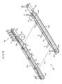
- a pair of linear guiding members 14 are provided running along the belt 10 from the portion corresponding to the end of the conveyor 3a to the portion corresponding to the end of the full bobbin-carrying route 7, putting the pegs 4a of the peg trays 4 therebetween and elastically pressing the trays 4b of the peg trays 4 against the belt 10.
- a pair of linear guiding members 15 are also provided running along the belt 10 from the portion corresponding to the end of the other conveyor 3b to the portion corresponding to the end of the empty bobbin-carrying route 8, elastically pressing the trays 4b of the peg trays 4 cooperating with the belt 10.
- Both the guiding members 14 and 15 are provided so as to make the posture of the empty bobbins E and/or the full bobbins F, which are fitted to the peg trays 4 moving with the belt 10, substantially horizontal except at the portions adjacent to the ends of the conveyors 3a and 3b and to the ends of the full-wound and empty bobbin-carrying routes 7 and 8.
- a flat belt as one form of the belt 10 comprises a sliding core band 10a made of nylon of low friction and a rubber layer 10b of high friction.
- the sliding core band 10a and the rubber layer 10b are laminated and one end of the sliding core band 10a is protruded from the rubber layer 10b.
- the peg trays 4 move with the belt 10 while the bottom surfaces of the peg trays 4 are pressed against the rubber layer 10b of the belt 10.
- the peg trays 4 are carried while having cantact with the rubber layer 10b of the belt 10 at the opposite side of the protruding portion of the sliding core belt 10a.
- pairs of guiding segments 16 which guide the belt 10 while putting the belt 10 therebetween are arranged along the belt 10 at the predetermined intervals.
- plate springs 17 which have contact with the sliding core band 10a to elastically press the belt 10 in its width direction, namely, toward the guiding members 14 and 5 are provided at the predetermined intervals.
- Supporting segments 20 to which the guiding members 14 and 15 are attached and fixed to supporting brackets 21 by means of bolts 22 while the positions of the supporting segments 20 can be adjustable in the direction shown as an arrow in Fig. 5 (a).
- the plate springs 17 do not have direct contact with the sliding core band 10, but have indirect contact with the sliding core band 10 via contact portions 17a made of antifriction members such as ceramics. Even though the pressing direction of the plate springs 17 is the width direction of the belt 10, the belt 10 will not fall off from the guiding pulleys 12 because the moving amount of the belt 10 by the plate spings 17 is little.
- a guiding segment 16 and a supporting segment 20 can also be formed integrally.
- One ends, which correspond to the conveyors 3a and 3b, of the guiding members 14 and 15 are formed respectively extending above the guiding rails 5a of the conveyors 3a and 3b as shown in Figs. 3 (a) and 3 (b), so that the delivery of the peg trays 4 can be easily done between the conveyors 3a and 3b and the bobbin carrier 9.
- the other ends, which correspond to the full bobbin-carrying route 7 and to the empty bobbin-carrying route 8, of the guiding members 14 and 15 are also formed respectively extending above the guiding rails (not shown) of the full bobbin-carrying route 7 and of the empty bobbin-carrying route 8.
- the full bobbins F After finishing changing bobbins in accordance with the full bobbin stop of the machine frame, the full bobbins F are fitted to the peg trays 4 and it is ready to carry out the full bobbins F and to carry in the empty bobbins E. Then, after the winder 1 emits a full bobbin request signal, the full bobbins F start being carried out from the fine spinning machine frame 2, and also the empty bobbins E start being carried into the machine frame 2.
- One conveyor 3a is driven in the direction in which the peg trays 4 are carried toward the outer end O.E.
- the other conveyor 3b is driven in the direction in which the peg trays 4 are carried toward the gear end G.E. Accordingly, the peg trays 4 on the conveyor 3b are sent to the conveyor 3a via the connecting rail 6.
- the peg trays 4 inserted into the full bobbins F are successively transferred onto the belt 10 of the bobbin carrier 9, guided by the guiding members 14. Then, the peg trays 4 are tilted in the same direction as the longitudinal direction of the fine spinning machine frame 2 by means of the guiding members 14 and the posture of the full bobbins F on the peg trays 4 are changed into the horizontal ones.
- the direction of the full bobbins F is changed so as to cross the longitudinal direction of the fine spinning machine frame 2 and the full bobbins F are carried toward the winder 1 while keeping the same changed direction as just described above.
- the direction of the full bobbins F is again changed into the same one as the longitudinal direction of the machine frame 2, and the full bobbins F are carried down to the same height as the full bobbin-carrying route 7 while keeping the same changed direction as just described above.
- the peg trays 4 inserted into the empty bobbins 4 which have been used at the winder 1 are carried from the empty bobbin-carrying route 8 onto the belt 10 of the bobbin carrier 9 while being guided by the guiding members 15.
- the peg trays 4 carried onto the belt 10 with the empty bobbins E being in the vertical posture are tilted in the longitudinal direction of the fine spinning machine frame 2 to make the posture of the empty bobbins E horizontal and move with the belt 10.
- the direction of the empty bobbins E is changed outside to cross the longitudinal direction of the fine spinning machine frame 2, and then the peg trays 4 inserted into the empty bobbins E are carried toward the fine spinning machine frame 2.
- the posture of the empty bobbin E is again changed into the longitudinal direction of the fine spinning machine frame 2 and the empty bobbins E are carried to the same height as the conveyor 3b.
- the posture of the empty bobbins E is again changed into the vertical direction by means of the guiding members 15, and the peg trays 4 are then carried onto the conveyor 3b.
- the peg trays 4 inserted into the empty bobbins E which are carried onto the conveyor 3b via the bobbin carrier 9 are sent onto the conveyor 3a via the connecting rail 6.
- the conveyance of the front peg tray 4 is restricted by means of a stopper (no shown).
- the following peg trays 4 successively come to be positioned at the front portion of the spindle rail while having contact with one another.
- a counter (not shown) is provided at the gear end side G.E. of the conveyor 3b, and a stopper (not shown) at the predetermined position of the gear end side G.E.
- the peg trays 4 supporting the empty bobbins E are successively positioned corresponding to a spindle row.
- a full bobbin sensor (not shown) is provided at the end of the conveyor 3a, and an empty bobbin sensor (not shown) is provided at the end of the empty bobbin-carrying route 8. Both the sensors respectively count the number of the full bobbins F and the empty bobbins E which are carried onto the bobbin carrier 9.
- the drive of the motor 13 stops to finish carrying out the full bobbins F and to finish carrying in the empty bobbins E.
- the manufacturing cost of the apparatus can be lower because only the one motor is required for the one belt which can carry in and out each the empty and full bobbins E and F, as described above.
- the full bobbins F and the empty bobbins E are carried in the substantially horizontal posture at the portion where the belt 10 runs horizontally near below a ceiling, so that it is not necessary to have a large amount of space between the belt 10 and the ceiling, and that even under a low ceiling the conveyance of the bobbins can be done easily.
- a belt 40 of a bobbin carrier 39 runs inside an underground pit 18 provided at the floor between the winder 1 and the fine spinning machine frame 2 in the apparatus of the second embodiment.
- the belt 40 is hooked around many guiding pulleys 42, and those of the guiding pulleys 42 which are provided adjacent to the fine spinning machine frame 2 and to the winder 1 are arranged to make the supporting shafts thereof vertical.
- the guiding pulleys 42 which are provided inside the underground pit 18 and/or adjacent to the underground pit 18 beside the fine spinning machine frame 2 are arranged to make the supporting shafts thereof horizontal and to make the interval between two parallel running routes of the belt 40 running inside the underground pit 18 narrower than the interval between the conveyors 3a and 3b and/or the interval between the full bobbin-carrying route 7 and the empty bobbin-carrying route 8.
- Guiding members 44 and 45 are provided along the belt 40 to make the posture of the empty bobbins E and of the full bobbins F fitted to the peg trays 4 project outward and be substantially horizontal when the peg trays 4 are carried inside the underground pit 18.
- the bobbin carrier 39 drives to carry the full bobbins F out of the fine spinning machine frame 2 and to carry the empty bobbins E to the frame 2
- the peg trays 4 inserted into the full bobbins F are, while keeping the substantially vertical posture, carried onto the belt 40 of the bobbin carrier 39 and move with the belt 40.
- the posture of the full bobbins F is changed to project substantially horizontally outside of the belt 40, and the peg trays 4 move inside the underground pit 18 toward the winder 1 while keeping the horizontal posture just described above.
- the full bobbins F After getting out of the underground pit 18, the full bobbins F are changed into the vertical posture before coming to the portion correspond to the end of the full bobbin-carrying route 7, and are carried onto the full bobbin-carryig route 7 in the vertical posture.
- the posture of the empty bobbins E is changed to project horizontally outside of the belt 40 on the way to the underground pit 18, and the peg trays 4 move inside the underground pit 18 while keeping the above-described posture.
- the empty bobbins E After getting out of the underground pit 18, the empty bobbins E again come to be in the vertical posture and are carried onto the conveyor 3b in the same posture. Accordingly, the depth of the underground pit 18 can be small because the empty bobbins E and the full bobbins F are conveyed in the substantially horizontal posture inside the underground pit 18. Moreover, the guiding pulleys 42 are provided to narrow the interval between the running routes of the belt 40 inside the underground pit 18, so that the width of the underground pit 18 can be small and the installation cost will be lower.
- the first and second embodiments can be modified as below; for example, a bobbin carrier 49 can be positioned on the floor between the winder 1 and the fine spinning machine frame 2 as shown in Fig. 9.
- the belt 10 and the guiding members 14 and 15 are provided in order that the interval of the running routes of the belt 10 between the winder 1 and the fine spinning machine frame 2 running in the longitudinal direction of the frame 2 might be narrow and that the empty bobbins E and/or the full bobbins F might be carried in the substantially horizontal posture. Therefore, both the height and width of a step 19 on which an operator can walk above the bobbin carrier 49 can be small, so that the operator can pass therethrough easily.
- a bobbin carrier 59 which is substantially the same as the one in the first embodiment can be used.
- a bobbin carrier 60 comprises a pair of carriers 61a and 61b which are respectiely provided between the exit side of the conveyor 3a and the entrance side of the full bobbin-carrying route 7 of the winder 1 and between the entrance side of the conveyor 3b and the exit side of the empty bobbin-carrying route 8 of the winder 1, and which extend in the longitudinal direction of the fines spinning machine frame 2.
- both the carriers 61a and 61b are constituted so that endless belts 64 which are hooked around driving pulleys 62a and 62b and around driven pulleys 63a and 63b run inside an underground pit 65 installed at the floor between the winder 1 and the fine spinning machine frame 2.
- the driving pulleys 62a and 62b driven by a motor M are provided adjacent to the ends of both the conveyors 3a and 3b, and the driven pulleys 63a and 63b are provided adjacent to the ends of the full bobbin-carrying route 7 and of the empty bobin-carrying route 8.
- the upper surfaces of the driving pulley 62a and of the driven pulley 63b are positioned lower than the upper surfaces of the belt conveyor 5b and of the empty bobbin-carrying route 8 respectively.
- the upper surfaces of the driving pulley 62b and the driven pulley 63a are positioned higher than the upper surfaces of the belt canveyor 5b and of the full bobbin-carrying route 7 respectively.
- Guiding plates 66 are provided between the upper surfaces of the pulleys 62a, 62b, 63a, 63b and the upper surfaces of the belt conveyor 5b and of the bobbin-carrying routes 7, 8 to make the front sides thereof lower than the other sides in the running direction of the peg trays 4.
- the plural guiding pulleys 67 which guide the belt 64 to run inside the underground pit 65 are provided inside the underground pit 65 having the axis thereof extend in the horizontal direction.
- a pair of linear guiding members 68 are provided along the upper running route of the belt 64 from the portion corresponding to the end of the conveyor 3a to the portion corresponding to the end of the full bobbin-carrying route 7 in order to put the pegs 4a of the peg trays 4 therebetween and in order to press the peg trays 4 cooperating with the belt 64 elastically.
- a pair of linear guiding members 69 are also provided along the upper running route of the belt 64 from the portion corresponding to the end of the conveyor 3b to the portion corresponding to the end of the empty bobbin-carrying route 8 in order to press the peg trays 4 elastically cooperating with the belt 64.
- Both the guiding members 68 and 69 are arranged to make the posture of the empty bobbins E and of the full bobbins F tilted inside and be substantially horizontal at any other places except for the places adjacent to the ends of the conveyor 3a and 3b, to the end of the full bobbin-carrying route 7, and to the end of the empty bobbin-carrying route 8.
- Both the guiding members 68 and 69 are provided not to have contact with the upper surfaces of the peg trays 4 at the portions corresponding to the guiding plates 66 in order that the peg trays 4 might be able to slide down on each guiding plate 66 by their own weights.
- the ends, which correspond to the conveyors 3a and 3b, of the guiding members 68 and 69 are formed to extend above the guiding rails 5a of the coneyors 3a and 3b as shown in Figs. 13 (a), 13 (b) and 14, so that the conveyance of the peg trays 4 between the conveyors 3a, 3b and the bobbin carrier 60 might be able to be done easily.
- the ends, which correspond to the full bobbin-carrying route 7 and to the empty bobbin-carrying route 8, of the guiding members 68 and 69 are also formed to extend respectively above the guiding rails (not shown) of the full bobbin-carrying route 7 and of the empty bobbin-carrying route 8.
- the peg trays 4 inserted into the full-wound bobbins F on the conveyor 3a are successively carried onto the belt 64 of the carrier 61a, and then are tilted inside in the horizontal posture by means of the guiding members 68 to be carried toward the winder 1.
- the posture of the peg trays 4 is again changed vertically by means of the guiding members 68, and then the peg trays 4 are carried onto the full-wound bobbin-carrying route 7.
- the peg trays 4 inserted into the empty bobbins E which have been used at the winder 1 are transferred from the empty bobbin-carrying route 8 to the belt 64 of the carrier 61b guided by the guiding members 69 and the guiding plate 66.
- the peg trays 4 which are carried onto the belt 64 having the posture of the empty bobbins E vertical are turned to be horizontal projected toward the inside of the underground pit 65 by means of the guiding mambers 69 and move with the belt 64.
- the empty bobbins E are again turned to be vertical by means of the guiding members 69 and the peg trays 4 inserted into the empty bobbins E are carried onto the conveyor 3b.
- the posture of the full-wound bobbins F and of the empty bobbins E is changed horizontal being projected toward the inside of both the carriers 61a and 61b and are carried in the horizontal posture, so that a large amount of space is not necessary above the belt 64 for the conveyance of the bobbins. Accordingly, the depth of the underground pit 65 can be small, and the width of the pit 65 is not required to be large.
- the guiding plates 66 are provided, between the driving pulleys 62a, 62b, the driven pulleys 63a, 63b and the conveyors 3a, 3b, the bobbin-carrying routes 7, 8, while having the front portion thereof lower in the running direction of the peg trays 4, so that the conveyance of the peg trays 4 can be done easily even if the diameter of the pulleys 62a, 62b, 63a, and 63b is larger than the diameter of the peg trays 4.
- the present embodiment can be modified as described below; for instance, the carriers 61a and 61b can be constituted in the way shown in Fig. 15 so that the runnig route of the belt 64 before coming to the portion where the belt runs horizontally in the underground pit 65 might be substantially vertical.
- the extra space for the bobbin conveyance has to be prepared before the underground pit 65 when the running route of the belt 64 is made to be tilted to the portion where the belt 64 runs horizontally like the aforementioned third embodiment, but if the apparatus is constituted like the modified example as described above, the space before the underground pit 65 can be very small.
- the carriers 61a and 61b instead of installing the underground pit 65, can be positioned on the floor.
- the empty bobbins E and the full-wound bobbins F are also carried in the horizontal posture projected inside facing each other, so that the height of a step 75 on which an operator can pass through above the bobbin carrier 60 might be small.
- the guiding plates 66 which are positioned at the connecting portions between the conveyor 3a and the carrier 61a and between the empty bobbin-carrying route 8 and the carrier 61b, can also be provided to be tilted lower inside as shown in Fig. 17.
- the peg trays 4 move from the conveyor 3a and/or the empty bobbin-carrying route 8 onto the belt 64 of the carriers 61a and 61b sliding on the guiding plates 66, peg trays 4 are carried to make the full-wound bobbins F and the empty bobbins E tilted lower inside on the guiding plates 66 and the posture of the bobbins can be easily changed.
- the guiding plates 66 can be omitted by having the upper surface of the driving and driven pulleys 62a, 62b, 63a, and 63b and those of the full-wound and empty bobbin-carrying routes 7 and 8 at the same height and by making the diameters of the pulleys smaller.
- a bobbin-carrying apparatus to carry peg trays which have a tray and a peg protruded on one surface of the tray to support bobbins between conveyors provided at a fine spinning machine and bobbin-carrying routes provided at a winder.
- the bobbin-carrying apparatus comprises belts provided between the conveyors and the bobbin-carrying routes, pulleys guiding and supporting the belts, motors driving the belts functionally connected with the belts, and a pair of linear guiding members extending along the belts having the pegs of the peg trays therebetween.
- the belts carry the peg trays pressing the trays cooperating with the guiding members.
- the guiding members are provided relative to the belts so that the peg trays are carried while the pegs are arranged in the horizontal posture between the fine spinning machine and the winder.
Landscapes
- Engineering & Computer Science (AREA)
- Mechanical Engineering (AREA)
- Textile Engineering (AREA)
- Spinning Or Twisting Of Yarns (AREA)
- Replacing, Conveying, And Pick-Finding For Filamentary Materials (AREA)
Applications Claiming Priority (4)
| Application Number | Priority Date | Filing Date | Title |
|---|---|---|---|
| JP14862488A JPH01314737A (ja) | 1988-06-16 | 1988-06-16 | 精紡ワインダのボビン搬送装置 |
| JP79719/88U | 1988-06-16 | ||
| JP148624/88 | 1988-06-16 | ||
| JP7971988U JPH0613274Y2 (ja) | 1988-06-16 | 1988-06-16 | 精紡ワインダのボビン搬送装置 |
Publications (2)
| Publication Number | Publication Date |
|---|---|
| EP0346910A1 true EP0346910A1 (de) | 1989-12-20 |
| EP0346910B1 EP0346910B1 (de) | 1994-12-14 |
Family
ID=26420720
Family Applications (1)
| Application Number | Title | Priority Date | Filing Date |
|---|---|---|---|
| EP89110907A Expired - Lifetime EP0346910B1 (de) | 1988-06-16 | 1989-06-15 | Einrichtung zum Transport von Spulen in einer mit einer Spulmaschine kombinierten Spinnmaschine |
Country Status (4)
| Country | Link |
|---|---|
| US (1) | US5074401A (de) |
| EP (1) | EP0346910B1 (de) |
| DE (1) | DE68919916T2 (de) |
| ES (1) | ES2065943T3 (de) |
Cited By (10)
| Publication number | Priority date | Publication date | Assignee | Title |
|---|---|---|---|---|
| DE4024163A1 (de) * | 1989-07-28 | 1991-02-07 | Murata Machinery Ltd | Spinnspulenfoerdervorrichtung |
| DE4015173A1 (de) * | 1990-05-11 | 1991-11-14 | Schlafhorst & Co W | Transportsystem fuer auf unabhaengige einzeltraeger senkrecht aufgesetzte spulen oder spulenhuelsen zwischen in der hoehe unterschiedlichen transportebenen |
| EP0462417A1 (de) * | 1990-06-12 | 1991-12-27 | Maschinenfabrik Rieter Ag | Spinnmaschine, insbesondere Ringspinnmaschine |
| DE4124061A1 (de) * | 1990-07-20 | 1992-01-23 | Murata Machinery Ltd | Foerdervorrichtung |
| DE4137743A1 (de) * | 1990-11-16 | 1992-05-21 | Murata Machinery Ltd | Transportanlage fuer spulenhuelsen |
| DE4041712A1 (de) * | 1990-12-24 | 1992-06-25 | Schlafhorst & Co W | Automatische spulmaschine |
| DE4200889A1 (de) * | 1991-01-18 | 1992-07-23 | Murata Machinery Ltd | Vorrichtung zum transportieren von spulentellern |
| DE19915472A1 (de) * | 1999-04-06 | 2000-10-12 | Schlafhorst & Co W | Vorrichtung zum Transportieren von Spinnspulen und/oder Spulenhülsen |
| DE19931982A1 (de) * | 1999-07-09 | 2001-01-11 | Schlafhorst & Co W | Transportvorrichtung für Transportpaletten |
| CH710527A1 (de) * | 2014-12-16 | 2016-06-30 | Rieter Ag Maschf | Spinnmaschine. |
Families Citing this family (5)
| Publication number | Priority date | Publication date | Assignee | Title |
|---|---|---|---|---|
| DE4038628A1 (de) * | 1990-12-04 | 1992-06-11 | Schlafhorst & Co W | Zwischen einer spulmaschine und einer kopslieferstelle angeordnete vorrichtung zum abziehen von auf einzeltraeger aufgesteckten spulenhuelsen |
| FR2697235B1 (fr) * | 1992-10-23 | 1995-01-27 | Gallay Sa Jean | Procédé et dispositif pour véhiculer des objets le long d'un circuit et utilisation de ce dispositif. |
| DE4434714C2 (de) * | 1994-09-28 | 1996-10-17 | Froreich Andre Von | Fördersystem |
| US7530448B2 (en) * | 2006-09-14 | 2009-05-12 | Northern Plastics Ltd. | Transfer chain with a lug and cap mounted thereon |
| CN108081111B (zh) * | 2018-01-24 | 2023-11-17 | 佛山市镱发科技有限公司 | 圆管自动送料台 |
Citations (2)
| Publication number | Priority date | Publication date | Assignee | Title |
|---|---|---|---|---|
| DE3616880A1 (de) * | 1985-05-20 | 1986-11-20 | Murata Kikai K.K., Kyoto | Vorrichtung zum foerdern von spulen |
| DE3630670A1 (de) * | 1985-09-09 | 1987-04-30 | Murata Machinery Ltd | Spulenfoerdereinrichtung zum transportieren von spinnspulen |
Family Cites Families (6)
| Publication number | Priority date | Publication date | Assignee | Title |
|---|---|---|---|---|
| JPS6050665A (ja) * | 1983-08-29 | 1985-03-20 | Hitachi Ltd | デ−タ記録再生方式 |
| JPH0659977B2 (ja) * | 1986-02-05 | 1994-08-10 | 日清紡績株式会社 | 管糸ボビンの搬送装置 |
| JPH06465Y2 (ja) * | 1987-10-27 | 1994-01-05 | 株式会社豊田自動織機製作所 | ペッグトレイ搬送装置 |
| US4842206A (en) * | 1987-12-21 | 1989-06-27 | Murata Kikai Kabushiki Kaisha | Automatic yarn end finding device for a spinning bobbin |
| CA2002597C (en) * | 1988-11-14 | 1999-03-23 | Thomas M. Eckrich | Solvates of b-lactam antibiotic |
| JPH02191304A (ja) * | 1989-12-16 | 1990-07-27 | Rohm Co Ltd | チップ抵抗器の製造方法 |
-
1989
- 1989-06-12 US US07/365,012 patent/US5074401A/en not_active Expired - Fee Related
- 1989-06-15 EP EP89110907A patent/EP0346910B1/de not_active Expired - Lifetime
- 1989-06-15 DE DE68919916T patent/DE68919916T2/de not_active Expired - Fee Related
- 1989-06-15 ES ES89110907T patent/ES2065943T3/es not_active Expired - Lifetime
Patent Citations (2)
| Publication number | Priority date | Publication date | Assignee | Title |
|---|---|---|---|---|
| DE3616880A1 (de) * | 1985-05-20 | 1986-11-20 | Murata Kikai K.K., Kyoto | Vorrichtung zum foerdern von spulen |
| DE3630670A1 (de) * | 1985-09-09 | 1987-04-30 | Murata Machinery Ltd | Spulenfoerdereinrichtung zum transportieren von spinnspulen |
Cited By (11)
| Publication number | Priority date | Publication date | Assignee | Title |
|---|---|---|---|---|
| DE4024163A1 (de) * | 1989-07-28 | 1991-02-07 | Murata Machinery Ltd | Spinnspulenfoerdervorrichtung |
| DE4015173A1 (de) * | 1990-05-11 | 1991-11-14 | Schlafhorst & Co W | Transportsystem fuer auf unabhaengige einzeltraeger senkrecht aufgesetzte spulen oder spulenhuelsen zwischen in der hoehe unterschiedlichen transportebenen |
| EP0455989A3 (en) * | 1990-05-11 | 1991-12-27 | W. Schlafhorst & Co. | Transport system between different levels of height for bobbins or bobbin tubes put in an upright position on independant supports |
| EP0462417A1 (de) * | 1990-06-12 | 1991-12-27 | Maschinenfabrik Rieter Ag | Spinnmaschine, insbesondere Ringspinnmaschine |
| DE4124061A1 (de) * | 1990-07-20 | 1992-01-23 | Murata Machinery Ltd | Foerdervorrichtung |
| DE4137743A1 (de) * | 1990-11-16 | 1992-05-21 | Murata Machinery Ltd | Transportanlage fuer spulenhuelsen |
| DE4041712A1 (de) * | 1990-12-24 | 1992-06-25 | Schlafhorst & Co W | Automatische spulmaschine |
| DE4200889A1 (de) * | 1991-01-18 | 1992-07-23 | Murata Machinery Ltd | Vorrichtung zum transportieren von spulentellern |
| DE19915472A1 (de) * | 1999-04-06 | 2000-10-12 | Schlafhorst & Co W | Vorrichtung zum Transportieren von Spinnspulen und/oder Spulenhülsen |
| DE19931982A1 (de) * | 1999-07-09 | 2001-01-11 | Schlafhorst & Co W | Transportvorrichtung für Transportpaletten |
| CH710527A1 (de) * | 2014-12-16 | 2016-06-30 | Rieter Ag Maschf | Spinnmaschine. |
Also Published As
| Publication number | Publication date |
|---|---|
| US5074401A (en) | 1991-12-24 |
| ES2065943T3 (es) | 1995-03-01 |
| DE68919916T2 (de) | 1995-05-18 |
| EP0346910B1 (de) | 1994-12-14 |
| DE68919916D1 (de) | 1995-01-26 |
Similar Documents
| Publication | Publication Date | Title |
|---|---|---|
| US5074401A (en) | Bobbin-carrying apparatus of a combined fine spinning machine and winder | |
| US5040669A (en) | Duplex conveyor | |
| US4683713A (en) | Bobbin feeding system | |
| US5011000A (en) | Bobbin carrier in spinning machine | |
| JPS6260774A (ja) | ボビン搬送装置 | |
| US4784255A (en) | Spinning bobbin transporting device | |
| US5301497A (en) | Device for conveying full and empty bobbins between multi-position textile machines | |
| GB2299065A (en) | Can-handling system in a textile installation | |
| JPH0613274Y2 (ja) | 精紡ワインダのボビン搬送装置 | |
| JPH06465Y2 (ja) | ペッグトレイ搬送装置 | |
| US5136834A (en) | Apparatus for transporting bobbin tubes of a textile machine | |
| EP0409624B1 (de) | Vorrichtung zur Übergabe von Spulen in Spinnmaschinen | |
| US5177949A (en) | Apparatus for transporting bobbin tubes of a textile machine | |
| JPS61160433A (ja) | ボビン装填装置 | |
| JPH01314737A (ja) | 精紡ワインダのボビン搬送装置 | |
| US5845760A (en) | Cheese conveying system | |
| JPH07304569A (ja) | 紡機におけるボビン搬送方法及び装置 | |
| JPH0441190Y2 (de) | ||
| JPH0613198Y2 (ja) | エレベ−タ型ソ−タにおける用紙のガイド機構 | |
| JPH0643064Y2 (ja) | 仕分けコンベヤ装置 | |
| JP2757223B2 (ja) | 自動ワインダーのボビン搬送ラインとこのラインに用いる垂直コンベア | |
| JPH022783B2 (de) | ||
| JPH0441189Y2 (de) | ||
| JPH02289133A (ja) | 精紡ワインダ | |
| JP2513200B2 (ja) | 精紡機等における空ボビン位置決め方法 |
Legal Events
| Date | Code | Title | Description |
|---|---|---|---|
| PUAI | Public reference made under article 153(3) epc to a published international application that has entered the european phase |
Free format text: ORIGINAL CODE: 0009012 |
|
| 17P | Request for examination filed |
Effective date: 19890615 |
|
| AK | Designated contracting states |
Kind code of ref document: A1 Designated state(s): CH DE ES IT LI |
|
| 17Q | First examination report despatched |
Effective date: 19911219 |
|
| GRAA | (expected) grant |
Free format text: ORIGINAL CODE: 0009210 |
|
| AK | Designated contracting states |
Kind code of ref document: B1 Designated state(s): CH DE ES IT LI |
|
| REF | Corresponds to: |
Ref document number: 68919916 Country of ref document: DE Date of ref document: 19950126 |
|
| ITF | It: translation for a ep patent filed | ||
| REG | Reference to a national code |
Ref country code: ES Ref legal event code: FG2A Ref document number: 2065943 Country of ref document: ES Kind code of ref document: T3 |
|
| PLBE | No opposition filed within time limit |
Free format text: ORIGINAL CODE: 0009261 |
|
| STAA | Information on the status of an ep patent application or granted ep patent |
Free format text: STATUS: NO OPPOSITION FILED WITHIN TIME LIMIT |
|
| 26N | No opposition filed | ||
| PGFP | Annual fee paid to national office [announced via postgrant information from national office to epo] |
Ref country code: CH Payment date: 19990614 Year of fee payment: 11 |
|
| PGFP | Annual fee paid to national office [announced via postgrant information from national office to epo] |
Ref country code: DE Payment date: 19990618 Year of fee payment: 11 |
|
| PGFP | Annual fee paid to national office [announced via postgrant information from national office to epo] |
Ref country code: ES Payment date: 19990621 Year of fee payment: 11 |
|
| PG25 | Lapsed in a contracting state [announced via postgrant information from national office to epo] |
Ref country code: ES Free format text: THE PATENT HAS BEEN ANNULLED BY A DECISION OF A NATIONAL AUTHORITY Effective date: 20000616 |
|
| PG25 | Lapsed in a contracting state [announced via postgrant information from national office to epo] |
Ref country code: LI Free format text: LAPSE BECAUSE OF NON-PAYMENT OF DUE FEES Effective date: 20000630 Ref country code: CH Free format text: LAPSE BECAUSE OF NON-PAYMENT OF DUE FEES Effective date: 20000630 |
|
| REG | Reference to a national code |
Ref country code: CH Ref legal event code: PL |
|
| PG25 | Lapsed in a contracting state [announced via postgrant information from national office to epo] |
Ref country code: DE Free format text: LAPSE BECAUSE OF NON-PAYMENT OF DUE FEES Effective date: 20010403 |
|
| REG | Reference to a national code |
Ref country code: ES Ref legal event code: FD2A Effective date: 20020204 |
|
| PG25 | Lapsed in a contracting state [announced via postgrant information from national office to epo] |
Ref country code: IT Free format text: LAPSE BECAUSE OF NON-PAYMENT OF DUE FEES Effective date: 20050615 |