EP0346885B2 - Dispositif pour l'attelage d'une remorque à un véhicule - Google Patents
Dispositif pour l'attelage d'une remorque à un véhicule Download PDFInfo
- Publication number
- EP0346885B2 EP0346885B2 EP89110825A EP89110825A EP0346885B2 EP 0346885 B2 EP0346885 B2 EP 0346885B2 EP 89110825 A EP89110825 A EP 89110825A EP 89110825 A EP89110825 A EP 89110825A EP 0346885 B2 EP0346885 B2 EP 0346885B2
- Authority
- EP
- European Patent Office
- Prior art keywords
- shaped support
- support member
- vehicle
- locking
- tail region
- Prior art date
- Legal status (The legal status is an assumption and is not a legal conclusion. Google has not performed a legal analysis and makes no representation as to the accuracy of the status listed.)
- Expired - Lifetime
Links
Images


Classifications
-
- B—PERFORMING OPERATIONS; TRANSPORTING
- B60—VEHICLES IN GENERAL
- B60D—VEHICLE CONNECTIONS
- B60D1/00—Traction couplings; Hitches; Draw-gear; Towing devices
- B60D1/14—Draw-gear or towing devices characterised by their type
- B60D1/141—Arrangements or frames adapted to allow the connection of trailers to tractor three-point hitches
-
- B—PERFORMING OPERATIONS; TRANSPORTING
- B60—VEHICLES IN GENERAL
- B60D—VEHICLE CONNECTIONS
- B60D1/00—Traction couplings; Hitches; Draw-gear; Towing devices
- B60D1/24—Traction couplings; Hitches; Draw-gear; Towing devices characterised by arrangements for particular functions
- B60D1/42—Traction couplings; Hitches; Draw-gear; Towing devices characterised by arrangements for particular functions for being adjustable
- B60D1/46—Traction couplings; Hitches; Draw-gear; Towing devices characterised by arrangements for particular functions for being adjustable vertically
- B60D1/465—Traction couplings; Hitches; Draw-gear; Towing devices characterised by arrangements for particular functions for being adjustable vertically comprising a lifting mechanism, e.g. for coupling while lifting
Definitions
- the invention relates to a device for coupling a trailer to a vehicle according to the preamble of claim 1.
- a device of this type is known from DE-A-1455504.
- EP-A 0184489 it is known to attach a carrier shaft of a coupling hook, at the end facing away from the coupling hook, a coupling member of a different design, to a carrier of a device of a similar type, so that either the coupling hook or the other Way trained coupling member protrudes to the rear.
- the object of the invention is to provide a device according to the preamble of claim 1, in which a simple implementation of a support shaft formed with different coupling members is possible with great fastening reliability, the pivoting movement of the coupling member not being impaired.
- an embodiment according to claim 2 is preferably provided.
- the lifting and lowering of the coupling member is facilitated by the training according to claim 3 with additional guidance.
- an embodiment according to claim 4 is preferably provided.
- training according to claim 5 is preferably provided.
- an embodiment according to claim 6 is preferably provided.
- an embodiment according to claim 9 is preferably provided.
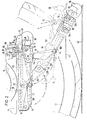
- Fig. 1 shows the rear part of a tractor in side view with the coupling member raised.
- Fig. 2 shows an enlarged view of the lower rear part of the tractor according to Fig. 1 in a side view with the coupling member lowered.
- Fig. 3 shows the middle lower area of the tractor from behind with the coupling member lowered.
- the tractor 2 has a chassis 4 on which a gearbox and bearing housing 6 for a continuous rear wheel axle 8 are attached, at the free ends of which wheels 10, 12 are seated.
- the axis 8 is guided on both sides of the housing 6 through bearing flanges 14.
- a box 16 with a U-shaped cross section and open at the bottom is fastened by means of screws 18.
- two rear links 26 and two front links 28 are articulated on the box on a common pivot axis 22 and 24, respectively.
- the longitudinal legs 30, 32 of a U-beam 34 are articulated, on the transverse legs 36 of which a rear-facing coupling member 38 in the form of a hook open at the top is attached.
- the links 26, 28 are dimensioned in such a way that the U-beam 34 extends from a raised position (FIGS. 1 and 2) in which it extends horizontally under the box 16 on both sides and in which the coupling member 38 is close to the rear 40 of the tractor is in a lowered position (Fig. 2 and 3) can be transferred, in which the U-beam 34 extends obliquely backwards downwards and the coupling member 38 lies on or near the driving surface 42.
- the U-bracket 34 can be raised and lowered in the manner described by means of a lifting and lowering device 46 to be driven by a hydraulic motor 44.
- a releasable locking device 48 is provided for locking the U-beam 34 in the raised position.
- cover 50 for covering the coupling member 38 in the raised position and for securing a mating coupling member coupled to the coupling member 38, for example an eyelet on a pull rod.
- the cover 50 has a recess 51 in the center in its rear lower edge for receiving the nose 39 of the coupling hook 38.
- the lifting and lowering device 46 has lifting and lowering rods 52, 54 articulated on the outer sides of the rear ends of the longitudinal legs 30, 32 of the U-beam 34, the free ends of which via lever linkages 56, 58 having the ends of an output shaft 60 of the hydraulic motor 44 are connected.
- the hydraulic motor 44 thus serves as a lifting and lowering motor. It is screwed onto the top of the housing 6. Every lever linkage consists of a one-armed lever 62 which is articulated via a connecting piece 64 to one of the flanges 14 and at the free end of which one of the lifting and lowering rods 52, 54 is articulated.
- a link 66 is articulated to the central region of each one-armed lever 62.
- the effective length of the handlebar is adjustable by a slot guide 68 for a fixing screw 70, whereby the stroke of the lever linkage 56 or 58 is adjustable.
- the other end of the link 66 is articulated on an arm 72 which sits on the respective end of the output shaft 60.
- the lengths of the lifting and lowering rods 52, 54 are also adjustable.
- a forwardly opening locking hook 74 is articulated above the longitudinal legs 30, 32 of the U-beam 34 to engage under a locking bolt 76 at the rear end of each longitudinal leg 30, 32 of the U-beam 34.
- the two locking hooks 74 sit on the ends of a shaft 78 common to them, which is supported in blocks 80 on the top of the box 16 and is resiliently biased in the locking position of the locking hooks 74 by a helical spring 82 which wraps around them.
- This Bowden cable 88 is supported by a bracket 90 on the rear of the vehicle.
- the core 86 is fastened to an actuating lever 92, which can be operated by the driver on the rear of the tractor 2.
- the locking bolts 76 are provided with side and rear covers 94, 96 which are attached to the U-beam 34.
- the lifting and lowering rods 52, 54 are hinged to sections 98 of the locking bolts 76 which protrude from the side covers 94.
- the U-beam 34 is covered on the underside with a plate 100, so that the U-beam 34 and plate 100 form a box open at the top.
- a support shaft 102 of the coupling hook 38 is fastened to the plate with screws 104.
- a coupling member 106 which is embodied in a different manner and which can be used optionally after the shaft 102 has been released and the shaft 102 has been turned over.
- stop surfaces 108, 110, 112, 114 for limiting the end positions of the U-bracket 34.
- the stop surfaces 108, 110 also ensure that the U Carrier 34 in the lowered position does not come to the handlebars 26 in the dead center position.
Landscapes
- Engineering & Computer Science (AREA)
- Transportation (AREA)
- Mechanical Engineering (AREA)
- Agricultural Machines (AREA)
- Regulating Braking Force (AREA)
- Vehicle Body Suspensions (AREA)
- Control Of Driving Devices And Active Controlling Of Vehicle (AREA)
Claims (7)
- Dispositif pour l'attelage d'une remorque à un véhicule (2), en particulier à un tracteur (2), comprenant des biellettes antérieures (26) et des biellettes postérieures (28) articulées au-dessous de la zone arrière du véhicule (2), symétriquement par rapport à l'axe médian de ce véhicule, aux extrémités libres desquelles sont reliées, de manière articulée, des branches parallèles longitudinales (30, 32), d'un support (34) en U, lequel est formé de ce branches longitudinales (30, 32) et d'une branche transversale (36), le support (34) en U présentant la branche transversale (36) dans la zone arrière, où un organe d'accouplement (38) orienté vers l'arrière est fixé, les biellettes (26, 28) étant dimensionnées de telle sorte que le support (34) en U puisse être transféré, à partir d'une position soulevée dans laquelle il s'étend horizontalement au-dessous de la zone arrière du véhicule (2) et l'organe d'accouplement (38) se trouve à proximité de la zone arrière, à une position abaissée dans laquelle ledit support (34) en U s'étend à l'oblique vers le bas et vers l'arrière, avec déport vers l'arrière, et l'organe d'accouplement (38) se trouve sur la surface de roulement (42) ou à proximité de celle-ci; un dispositif (46) de levage et d'abaissement du support (34) en U; et un dispositif de verrouillage (48) libérable, en vue de verrouiller le support (34) en U dans la posistion soulevée, caractérisé par le fait que le support (34) en U est recouvert par une plaque (100) à sa face inférieure, de façon telle que ledit support (34) en U et ladite plaque (100) forment un caisson ouvert vers le haut, et par le fait qu'un arbre (102) de support de l'organe d'accouplement (38) est fixé amoviblement sur la plaque (100), au moyen de boulons (104), un organe d'accouplement (106) réalisé d'une autre manière étant situé à l'extrémité dudit arbre (102) tournée à l'opposé dudit organe d'accouplement (38), et par le fait que des surfaces de butée (108, 110, 112, 114) se trouvent sur les biellettes (26, 28), sur le support (34) en U et à la face inférieure de la zone arrière, en vue de limiter les positions extrêmes dudit support (34) en U.
- Dispositif selon la revendication 1, caractérisé par le fait qu'un capot (50) (plaque de sûreté) est installé dans la zone arrière, en vue de recouvrir l'organe d'accouplement (38) dans la position soulevée, et d'arrêter un organe d'accouplement complémentaire accouplé à l'organe d'accouplement (38).
- Dispositif selon la revendication 1 ou 2, caractérisé par le fait que des tiges (52, 54) de levage et d'abaissement sont articulées sur les faces externes des extrémités postérieures des branches longitudinales (30, 32) du support (34) en U, tiges dont les extrémités libres sont reliées, par l'intermédiaire de tringleries (56, 58), aux extrémités d'un arbre de sortie (60) d'un moteur hydraulique (44) de levage et d'abaissement, installé dans la zone arrière du véhicule (2).
- Dispositif selon la revendication 3, caractérisé par le fait que la course de la tringlerie (56, 58) est conçue réglable.
- Dispositif selon l'une des revendications précédentes, caractérisé par le fait que des crochets de verrouillage (74) ouverts vers l'avant sont articulés surla zone arrière, au-dessus des branches longitudinales (30, 32) du support (34) en U, en vue d'emprisonner par-dessous des chevilles de verrouillage (76) aux extrémités postérieures desdites branches longitudinales (30, 32) dudit support (34) en U; et par le fait que ces crochets de verrouillage (74) sont préchargés élastiquement à la position de verrouillage et peuvent être animés d'un pivotement, à l'écart de leur position de verrouillage, par l'intermédiaire d'un câble Bowden (88) actionnable à partir du véhicule (2).
- Dispositif selon la revendication 5, caractérisé par le fait que les chevilles de verrouillage (76) sont pourvues de capots latéraux (94) et de capots postérieurs (96).
- Dispositif selon les revendications 3 et 6, caractérisé par le fait que les tiges (52, 54) de levage et d'abaissement sont articulées sur des tronçons (98) des chevilles de verrouillage (76) qui font saillie au-delà des capots latéraux (94).
Priority Applications (1)
| Application Number | Priority Date | Filing Date | Title |
|---|---|---|---|
| AT89110825T ATE74075T1 (de) | 1988-06-16 | 1989-06-14 | Vorrichtung zum ankuppeln eines anhaengers an ein fahrzeug. |
Applications Claiming Priority (2)
| Application Number | Priority Date | Filing Date | Title |
|---|---|---|---|
| DE8807849U | 1988-06-16 | ||
| DE8807849U DE8807849U1 (de) | 1988-06-16 | 1988-06-16 | Vorrichtung zum Ankuppeln eines Anhängers an ein Fahrzeug |
Publications (3)
| Publication Number | Publication Date |
|---|---|
| EP0346885A1 EP0346885A1 (fr) | 1989-12-20 |
| EP0346885B1 EP0346885B1 (fr) | 1992-03-25 |
| EP0346885B2 true EP0346885B2 (fr) | 1995-01-18 |
Family
ID=6825118
Family Applications (1)
| Application Number | Title | Priority Date | Filing Date |
|---|---|---|---|
| EP89110825A Expired - Lifetime EP0346885B2 (fr) | 1988-06-16 | 1989-06-14 | Dispositif pour l'attelage d'une remorque à un véhicule |
Country Status (4)
| Country | Link |
|---|---|
| EP (1) | EP0346885B2 (fr) |
| AT (1) | ATE74075T1 (fr) |
| DE (2) | DE8807849U1 (fr) |
| ES (1) | ES2031312T3 (fr) |
Cited By (1)
| Publication number | Priority date | Publication date | Assignee | Title |
|---|---|---|---|---|
| DE202008014513U1 (de) | 2008-10-31 | 2009-01-22 | Sauermann, Hans | Anhängerkupplung für ein Fahrzeug, insbesondere für einen Ackerschlepper |
Families Citing this family (6)
| Publication number | Priority date | Publication date | Assignee | Title |
|---|---|---|---|---|
| DE4120119A1 (de) * | 1991-06-19 | 1992-12-24 | Walterscheid Gmbh Jean | Vorrichtung zum anhaengen eines anhaengers oder eines anhaengegeraetes an einen traktor |
| DE4427399A1 (de) * | 1994-08-03 | 1996-02-15 | Deere & Co | Zugvorrichtung und Verriegelungsvorrichtung |
| DE19953833A1 (de) * | 1999-11-09 | 2001-05-10 | Hans Sauermann | Kupplungsvorrichtung für ein Kraftfahrzeug |
| DE102004029577A1 (de) * | 2004-06-18 | 2005-12-29 | Deere & Company, Moline | Teleskopierbare Kraftübertragungseinrichtung |
| FI120870B (fi) * | 2006-05-16 | 2010-04-15 | Lh Lift Oy | Vetokoukkujärjestely ja menetelmä vedettävän kohteen kytkemiseksi työkoneeseen |
| DE202012008848U1 (de) | 2012-09-17 | 2013-12-18 | Hans Sauermann | Kupplungsvorrichtung für ein Kraftfahrzeug |
Family Cites Families (5)
| Publication number | Priority date | Publication date | Assignee | Title |
|---|---|---|---|---|
| US2725243A (en) * | 1953-05-18 | 1955-11-29 | William P Paulsen | Lifting drawbar for tractors |
| US2926931A (en) * | 1957-09-02 | 1960-03-01 | Ford Motor Co | Automatic trailer hitches |
| DE1455504C3 (de) * | 1964-08-01 | 1974-11-21 | Kloeckner-Humboldt-Deutz Ag, 5000 Koeln | Kupplungsvorrichtung zum Anhängen eines Fahrzeugs an ein mit einem Kraftheber ausgestattetes Zugfahrzeug |
| GB8326995D0 (en) * | 1983-10-08 | 1983-11-09 | Agricultural Requisites & Mech | Towing hitches |
| FR2573360B1 (fr) * | 1984-11-16 | 1987-01-09 | Lemoine Mecano Soudure | Attelage a fourreau mobile |
-
1988
- 1988-06-16 DE DE8807849U patent/DE8807849U1/de not_active Expired
-
1989
- 1989-06-14 ES ES198989110825T patent/ES2031312T3/es not_active Expired - Lifetime
- 1989-06-14 DE DE8989110825T patent/DE58901018D1/de not_active Expired - Lifetime
- 1989-06-14 EP EP89110825A patent/EP0346885B2/fr not_active Expired - Lifetime
- 1989-06-14 AT AT89110825T patent/ATE74075T1/de not_active IP Right Cessation
Cited By (1)
| Publication number | Priority date | Publication date | Assignee | Title |
|---|---|---|---|---|
| DE202008014513U1 (de) | 2008-10-31 | 2009-01-22 | Sauermann, Hans | Anhängerkupplung für ein Fahrzeug, insbesondere für einen Ackerschlepper |
Also Published As
| Publication number | Publication date |
|---|---|
| ES2031312T3 (es) | 1992-12-01 |
| DE58901018D1 (de) | 1992-04-30 |
| EP0346885A1 (fr) | 1989-12-20 |
| ATE74075T1 (de) | 1992-04-15 |
| EP0346885B1 (fr) | 1992-03-25 |
| DE8807849U1 (de) | 1988-08-25 |
Similar Documents
| Publication | Publication Date | Title |
|---|---|---|
| DE69018085T2 (de) | Einziehbare aufhängung. | |
| DE3877031T2 (de) | Ausbildung des hinteren unterbodens eines kraftfahrzeugs. | |
| DE69202473T2 (de) | Zugdeichsel für Anhänger. | |
| DE1932243A1 (de) | Lenkeinrichtung fuer Anhaenger | |
| EP0324974A1 (fr) | Dispositif pour l'attelage frontal d'equipement à un petit tracteur, notamment un tracteur pour gazon ou jardin | |
| EP0346885B2 (fr) | Dispositif pour l'attelage d'une remorque à un véhicule | |
| DE10031024B4 (de) | Kombinationstransportzug zum Transport von Lang- oder Kurzmaterial | |
| EP0133637B1 (fr) | Dispositif porte-outils frontal sur un véhicule à capotage frontal, utilisable pour l'agriculture et/ou les travaux publics, en particulier sur un tracteur agricole | |
| DE3030279C2 (de) | Lastzug | |
| DE2354776C2 (fr) | ||
| DE2651936A1 (de) | Strassenfahrzeug, insbesondere transportanhaenger | |
| EP0544268B1 (fr) | Support de crochet d'attelage sur la barre de verrouillage d'une sellette d'attelage de semi-remorque | |
| DE1780503C3 (de) | Federung für Sattelschlepper | |
| DE8807614U1 (de) | Heuwerbungsmaschine | |
| EP0201786A2 (fr) | Dispositif pour monter des outils pour tracteurs agricoles | |
| EP0827848B1 (fr) | Chassis pour véhicule à moteur ou remorques | |
| DE3801895A1 (de) | Vorrichtung an der frontseite eines ackerschleppers zum anheben eines zusatzgewichttraegers in eine transportstellung | |
| DE69402758T2 (de) | Einrichtung für ein strassentransportfahrzeug oder ein manöverfahrzeug und fahrzeug mit einer solchen einrichtung | |
| DE69800392T2 (de) | Radaufhängung für ein Fahrzeug | |
| DE4239528C2 (de) | Kupplungsvorrichtung | |
| DE69718848T2 (de) | Anhänger-Aufbau | |
| EP0231555A1 (fr) | Dispositif d'attelage entre un camion et une remorque | |
| AT244164B (de) | Hilfsfahrwerk für den Straßentransport eines geländegängigen Gleiskettenfahrzeuges | |
| EP0381926A2 (fr) | Dispositif d'accouplement d'outils traînés, par exemple des remorques agricoles | |
| DE1555199C (de) | Kupplungsvorrichtung, insbesondere zum Anschließen eines Anhängers an ein Zugfahrzeug |
Legal Events
| Date | Code | Title | Description |
|---|---|---|---|
| PUAI | Public reference made under article 153(3) epc to a published international application that has entered the european phase |
Free format text: ORIGINAL CODE: 0009012 |
|
| AK | Designated contracting states |
Kind code of ref document: A1 Designated state(s): AT BE CH DE ES FR GB GR IT LI LU NL SE |
|
| 17P | Request for examination filed |
Effective date: 19900109 |
|
| 17Q | First examination report despatched |
Effective date: 19910110 |
|
| GRAA | (expected) grant |
Free format text: ORIGINAL CODE: 0009210 |
|
| AK | Designated contracting states |
Kind code of ref document: B1 Designated state(s): AT BE CH DE ES FR GB GR IT LI LU NL SE |
|
| PG25 | Lapsed in a contracting state [announced via postgrant information from national office to epo] |
Ref country code: GR Free format text: LAPSE BECAUSE OF FAILURE TO SUBMIT A TRANSLATION OF THE DESCRIPTION OR TO PAY THE FEE WITHIN THE PRESCRIBED TIME-LIMIT Effective date: 19920325 |
|
| REF | Corresponds to: |
Ref document number: 74075 Country of ref document: AT Date of ref document: 19920415 Kind code of ref document: T |
|
| ITF | It: translation for a ep patent filed | ||
| REF | Corresponds to: |
Ref document number: 58901018 Country of ref document: DE Date of ref document: 19920430 |
|
| PGFP | Annual fee paid to national office [announced via postgrant information from national office to epo] |
Ref country code: ES Payment date: 19920619 Year of fee payment: 4 |
|
| PGFP | Annual fee paid to national office [announced via postgrant information from national office to epo] |
Ref country code: BE Payment date: 19920624 Year of fee payment: 4 |
|
| PGFP | Annual fee paid to national office [announced via postgrant information from national office to epo] |
Ref country code: LU Payment date: 19920630 Year of fee payment: 4 |
|
| ET | Fr: translation filed | ||
| GBT | Gb: translation of ep patent filed (gb section 77(6)(a)/1977) | ||
| EPTA | Lu: last paid annual fee | ||
| REG | Reference to a national code |
Ref country code: ES Ref legal event code: FG2A Ref document number: 2031312 Country of ref document: ES Kind code of ref document: T3 |
|
| PLBI | Opposition filed |
Free format text: ORIGINAL CODE: 0009260 |
|
| 26 | Opposition filed |
Opponent name: ROCKINGER SPEZIALFABRIK FUER ANHAENGERKUPPLUNGEN G Effective date: 19921222 |
|
| NLR1 | Nl: opposition has been filed with the epo |
Opponent name: ROCKINGER SPEZIALFABRIK FUER ANHAENGERKUPPLUNGEN G |
|
| PG25 | Lapsed in a contracting state [announced via postgrant information from national office to epo] |
Ref country code: LU Free format text: LAPSE BECAUSE OF NON-PAYMENT OF DUE FEES Effective date: 19930614 |
|
| PG25 | Lapsed in a contracting state [announced via postgrant information from national office to epo] |
Ref country code: ES Free format text: LAPSE BECAUSE OF THE APPLICANT RENOUNCES Effective date: 19930615 |
|
| PG25 | Lapsed in a contracting state [announced via postgrant information from national office to epo] |
Ref country code: BE Effective date: 19930630 |
|
| BERE | Be: lapsed |
Owner name: SAUERMANN ROMAN JOHANN Effective date: 19930630 |
|
| PLAB | Opposition data, opponent's data or that of the opponent's representative modified |
Free format text: ORIGINAL CODE: 0009299OPPO |
|
| R26 | Opposition filed (corrected) |
Opponent name: ROCKINGER SPEZIALFABRIK FUER ANHAENGERKUPPLUNGEN G Effective date: 19921222 |
|
| PUAH | Patent maintained in amended form |
Free format text: ORIGINAL CODE: 0009272 |
|
| STAA | Information on the status of an ep patent application or granted ep patent |
Free format text: STATUS: PATENT MAINTAINED AS AMENDED |
|
| 27A | Patent maintained in amended form |
Effective date: 19950118 |
|
| AK | Designated contracting states |
Kind code of ref document: B2 Designated state(s): AT BE CH DE ES FR GB GR IT LI LU NL SE |
|
| EAL | Se: european patent in force in sweden |
Ref document number: 89110825.0 |
|
| REG | Reference to a national code |
Ref country code: CH Ref legal event code: AEN |
|
| NLR2 | Nl: decision of opposition | ||
| ITF | It: translation for a ep patent filed | ||
| GBTA | Gb: translation of amended ep patent filed (gb section 77(6)(b)/1977) |
Effective date: 19950329 |
|
| ET3 | Fr: translation filed ** decision concerning opposition | ||
| NLR3 | Nl: receipt of modified translations in the netherlands language after an opposition procedure | ||
| REG | Reference to a national code |
Ref country code: ES Ref legal event code: FD2A Effective date: 19991007 |
|
| REG | Reference to a national code |
Ref country code: GB Ref legal event code: IF02 |
|
| PGFP | Annual fee paid to national office [announced via postgrant information from national office to epo] |
Ref country code: CH Payment date: 20070531 Year of fee payment: 19 |
|
| PGFP | Annual fee paid to national office [announced via postgrant information from national office to epo] |
Ref country code: SE Payment date: 20070607 Year of fee payment: 19 |
|
| PGFP | Annual fee paid to national office [announced via postgrant information from national office to epo] |
Ref country code: NL Payment date: 20070629 Year of fee payment: 19 |
|
| PGFP | Annual fee paid to national office [announced via postgrant information from national office to epo] |
Ref country code: AT Payment date: 20070630 Year of fee payment: 19 |
|
| PGFP | Annual fee paid to national office [announced via postgrant information from national office to epo] |
Ref country code: DE Payment date: 20070822 Year of fee payment: 19 |
|
| REG | Reference to a national code |
Ref country code: CH Ref legal event code: PFA Owner name: ROMAN JOHANN SAUERMANN Free format text: ROMAN JOHANN SAUERMANN#HOHENWARTER STRASSE 29#FREINHAUSEN (DE) -TRANSFER TO- ROMAN JOHANN SAUERMANN#HOHENWARTER STRASSE 29#FREINHAUSEN (DE) |
|
| PGFP | Annual fee paid to national office [announced via postgrant information from national office to epo] |
Ref country code: GB Payment date: 20070531 Year of fee payment: 19 |
|
| PGFP | Annual fee paid to national office [announced via postgrant information from national office to epo] |
Ref country code: IT Payment date: 20070627 Year of fee payment: 19 |
|
| PGFP | Annual fee paid to national office [announced via postgrant information from national office to epo] |
Ref country code: FR Payment date: 20070531 Year of fee payment: 19 |
|
| REG | Reference to a national code |
Ref country code: CH Ref legal event code: PL |
|
| EUG | Se: european patent has lapsed | ||
| GBPC | Gb: european patent ceased through non-payment of renewal fee |
Effective date: 20080614 |
|
| NLV4 | Nl: lapsed or anulled due to non-payment of the annual fee |
Effective date: 20090101 |
|
| REG | Reference to a national code |
Ref country code: FR Ref legal event code: ST Effective date: 20090228 |
|
| PG25 | Lapsed in a contracting state [announced via postgrant information from national office to epo] |
Ref country code: AT Free format text: LAPSE BECAUSE OF NON-PAYMENT OF DUE FEES Effective date: 20080614 Ref country code: DE Free format text: LAPSE BECAUSE OF NON-PAYMENT OF DUE FEES Effective date: 20090101 |
|
| PG25 | Lapsed in a contracting state [announced via postgrant information from national office to epo] |
Ref country code: NL Free format text: LAPSE BECAUSE OF NON-PAYMENT OF DUE FEES Effective date: 20090101 |
|
| PG25 | Lapsed in a contracting state [announced via postgrant information from national office to epo] |
Ref country code: CH Free format text: LAPSE BECAUSE OF NON-PAYMENT OF DUE FEES Effective date: 20080630 Ref country code: GB Free format text: LAPSE BECAUSE OF NON-PAYMENT OF DUE FEES Effective date: 20080614 Ref country code: LI Free format text: LAPSE BECAUSE OF NON-PAYMENT OF DUE FEES Effective date: 20080630 |
|
| PG25 | Lapsed in a contracting state [announced via postgrant information from national office to epo] |
Ref country code: IT Free format text: LAPSE BECAUSE OF NON-PAYMENT OF DUE FEES Effective date: 20080614 Ref country code: FR Free format text: LAPSE BECAUSE OF NON-PAYMENT OF DUE FEES Effective date: 20080630 |
|
| PG25 | Lapsed in a contracting state [announced via postgrant information from national office to epo] |
Ref country code: SE Free format text: LAPSE BECAUSE OF NON-PAYMENT OF DUE FEES Effective date: 20080615 |