EP0346885B2 - Apparatus for attaching a trailer to a vehicle - Google Patents
Apparatus for attaching a trailer to a vehicle Download PDFInfo
- Publication number
- EP0346885B2 EP0346885B2 EP89110825A EP89110825A EP0346885B2 EP 0346885 B2 EP0346885 B2 EP 0346885B2 EP 89110825 A EP89110825 A EP 89110825A EP 89110825 A EP89110825 A EP 89110825A EP 0346885 B2 EP0346885 B2 EP 0346885B2
- Authority
- EP
- European Patent Office
- Prior art keywords
- shaped support
- support member
- vehicle
- locking
- tail region
- Prior art date
- Legal status (The legal status is an assumption and is not a legal conclusion. Google has not performed a legal analysis and makes no representation as to the accuracy of the status listed.)
- Expired - Lifetime
Links
Images


Classifications
-
- B—PERFORMING OPERATIONS; TRANSPORTING
- B60—VEHICLES IN GENERAL
- B60D—VEHICLE CONNECTIONS
- B60D1/00—Traction couplings; Hitches; Draw-gear; Towing devices
- B60D1/14—Draw-gear or towing devices characterised by their type
- B60D1/141—Arrangements or frames adapted to allow the connection of trailers to tractor three-point hitches
-
- B—PERFORMING OPERATIONS; TRANSPORTING
- B60—VEHICLES IN GENERAL
- B60D—VEHICLE CONNECTIONS
- B60D1/00—Traction couplings; Hitches; Draw-gear; Towing devices
- B60D1/24—Traction couplings; Hitches; Draw-gear; Towing devices characterised by arrangements for particular functions
- B60D1/42—Traction couplings; Hitches; Draw-gear; Towing devices characterised by arrangements for particular functions for being adjustable
- B60D1/46—Traction couplings; Hitches; Draw-gear; Towing devices characterised by arrangements for particular functions for being adjustable vertically
- B60D1/465—Traction couplings; Hitches; Draw-gear; Towing devices characterised by arrangements for particular functions for being adjustable vertically comprising a lifting mechanism, e.g. for coupling while lifting
Definitions
- the invention relates to a device for coupling a trailer to a vehicle according to the preamble of claim 1.
- a device of this type is known from DE-A-1455504.
- EP-A 0184489 it is known to attach a carrier shaft of a coupling hook, at the end facing away from the coupling hook, a coupling member of a different design, to a carrier of a device of a similar type, so that either the coupling hook or the other Way trained coupling member protrudes to the rear.
- the object of the invention is to provide a device according to the preamble of claim 1, in which a simple implementation of a support shaft formed with different coupling members is possible with great fastening reliability, the pivoting movement of the coupling member not being impaired.
- an embodiment according to claim 2 is preferably provided.
- the lifting and lowering of the coupling member is facilitated by the training according to claim 3 with additional guidance.
- an embodiment according to claim 4 is preferably provided.
- training according to claim 5 is preferably provided.
- an embodiment according to claim 6 is preferably provided.
- an embodiment according to claim 9 is preferably provided.
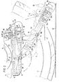
- Fig. 1 shows the rear part of a tractor in side view with the coupling member raised.
- Fig. 2 shows an enlarged view of the lower rear part of the tractor according to Fig. 1 in a side view with the coupling member lowered.
- Fig. 3 shows the middle lower area of the tractor from behind with the coupling member lowered.
- the tractor 2 has a chassis 4 on which a gearbox and bearing housing 6 for a continuous rear wheel axle 8 are attached, at the free ends of which wheels 10, 12 are seated.
- the axis 8 is guided on both sides of the housing 6 through bearing flanges 14.
- a box 16 with a U-shaped cross section and open at the bottom is fastened by means of screws 18.
- two rear links 26 and two front links 28 are articulated on the box on a common pivot axis 22 and 24, respectively.
- the longitudinal legs 30, 32 of a U-beam 34 are articulated, on the transverse legs 36 of which a rear-facing coupling member 38 in the form of a hook open at the top is attached.
- the links 26, 28 are dimensioned in such a way that the U-beam 34 extends from a raised position (FIGS. 1 and 2) in which it extends horizontally under the box 16 on both sides and in which the coupling member 38 is close to the rear 40 of the tractor is in a lowered position (Fig. 2 and 3) can be transferred, in which the U-beam 34 extends obliquely backwards downwards and the coupling member 38 lies on or near the driving surface 42.
- the U-bracket 34 can be raised and lowered in the manner described by means of a lifting and lowering device 46 to be driven by a hydraulic motor 44.
- a releasable locking device 48 is provided for locking the U-beam 34 in the raised position.
- cover 50 for covering the coupling member 38 in the raised position and for securing a mating coupling member coupled to the coupling member 38, for example an eyelet on a pull rod.
- the cover 50 has a recess 51 in the center in its rear lower edge for receiving the nose 39 of the coupling hook 38.
- the lifting and lowering device 46 has lifting and lowering rods 52, 54 articulated on the outer sides of the rear ends of the longitudinal legs 30, 32 of the U-beam 34, the free ends of which via lever linkages 56, 58 having the ends of an output shaft 60 of the hydraulic motor 44 are connected.
- the hydraulic motor 44 thus serves as a lifting and lowering motor. It is screwed onto the top of the housing 6. Every lever linkage consists of a one-armed lever 62 which is articulated via a connecting piece 64 to one of the flanges 14 and at the free end of which one of the lifting and lowering rods 52, 54 is articulated.
- a link 66 is articulated to the central region of each one-armed lever 62.
- the effective length of the handlebar is adjustable by a slot guide 68 for a fixing screw 70, whereby the stroke of the lever linkage 56 or 58 is adjustable.
- the other end of the link 66 is articulated on an arm 72 which sits on the respective end of the output shaft 60.
- the lengths of the lifting and lowering rods 52, 54 are also adjustable.
- a forwardly opening locking hook 74 is articulated above the longitudinal legs 30, 32 of the U-beam 34 to engage under a locking bolt 76 at the rear end of each longitudinal leg 30, 32 of the U-beam 34.
- the two locking hooks 74 sit on the ends of a shaft 78 common to them, which is supported in blocks 80 on the top of the box 16 and is resiliently biased in the locking position of the locking hooks 74 by a helical spring 82 which wraps around them.
- This Bowden cable 88 is supported by a bracket 90 on the rear of the vehicle.
- the core 86 is fastened to an actuating lever 92, which can be operated by the driver on the rear of the tractor 2.
- the locking bolts 76 are provided with side and rear covers 94, 96 which are attached to the U-beam 34.
- the lifting and lowering rods 52, 54 are hinged to sections 98 of the locking bolts 76 which protrude from the side covers 94.
- the U-beam 34 is covered on the underside with a plate 100, so that the U-beam 34 and plate 100 form a box open at the top.
- a support shaft 102 of the coupling hook 38 is fastened to the plate with screws 104.
- a coupling member 106 which is embodied in a different manner and which can be used optionally after the shaft 102 has been released and the shaft 102 has been turned over.
- stop surfaces 108, 110, 112, 114 for limiting the end positions of the U-bracket 34.
- the stop surfaces 108, 110 also ensure that the U Carrier 34 in the lowered position does not come to the handlebars 26 in the dead center position.
Landscapes
- Engineering & Computer Science (AREA)
- Transportation (AREA)
- Mechanical Engineering (AREA)
- Agricultural Machines (AREA)
- Regulating Braking Force (AREA)
- Vehicle Body Suspensions (AREA)
- Control Of Driving Devices And Active Controlling Of Vehicle (AREA)
Abstract
Description
Die Erfindung betrifft eine Vorrichtung zum Ankuppeln eines Anhängers an ein Fahrzeug nach dem Oberbegriff des Anspruchs 1.The invention relates to a device for coupling a trailer to a vehicle according to the preamble of claim 1.
Eine Vorrichtung dieser Art ist nach der DE-A-1455504 bekannt.A device of this type is known from DE-A-1455504.
Nach der EP-A 0184489 ist es bekannt, einen Trägerschaft eines Kupplungshakens,an dessen dem Kupplungshaken abgewandten Ende sich ein in anderer Weise ausgebildetes Kupplungsglied befindet, wahlweise an einem Träger einer Vorrichtung ähnlicher Art zu befestigen, so daß entweder der Kupplungshaken oder das in anderer Weise ausgebildete Kupplungsglied nach hinten vorsteht.According to EP-A 0184489 it is known to attach a carrier shaft of a coupling hook, at the end facing away from the coupling hook, a coupling member of a different design, to a carrier of a device of a similar type, so that either the coupling hook or the other Way trained coupling member protrudes to the rear.
Aufgabe der Erfindung ist es, eine Vorrichtung nach dem Oberbegriff des Anspruchs 1 anzugeben, bei dem ein einfaches Umsetzen eines mit unterschiedlichen Kupplungsgliedern ausgebildetem Trägerschaft bei großer Befestigungssicherheit möglich ist, wobei die Schwenkbewegung des Kupplungsglieds nicht beeinträchtigt wird.The object of the invention is to provide a device according to the preamble of claim 1, in which a simple implementation of a support shaft formed with different coupling members is possible with great fastening reliability, the pivoting movement of the coupling member not being impaired.
Die Lösung dieser Aufgabe ist im Kennzeichen des Anspruchs 1 angegeben.The solution to this problem is specified in the characterizing part of claim 1.
Um das angehobene Kupplungsglied vor Verschmutzung zu bewahren und um ein Lösen zwischen dem Kupplungsglied und der Anhängerkupplung zu vermeiden, ist bevorzugt eine Ausbildung nach Anspruch 2 vorgesehen. Das Anheben und Absenken des Kupplungsglieds wird bei zusätzlicher Führung durch die Ausbildung nach Anspruch 3 erleichtert.In order to protect the raised coupling member from contamination and to avoid loosening between the coupling member and the trailer coupling, an embodiment according to
Zur Anpassung an verschiedene Fahrzeuge ist dabei bevorzugt eine Ausbildung nach Anspruch 4 vorgesehen.To adapt to different vehicles, an embodiment according to claim 4 is preferably provided.
Um das Kupplungsglied in der angehobenen Stellung zu sichern, ist bevorzugt eine Ausbildung nach Ansprauch 5 vorgesehen.In order to secure the coupling member in the raised position, training according to claim 5 is preferably provided.
Um dabei die Verriegelungsbolzen vor Verschmutzung zu bewahren, ist bevorzugt eine Ausbildung nach Anspruch 6 vorgesehen.In order to protect the locking bolts from contamination, an embodiment according to
Eine konstruktive Vereinfachung ergibt sich durch die Ausbildung nach Anspruch 7.A constructive simplification results from the training according to claim 7.
Eine besonders stabile Anordnung erhält man durch die Ausbildung nach Anspruch 8.A particularly stable arrangement is obtained by the training according to
Um das Absenken und Anheben des Kupplungsglieds formschlüssig zu begrenzen, ist bevorzugt eine Ausbildung nach Anspruch 9 vorgesehen.In order to positively limit the lowering and raising of the coupling member, an embodiment according to claim 9 is preferably provided.
Die Erfindung wird im folgenden an einem Ausführungsbeispiel unter Hinweis auf die beigefügten Zeichnungen beschrieben.The invention is described below using an exemplary embodiment with reference to the accompanying drawings.
Fig. 1 zeigt den hinteren Teil eines Traktors in Seitenansicht bei angehobenem Kupplungsglied.Fig. 1 shows the rear part of a tractor in side view with the coupling member raised.
Fig. 2 zeigt vergrößert den unteren hinteren Teil des Traktors nach Fig. 1 in Seitenansicht bei abgesenktem Kupplungsglied.Fig. 2 shows an enlarged view of the lower rear part of the tractor according to Fig. 1 in a side view with the coupling member lowered.
Fig. 3 zeigt den mittleren unteren Bereich des Traktors von hinten bei abgesenktem Kupplungsglied.Fig. 3 shows the middle lower area of the tractor from behind with the coupling member lowered.
Der Traktor 2 nach dem Ausführungsbeispiel weist ein Fahrgestell 4 auf, an dem hinten ein Getriebe- und Lagergehäuse 6 für eine durchgehende Hinterradachse 8 angesetzt sind, an deren freien Enden Räder 10, 12 sitzen. Die Achse 8 ist an beiden Seiten des Gehäuses 6 durch Lagerflansche 14 geführt. An der Unterseite des Gehäuses 6 ist ein im Querschnitt U-förmiger, nach unten offener Kasten 16 mittels Schrauben 18 befestigt. Innerhalb der nach unten weisenden Schenkel 20 des Kastens 16 sind an dem Kasten auf jeweils einer gemeinsamen Schwenkachse 22 bzw. 24 zwei hintere Lenker 26 und zwei vordere Lenker 28 angelenkt. An den freien Enden dieser Lenker 26, 28 sind die Längsschenkel 30, 32 eines U-Trägers 34 angelenkt, an dessen Querschenkel 36 ein nach hinten weisendes Kupplungsglied 38 in Form eines nach oben offenen Hakens angebracht ist. Die Lenker 26, 28 sind derart bemessen, daß der U-Träger 34 aus einerangehobenen Stellung (Fig. 1 und 2), in der er waagerecht unter dem Kasten 16 von dem Kasten 16 beidseitig umschlossen verläuft und in der das Kupplungsglied 38 nahe dem Heck 40 des Traktors liegt, in eine abgesenkte Stellung (Fig. 2 und 3) überführbar ist, in der der U-Träger 34 unter Verlagerung nach rückwärts schräg nach unten hinten verläuft und das Kupplungsglied 38 auf oder nahe der Fahrfläche 42 liegt.The
Der U-Träger 34 ist mittels einer von einem Hydraulikmotor 44 anzutreibenden Hub- und Senkvorrichtung 46 in der beschriebenen Weise anzuheben und abzusenken. Zum Verriegeln des U-Trägers 34 in der angehobenen Stellung ist eine lösbare Verriegelungsvorrichtung 48 vorgesehen.The U-bracket 34 can be raised and lowered in the manner described by means of a lifting and lowering
Am Heck 40 ist eine Abdeckung 50 (keeper-plate) zum Abdecken des Kupplungsglieds 38 in der angehobenen Stellung und zum Sichern eines mit dem Kupplungsglied 38 gekuppelten Gegenkupplungsglieds, beispielsweise einer Öse an einer Zugstange, angebracht. Die Abdeckung 50 weist in ihrer hinteren Unterkante mittig eine Ausnehmung 51 zur Aufnahme der Nase 39 des Kupplungshakens 38 auf.At the rear 40 there is a cover 50 (keeper plate) for covering the
Die Hub- und Senkvorrichtung 46 weist an den Außenseiten der hinteren Enden der Längsschenkel 30, 32 des U-Trägers 34 angelenkte Hub- und Senkstangen 52, 54 auf, deren freie Enden über Hebelgestänge 56, 58 mit den Enden einer Ausgangswelle 60 des Hydraulikmotors 44 verbunden sind. Der Hydraulikmotor 44 dient somit als Hub- und Senkmotor. Er ist auf der Oberseite des Gehäuses 6 angeschraubt. Jedes Hebelgestänge besteht aus einem einarmigen Hebel 62, der über ein Verbindungsstück 64 an einem der Flansche 14 angelenkt ist und an dessen freies Ende eine der Hub- und Senkstangen 52, 54 angelenkt ist. An den Mittelbereich jedes einarmigen Hebels 62 ist ein Lenker 66 angelenkt. Die effektive Länge des Lenkers ist durch eine Schlitzführung 68 für eine Festsetzschraube 70 verstellbar, wodurch der Hub des Hebelgestänges 56 bzw. 58 einstellbar ist. Das andere Ende des Lenkers 66 ist an einem Arm 72 angelenkt, der auf dem jeweiligen Ende der Ausgangswelle 60 sitzt. Auch die Längen der Hub- und Senkstangen 52, 54 sind verstellbar. Am Heck 40 des Traktors 2 ist über den Längsschenkeln 30, 32 des U-Trägers 34 jeweils ein nach vorne offener Verriegelungshaken 74 zum Untergreifen eines Verriegelungsbolzens 76 am hinteren Ende jedes Längsschenkels 30, 32 des U-Trägers 34 angelenkt. Die beiden Verriegelungshaken 74 sitzen auf den Enden einer ihnen gemeinsamen Welle 78, die in Böcken 80 auf der Oberseite des Kastens 16 gelagert ist und durch eine sie umschlingende Schraubenfeder 82 in Verriegelungsstellung der Verriegelungshaken 74 federnd vorgespannt ist. An der Welle 78 sitzt ein Arm 84, an den die Seele 86 eines Bowdenzugs 88 angreift. Dieser Bowdenzug 88 ist durch einen Bügel 90 am Fahrzeugheck abgestützt. Die Seele 86 ist an einem Betätigungshebel 92 befestigt, der vom Fahrer bedienbar hinten am Traktor 2 angelenkt ist. Die Verriegelungsbolzen 76 sind mit seitlichen und hinteren Abdeckungen 94, 96 versehen, die am U-Träger 34 angebracht sind.The lifting and lowering
Die Hub- und Senkstangen 52, 54 sind an aus den seitlichen Abdeckungen 94 herausragenden Abschnitten 98 der Verriegelungsbolzen 76 angelenkt.The lifting and lowering
Der U-Träger 34 ist unterseitig mit einer Platte 100 abgedeckt, so daß U-Träger 34 und Platte 100 einen nach oben offenen Kasten bilden. Auf der Platte ist ein Trägerschaft 102 des Kupplungshakens 38 mit Schrauben 104 befestigt. An dem den Kupplungshaken 38 abgewandten Ende des Schafts 102 befindet sich ein in anderer Weise ausgebildetes Kupplungsglied 106, das wahlweise nach Lösen des Schafts 102 und Umdrehen des Schafts 102 benutzt werden kann.The U-beam 34 is covered on the underside with a
An den Lenkern 26, 28, an dem U-Träger 34 und an dem Kasten 16 befinden sich Anschlagflächen 108, 110, 112, 114 zur Begrenzung der Endlagen des U-Trägers 34. Die Anschlagflächen 108, 110 sorgen überdies dafür, daß der U-Träger 34 in der abgesenkten Stellung nicht in Übertotpunktlage zu den Lenkern 26 gerät.On the
Claims (7)
- A device for coupling a trailer to a vehicle (2), in particular a tractor, having front links (26), which are articulated symmetrically to the vehicle centre line below the tail region of the vehicle (2), and rear links (28), the free ends of said links are connected in an articulated manner to a plurality of longitudonal parallel arms (30, 32) of a U-shaped support member (34) which is formed by said longitudonal arms (30, 32) and a transverse arm (36), said U-shaped support member (33) containing the transverse arm (36) at its tail region, where a rearwardly facing coupling member (38) is mounted, wherein the links (26, 28) are of such dimensions that the U-shaped support member (34) can be transferred from a raised position, in which it extends horizontally below the tail region of the vehicle (2) and the coupling member (38) is situated near to the tail region, into a lowered position, in which the U-shaped support member (34) extends obliquely downwards and rearwards, having been shifted rearwards, and the coupling member (38) is situated on or near the road surface (42), a raising and lowering device (46) being provided for the U-shaped support member (34) and a releasable locking device (48) being provided for locking the U-shaped support member (34) in the raised position, characterised in that on its underside the U-shaped support member (34) is covered by a plate (100) so that the U-shaped support member (34) and the plate (100) form an upwardly open box, and in theat a carrier shaft (102) of the coupling hook (38) is releasanly mounted by means of screws(104) on the plate (100), a coupling member (106) of different design being disposed at the end of said carrier shaft remote from the coupling hook (38), and that abutment faces (108, 110, 112, 114) for limiting the end positions of the U-shaped support member (34) are provided on the links (26, 28), the U-shaped support member (34) and the underside of the tail region.
- A device according to Claim 1 characterised in that a keeper-plate (50) is mounted in the tail region for covering the coupling member (38) in the raised position and for securing a countercoupling member coupled to the coupling member (38).
- A device according to Claim 1 or 2, characterised in that raising and lowering bars (52, 54) are articulated to the outsides of the rear ends of the longitudinal arms (30, 32) of the U-shaped support member (34), the free ends of which bars (52, 54) are connected via lever bars (56, 58) to the ends of an output shaft (6) of a hydraulic raising and lowering motor (44) mounted in the tail region of the vehicle (2).
- A device according to Claim 3, characterised in that the travel of the lever bars (56, 58) is designed to be adjustable.
- A device according to any one of the preceding Claims, characterised in that in the tail region, above the longitudinal arms (30, 32) of the U-shaped support member (34), forwardly open locking hooks (74) for engaging under locking pins (76) are articulated to the rear ends of the longitudinal arms (30, 32) of the U-shaped support member (34), and in that these locking hooks (74) are elastically preloaded in the locking position and can be pivoted out of their locking position by a Bowden cable (88) which can be actuated from the vehicle (2).
- A device according to Claim 5, characterised in that the locking pins (76) are provided with lateral covers (94) and rear covers (96).
- A device according to Claims 3 and 6, characterised in that the raising and lowering bars (52, 54) are articulated to portions (98) of the locking pins (76) projecting from the lateral covers (94).
Priority Applications (1)
| Application Number | Priority Date | Filing Date | Title |
|---|---|---|---|
| AT89110825T ATE74075T1 (en) | 1988-06-16 | 1989-06-14 | DEVICE FOR HITCHING A TRAILER TO A VEHICLE. |
Applications Claiming Priority (2)
| Application Number | Priority Date | Filing Date | Title |
|---|---|---|---|
| DE8807849U | 1988-06-16 | ||
| DE8807849U DE8807849U1 (en) | 1988-06-16 | 1988-06-16 | Device for coupling a trailer to a vehicle |
Publications (3)
| Publication Number | Publication Date |
|---|---|
| EP0346885A1 EP0346885A1 (en) | 1989-12-20 |
| EP0346885B1 EP0346885B1 (en) | 1992-03-25 |
| EP0346885B2 true EP0346885B2 (en) | 1995-01-18 |
Family
ID=6825118
Family Applications (1)
| Application Number | Title | Priority Date | Filing Date |
|---|---|---|---|
| EP89110825A Expired - Lifetime EP0346885B2 (en) | 1988-06-16 | 1989-06-14 | Apparatus for attaching a trailer to a vehicle |
Country Status (4)
| Country | Link |
|---|---|
| EP (1) | EP0346885B2 (en) |
| AT (1) | ATE74075T1 (en) |
| DE (2) | DE8807849U1 (en) |
| ES (1) | ES2031312T3 (en) |
Cited By (1)
| Publication number | Priority date | Publication date | Assignee | Title |
|---|---|---|---|---|
| DE202008014513U1 (en) | 2008-10-31 | 2009-01-22 | Sauermann, Hans | Trailer coupling for a vehicle, in particular for a farm tractor |
Families Citing this family (6)
| Publication number | Priority date | Publication date | Assignee | Title |
|---|---|---|---|---|
| DE4120119A1 (en) * | 1991-06-19 | 1992-12-24 | Walterscheid Gmbh Jean | DEVICE FOR ATTACHING A TRAILER OR ATTACHMENT TO A TRACTOR |
| DE4427399A1 (en) * | 1994-08-03 | 1996-02-15 | Deere & Co | Tractor towing-hitch |
| DE19953833A1 (en) * | 1999-11-09 | 2001-05-10 | Hans Sauermann | Coupling device for a motor vehicle |
| DE102004029577A1 (en) * | 2004-06-18 | 2005-12-29 | Deere & Company, Moline | Telescopic power transmission device |
| FI120870B (en) * | 2006-05-16 | 2010-04-15 | Lh Lift Oy | Tow hitch arrangement and method for coupling an object to be towed to a working machine |
| DE202012008848U1 (en) | 2012-09-17 | 2013-12-18 | Hans Sauermann | Coupling device for a motor vehicle |
Family Cites Families (5)
| Publication number | Priority date | Publication date | Assignee | Title |
|---|---|---|---|---|
| US2725243A (en) * | 1953-05-18 | 1955-11-29 | William P Paulsen | Lifting drawbar for tractors |
| US2926931A (en) * | 1957-09-02 | 1960-03-01 | Ford Motor Co | Automatic trailer hitches |
| DE1455504C3 (en) * | 1964-08-01 | 1974-11-21 | Kloeckner-Humboldt-Deutz Ag, 5000 Koeln | Coupling device for hitching a vehicle to a towing vehicle equipped with a power lift |
| GB8326995D0 (en) * | 1983-10-08 | 1983-11-09 | Agricultural Requisites & Mech | Towing hitches |
| FR2573360B1 (en) * | 1984-11-16 | 1987-01-09 | Lemoine Mecano Soudure | MOBILE SLEEVE HITCH |
-
1988
- 1988-06-16 DE DE8807849U patent/DE8807849U1/en not_active Expired
-
1989
- 1989-06-14 ES ES198989110825T patent/ES2031312T3/en not_active Expired - Lifetime
- 1989-06-14 DE DE8989110825T patent/DE58901018D1/en not_active Expired - Lifetime
- 1989-06-14 EP EP89110825A patent/EP0346885B2/en not_active Expired - Lifetime
- 1989-06-14 AT AT89110825T patent/ATE74075T1/en not_active IP Right Cessation
Cited By (1)
| Publication number | Priority date | Publication date | Assignee | Title |
|---|---|---|---|---|
| DE202008014513U1 (en) | 2008-10-31 | 2009-01-22 | Sauermann, Hans | Trailer coupling for a vehicle, in particular for a farm tractor |
Also Published As
| Publication number | Publication date |
|---|---|
| DE8807849U1 (en) | 1988-08-25 |
| EP0346885A1 (en) | 1989-12-20 |
| ATE74075T1 (en) | 1992-04-15 |
| ES2031312T3 (en) | 1992-12-01 |
| DE58901018D1 (en) | 1992-04-30 |
| EP0346885B1 (en) | 1992-03-25 |
Similar Documents
| Publication | Publication Date | Title |
|---|---|---|
| DE69018085T2 (en) | RETRACTABLE SUSPENSION. | |
| DE3877031T2 (en) | TRAINING THE REAR UNDERFLOOR OF A MOTOR VEHICLE. | |
| DE69202473T2 (en) | Drawbar for trailers. | |
| EP0324974A1 (en) | Device for the frontal mounting of equipment on a small tractor, especially a garden or lawn tractor | |
| EP0346885B1 (en) | Apparatus for attaching a trailer to a vehicle | |
| DE10031024B4 (en) | Combination transport train for the transport of long or short material | |
| DE3030279C2 (en) | articulated lorry | |
| DE2354776C2 (en) | ||
| DE2651936A1 (en) | Lifting control for single axle trailer - has hydraulic servo in flat location in plane of tow bar | |
| EP0544268B1 (en) | Support of the coupler jaw of the locking bar of a fifth-wheel coupling | |
| DE1780503C3 (en) | Suspension for semi-trailers | |
| DE8807614U1 (en) | Haymaking machine | |
| EP0827848B1 (en) | Chassis for motor vehicles or trailers | |
| DE3801895A1 (en) | Device on the front end of a farm tractor for raising an additional weight carrier into a transportation position | |
| EP0133637A1 (en) | Front implement hitch device for a front covered vehicle for use in agriculture and/or the building industry, in particular for a farming tractor | |
| DE69402758T2 (en) | DEVICE FOR A ROAD TRANSPORT VEHICLE OR A MANEUVER VEHICLE AND VEHICLE WITH SUCH A DEVICE | |
| DE69800392T2 (en) | Wheel suspension for a vehicle | |
| DE4239528C2 (en) | Coupling device | |
| DE69718848T2 (en) | Trailer construction | |
| EP0231555A1 (en) | Coupling device between a truck and a trailer | |
| AT244164B (en) | Auxiliary chassis for the road transport of an all-terrain caterpillar vehicle | |
| EP0381926A2 (en) | Trailer hitch for agricultural vehicles, especially trailers | |
| DE1555199C (en) | Coupling device, in particular for connecting a trailer to a towing vehicle | |
| DE3109925A1 (en) | TOW ROD TRAILER | |
| DE402690C (en) | Spring arrangement for a tractor in which the carriage frame is resiliently suspended from only one drive wheel |
Legal Events
| Date | Code | Title | Description |
|---|---|---|---|
| PUAI | Public reference made under article 153(3) epc to a published international application that has entered the european phase |
Free format text: ORIGINAL CODE: 0009012 |
|
| AK | Designated contracting states |
Kind code of ref document: A1 Designated state(s): AT BE CH DE ES FR GB GR IT LI LU NL SE |
|
| 17P | Request for examination filed |
Effective date: 19900109 |
|
| 17Q | First examination report despatched |
Effective date: 19910110 |
|
| GRAA | (expected) grant |
Free format text: ORIGINAL CODE: 0009210 |
|
| AK | Designated contracting states |
Kind code of ref document: B1 Designated state(s): AT BE CH DE ES FR GB GR IT LI LU NL SE |
|
| PG25 | Lapsed in a contracting state [announced via postgrant information from national office to epo] |
Ref country code: GR Free format text: LAPSE BECAUSE OF FAILURE TO SUBMIT A TRANSLATION OF THE DESCRIPTION OR TO PAY THE FEE WITHIN THE PRESCRIBED TIME-LIMIT Effective date: 19920325 |
|
| REF | Corresponds to: |
Ref document number: 74075 Country of ref document: AT Date of ref document: 19920415 Kind code of ref document: T |
|
| ITF | It: translation for a ep patent filed | ||
| REF | Corresponds to: |
Ref document number: 58901018 Country of ref document: DE Date of ref document: 19920430 |
|
| PGFP | Annual fee paid to national office [announced via postgrant information from national office to epo] |
Ref country code: ES Payment date: 19920619 Year of fee payment: 4 |
|
| PGFP | Annual fee paid to national office [announced via postgrant information from national office to epo] |
Ref country code: BE Payment date: 19920624 Year of fee payment: 4 |
|
| PGFP | Annual fee paid to national office [announced via postgrant information from national office to epo] |
Ref country code: LU Payment date: 19920630 Year of fee payment: 4 |
|
| ET | Fr: translation filed | ||
| GBT | Gb: translation of ep patent filed (gb section 77(6)(a)/1977) | ||
| EPTA | Lu: last paid annual fee | ||
| REG | Reference to a national code |
Ref country code: ES Ref legal event code: FG2A Ref document number: 2031312 Country of ref document: ES Kind code of ref document: T3 |
|
| PLBI | Opposition filed |
Free format text: ORIGINAL CODE: 0009260 |
|
| 26 | Opposition filed |
Opponent name: ROCKINGER SPEZIALFABRIK FUER ANHAENGERKUPPLUNGEN G Effective date: 19921222 |
|
| NLR1 | Nl: opposition has been filed with the epo |
Opponent name: ROCKINGER SPEZIALFABRIK FUER ANHAENGERKUPPLUNGEN G |
|
| PG25 | Lapsed in a contracting state [announced via postgrant information from national office to epo] |
Ref country code: LU Free format text: LAPSE BECAUSE OF NON-PAYMENT OF DUE FEES Effective date: 19930614 |
|
| PG25 | Lapsed in a contracting state [announced via postgrant information from national office to epo] |
Ref country code: ES Free format text: LAPSE BECAUSE OF THE APPLICANT RENOUNCES Effective date: 19930615 |
|
| PG25 | Lapsed in a contracting state [announced via postgrant information from national office to epo] |
Ref country code: BE Effective date: 19930630 |
|
| BERE | Be: lapsed |
Owner name: SAUERMANN ROMAN JOHANN Effective date: 19930630 |
|
| PLAB | Opposition data, opponent's data or that of the opponent's representative modified |
Free format text: ORIGINAL CODE: 0009299OPPO |
|
| R26 | Opposition filed (corrected) |
Opponent name: ROCKINGER SPEZIALFABRIK FUER ANHAENGERKUPPLUNGEN G Effective date: 19921222 |
|
| PUAH | Patent maintained in amended form |
Free format text: ORIGINAL CODE: 0009272 |
|
| STAA | Information on the status of an ep patent application or granted ep patent |
Free format text: STATUS: PATENT MAINTAINED AS AMENDED |
|
| 27A | Patent maintained in amended form |
Effective date: 19950118 |
|
| AK | Designated contracting states |
Kind code of ref document: B2 Designated state(s): AT BE CH DE ES FR GB GR IT LI LU NL SE |
|
| EAL | Se: european patent in force in sweden |
Ref document number: 89110825.0 |
|
| REG | Reference to a national code |
Ref country code: CH Ref legal event code: AEN |
|
| NLR2 | Nl: decision of opposition | ||
| ITF | It: translation for a ep patent filed | ||
| GBTA | Gb: translation of amended ep patent filed (gb section 77(6)(b)/1977) |
Effective date: 19950329 |
|
| ET3 | Fr: translation filed ** decision concerning opposition | ||
| NLR3 | Nl: receipt of modified translations in the netherlands language after an opposition procedure | ||
| REG | Reference to a national code |
Ref country code: ES Ref legal event code: FD2A Effective date: 19991007 |
|
| REG | Reference to a national code |
Ref country code: GB Ref legal event code: IF02 |
|
| PGFP | Annual fee paid to national office [announced via postgrant information from national office to epo] |
Ref country code: CH Payment date: 20070531 Year of fee payment: 19 |
|
| PGFP | Annual fee paid to national office [announced via postgrant information from national office to epo] |
Ref country code: SE Payment date: 20070607 Year of fee payment: 19 |
|
| PGFP | Annual fee paid to national office [announced via postgrant information from national office to epo] |
Ref country code: NL Payment date: 20070629 Year of fee payment: 19 |
|
| PGFP | Annual fee paid to national office [announced via postgrant information from national office to epo] |
Ref country code: AT Payment date: 20070630 Year of fee payment: 19 |
|
| PGFP | Annual fee paid to national office [announced via postgrant information from national office to epo] |
Ref country code: DE Payment date: 20070822 Year of fee payment: 19 |
|
| REG | Reference to a national code |
Ref country code: CH Ref legal event code: PFA Owner name: ROMAN JOHANN SAUERMANN Free format text: ROMAN JOHANN SAUERMANN#HOHENWARTER STRASSE 29#FREINHAUSEN (DE) -TRANSFER TO- ROMAN JOHANN SAUERMANN#HOHENWARTER STRASSE 29#FREINHAUSEN (DE) |
|
| PGFP | Annual fee paid to national office [announced via postgrant information from national office to epo] |
Ref country code: GB Payment date: 20070531 Year of fee payment: 19 |
|
| PGFP | Annual fee paid to national office [announced via postgrant information from national office to epo] |
Ref country code: IT Payment date: 20070627 Year of fee payment: 19 |
|
| PGFP | Annual fee paid to national office [announced via postgrant information from national office to epo] |
Ref country code: FR Payment date: 20070531 Year of fee payment: 19 |
|
| REG | Reference to a national code |
Ref country code: CH Ref legal event code: PL |
|
| EUG | Se: european patent has lapsed | ||
| GBPC | Gb: european patent ceased through non-payment of renewal fee |
Effective date: 20080614 |
|
| NLV4 | Nl: lapsed or anulled due to non-payment of the annual fee |
Effective date: 20090101 |
|
| REG | Reference to a national code |
Ref country code: FR Ref legal event code: ST Effective date: 20090228 |
|
| PG25 | Lapsed in a contracting state [announced via postgrant information from national office to epo] |
Ref country code: AT Free format text: LAPSE BECAUSE OF NON-PAYMENT OF DUE FEES Effective date: 20080614 Ref country code: DE Free format text: LAPSE BECAUSE OF NON-PAYMENT OF DUE FEES Effective date: 20090101 |
|
| PG25 | Lapsed in a contracting state [announced via postgrant information from national office to epo] |
Ref country code: NL Free format text: LAPSE BECAUSE OF NON-PAYMENT OF DUE FEES Effective date: 20090101 |
|
| PG25 | Lapsed in a contracting state [announced via postgrant information from national office to epo] |
Ref country code: CH Free format text: LAPSE BECAUSE OF NON-PAYMENT OF DUE FEES Effective date: 20080630 Ref country code: GB Free format text: LAPSE BECAUSE OF NON-PAYMENT OF DUE FEES Effective date: 20080614 Ref country code: LI Free format text: LAPSE BECAUSE OF NON-PAYMENT OF DUE FEES Effective date: 20080630 |
|
| PG25 | Lapsed in a contracting state [announced via postgrant information from national office to epo] |
Ref country code: IT Free format text: LAPSE BECAUSE OF NON-PAYMENT OF DUE FEES Effective date: 20080614 Ref country code: FR Free format text: LAPSE BECAUSE OF NON-PAYMENT OF DUE FEES Effective date: 20080630 |
|
| PG25 | Lapsed in a contracting state [announced via postgrant information from national office to epo] |
Ref country code: SE Free format text: LAPSE BECAUSE OF NON-PAYMENT OF DUE FEES Effective date: 20080615 |