EP0346537A1 - Méthode de correction de la trajectoire d'un véhicule autonome sans conducteur (véhicule robot) - Google Patents
Méthode de correction de la trajectoire d'un véhicule autonome sans conducteur (véhicule robot) Download PDFInfo
- Publication number
- EP0346537A1 EP0346537A1 EP88305421A EP88305421A EP0346537A1 EP 0346537 A1 EP0346537 A1 EP 0346537A1 EP 88305421 A EP88305421 A EP 88305421A EP 88305421 A EP88305421 A EP 88305421A EP 0346537 A1 EP0346537 A1 EP 0346537A1
- Authority
- EP
- European Patent Office
- Prior art keywords
- path
- given
- travel
- unmanned vehicle
- distance
- Prior art date
- Legal status (The legal status is an assumption and is not a legal conclusion. Google has not performed a legal analysis and makes no representation as to the accuracy of the status listed.)
- Withdrawn
Links
- 238000000034 method Methods 0.000 title claims abstract description 40
- 238000012937 correction Methods 0.000 claims description 39
- 238000013459 approach Methods 0.000 description 4
- 238000005259 measurement Methods 0.000 description 4
- 230000008859 change Effects 0.000 description 3
- 238000004891 communication Methods 0.000 description 3
- 230000006870 function Effects 0.000 description 3
- 230000007246 mechanism Effects 0.000 description 3
- 238000011161 development Methods 0.000 description 2
- 238000002604 ultrasonography Methods 0.000 description 2
- 230000001133 acceleration Effects 0.000 description 1
- 230000009471 action Effects 0.000 description 1
- 230000004069 differentiation Effects 0.000 description 1
Images


Classifications
-
- G—PHYSICS
- G05—CONTROLLING; REGULATING
- G05D—SYSTEMS FOR CONTROLLING OR REGULATING NON-ELECTRIC VARIABLES
- G05D1/00—Control of position, course, altitude or attitude of land, water, air or space vehicles, e.g. using automatic pilots
- G05D1/02—Control of position or course in two dimensions
- G05D1/021—Control of position or course in two dimensions specially adapted to land vehicles
- G05D1/0255—Control of position or course in two dimensions specially adapted to land vehicles using acoustic signals, e.g. ultra-sonic singals
-
- G—PHYSICS
- G05—CONTROLLING; REGULATING
- G05D—SYSTEMS FOR CONTROLLING OR REGULATING NON-ELECTRIC VARIABLES
- G05D1/00—Control of position, course, altitude or attitude of land, water, air or space vehicles, e.g. using automatic pilots
- G05D1/02—Control of position or course in two dimensions
- G05D1/021—Control of position or course in two dimensions specially adapted to land vehicles
- G05D1/0268—Control of position or course in two dimensions specially adapted to land vehicles using internal positioning means
- G05D1/0272—Control of position or course in two dimensions specially adapted to land vehicles using internal positioning means comprising means for registering the travel distance, e.g. revolutions of wheels
-
- G—PHYSICS
- G05—CONTROLLING; REGULATING
- G05D—SYSTEMS FOR CONTROLLING OR REGULATING NON-ELECTRIC VARIABLES
- G05D1/00—Control of position, course, altitude or attitude of land, water, air or space vehicles, e.g. using automatic pilots
- G05D1/02—Control of position or course in two dimensions
- G05D1/021—Control of position or course in two dimensions specially adapted to land vehicles
- G05D1/0268—Control of position or course in two dimensions specially adapted to land vehicles using internal positioning means
- G05D1/0274—Control of position or course in two dimensions specially adapted to land vehicles using internal positioning means using mapping information stored in a memory device
Definitions
- the present invention relates to an unmanned vehicle which, upon specification of the target location (destination) will search its travel path to the target location (destination) on the basis of previously given geographic data and travel to said target location (destination) while recognizing its own currently traversed path, and to a path correction method whereby the travel path will be corrected, notably in the event that said self-contained unmanned vehicle deviates from its normal travel path.
- unmanned vehicles or robot cars capable of automatyically conveying items or objects such as parts and components within premises such as factory and warehouse precincts.
- the development of such robot cars includes a category known as self-contained unmanned vehicles, which, by merely specifying the node or nodal point corresponding to the target location or destination, are capable of independently searching for the optimum travel path and of determining the nodes to be traversed to reach said destination node, thereby ensuring automatic travel motion to the destination node.
- node denotes any location or point in which a change in the unmanned vehicle's travel condition such as its travel speed and/or its direction of movement occurs as is the case in stop locations, turn-off points, and operating/handling positions.
- Fig. 6 is an arrangement plan showing the general configuration of this type of self-contained unmanned vehicle.
- items 2L and 2R represent the left and right drive wheels, respectively, 3L and 3R the motors driving the left and right drive wheels 2L and 2R, respectively, 4L and 4R the pulse encoders for detecting the rotational speeds of the left and right wheels 2L and 3R, respectively, 5,5 ... castor-type roller-wheels, 6L and 6R ultrasound receiving units for sensing the distance from the unmanned vehicle to the left and right walls, respectively, and 7 the control unit.
- Said control unit 7 consists of a microprocessor memory which holds previously stored geographic data relating to the travel path. Said geographic data relate to the co-ordinates of all nodes traversed by the unmanned vehicles in its approach towards the destination point and to the distances from the unmanned vehicle to the left and right sides with respect to a given pre-determined travel path passing through these nodes.
- this target node instruction is supplied through a communication unit, which is not shown in the figure, to the control unit 7, whereupon said control unit 7 will search for the optimum travel path on the basis of the geographic data and determine the node or nodes to be traversed by said unmanned vehicle on its approach to the given destination node so as to set the motors 3L and 3R, respectively, in motion to ensure the unmanned vehicle's travel along the pre-determined travel path linking, in consecutive sequence, the respective nodes. Said control unit 7 will then measure the distance to the left and right side walls W on the basis of the signals supplies from the ultrasonic transmitter/receiver devices 6L and 6R, respectively.
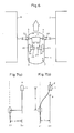
- Fig. 7a when the amount of off-set D is larger than a given value, the unmanned vehicle 1 is caused to stop momentarily.
- the attitude of the drive wheels 2L and 3R is then inverted by an angle of 90°, whereupon the unmanned vehicle 1 will move sideways to the right, thereby performing an action known as a side-step movement to advance as far as the pre-determined normal travel path l0, when the unmanned vehicle 1 will again stop. Travel will then be resumed after the drive wheels 2L and 2R, respectively, have subsequently been re-aligned to the normal travel direction.
- the forward path of the unmanned vehicle 1 will be modified only by a given angle in the right-hand direction by controlling the wheel speed difference between the drive wheels 2L and 2R, respectively, whereupon said unmanned vehicle 1 will traverse, in a rectilinear movement, a suitable distance such that the forward path of said unmanned vehicle 1 is re-directed to the left by a given angle, thereby re-establishing the pre-determined normal travel path l0 by causing the unmanned vehicle 1 to described a given pattern of curvilinear motion while continuing to maintain its forward travel movement.
- the object of the present invention is to provide a means to restore an unmanned vehicle on its aforesaid pre-determined normal travel path in front of the normal node by minimizing the power consumption and travel time losses even when said unmanned vehicle has deviated from its predetermined normal travel path.
- the present invention uses a travel path correction method in which: at the moment in which the present travel path deviates, by a given amount, from the predetermined normal travel path, the given distance required for correcting the path, through a combination of curves given from the current position, is compared with the remaining travel distance until the node reached next from the current position, in such a manner that, if the remaining distance is greater than the given required distance, the travel path will be corrected by a combination of a given pattern of curves on the assumption that the path correction procedure will be completed ahead of the node reached next.
- the travel path will be corrected by a side-step movement in which the attitude of the drive wheel is re-directed so as to provide for a movement towards the side, on the assumption that the path correction procedure will be completed ahead of the node reached next.
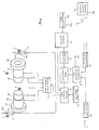
- Fig. 1 is a block schematic showing the configuration of a self-contained unmanned vehicle in which the path correction method according to a preferred embodiment of the present invention is applied.
- item 10 is a distance-measuring element for determining the travel distance from the node traversed immediately beforehand by calculation on the basis of the pulse signals LP and RP supplied from the pulse encoders 4L and 4R. It also determines the distance from the unmanned vehicle to the left and right side walls by calculation on the basis of the signals supplied from-the ultrasound transmitter/receiver units 6L and 6R, respectively.
- Item 11 is a geographic data memory in which the geographic data have been previously stored.
- Item 12 is a data comparator for comparing the distance-measurement data output from the distance-measuring element 10 with the geographic data output from the geographic data memory 11.
- item 20 is a control section which operates in such a manner that when the destination node specified through wireless communication from the central control station 23 is supplied through the communication unit 24, it searches for the optimum path on the basis of the geographic data, then determines the node or nodes to be traversed on the approach route to the destination node, generates the necessary travel commands to ensure travel motion along the predetermined path interlinking these nodes, and transmits these commands to the travel control section 13.
- Said travel control section 13 generates the speed control signals for controlling the rotational speed of the left and right drive motors 2L and 2R, respectively, on the basis of the travel commands supplied from the control section 20, and supplies these speed control signals to the drive wheel control unit 14.
- said travel control section 13 makes a judgment, on the basis of the comparison data supplied from the data comparator 12, to establish whether or not the current travel path deviates, to an extent greater than a given amount d, from the pre-determined normal travel path obtained on the basis of the geographic data, and if it does, the corresponding speed control signals are supplied to the drive wheel control section 14, or, if necessary, the brake system is activated to correct the path by the procedure described hereinafter.
- the drive wheel control unit 14 controls the rotational speed of the motors 3L and 3R, respectively, on the bsis of the speed control signals supplied from the travel control unit 13 and the speed feedback signals supplied from the pulse encoders 4L and 4R, respectively.
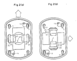
- the brake mechanism 15 consists of a braking cylinder, with one such brake mechanism being provided in the vicinity of each of the two idler wheels 5 and 5, respectively, at the front and back and located mutually diagonally on the floor of the unmanned vehicle, as shown in Fig. 2.
- the rod 15a of the electric power cylinder projects in the bottom direction so that the rubber element 15b mounted on the tip of this rod 15a strikes the bedplate on its descent, thereby actuating the brake.
- the left and right wheels 2L and 2R are caused to rotate in the reverse sense so that said left and right drive wheels 2L and 2R will change their attitude from the normal direction shown in Fig. 2a to a direction obtained by turning said wheels through an angle of 90°, with point R as the center of rotation.
- item 21 is the memory in which are previously stored the path correction curve data, which data are consulted, i.e., referred to, by the travel control unit 13 when correcting the travel path by way of a combination of a given pattern of curves.
- the following types of curve data are stored in this memory.
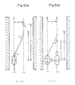
- the first type of curve data are the control data used for altering the unmanned vehicle's travel direction only by a given angle in the right-hand direction so as to cause the unmanned vehicle to described a given pattern of curves.
- the second type of curve data are the control data for altering the unmanned vehicle's travel direction only by as given angle in the left-hand direction so as to cause the unmanned vehicle to describe a givven pattern of curves.
- the first curve data referred to above are essential control data required for controlling the unmanned vehicle in such a manner that while said unmanned vehicle advances from the bottom of Fig. 3 to the top, it is made to described a curve C1, given in the same figure.
- the direction of movement of the unmanned vehicle is caused to alter only by a given angle in the right-hand direction.
- the unmanned vehicle moves only by half the given distance d (d/2) toward the right in the figure.
- the second curve data referred to above are essential control data required for controlling the unmanned vehicle in such a manner that it is made to describe curve C2 oriented in a direction opposite to that of the first curve data. Consequently, as a result of its movement along curve C2, the direction of movement of the unmanned vehicle is caused to alter only by the given angle in the left-hand direction. During this, the unmanned vehicle moves only by half the distance d (d/2) towards the left in the figure.
- the travel control unit 13 is provided with a control function such that it can control the unmanned vehicle so as to maintain its present travel condition without changing its direction of forward movement and without changing its speed, that is, a control function causing the unmanned vehicle to travel at an uniform speed on a rectilinear path.
- the travel control unit 13 is furnished with a decision-making function so that it can execute a selection between the correction mode in which the correction of the travel path of the unmanned vehicle is achieved by a combination of a given pattern of curves in accordance with the distance from the unmanned vehicle to the node to be reached next and the correction mode in which the correction of the travel path of the unmanned vehicle is achieved by means of a side-step movement.
- the given distance L required for correcting the travel path from the present position by means of a combination of a given pattern of curves and the remaining travel distance L1 from the present position to the node to be traversed next are compared, and if the remaining distance L1 is greater than the given distance L, the travel path is corrected by means of said combination of curves of a given pattern, whereas, if the remaining distance L1 is smaller than the distance 11, the travel path is corrected by the side-step method in which the left and right drive wheels 2L and 2R are shifted sideways through an angle of 90d.
- the unmanned vehicle compares, during its travel, the distance-measurement data and the geographic data (Step SP1), and determines the off-set amount D, being the difference between said distance-measurement data and said geographic data.
- Step SP2 the amount of off-set D and the given value d are compared. If the given value d is equal to the sum obtained from the distance d/2, being the distance by which the unmanned vehicle advances in the right direction as shown in Fig. 3, curve C1 will be used, and, conversely, if the distance value is equal to the distance d/2, being the distance by which the unmanned vehicle advances in the left dirction as shown in Fig. 3, curve C2 is used.
- the unmanned vehicle now travels along a travel path tht is significantly offset from the pre-determined normal path l0 towards the left in the figure, and if, therefore, the amount of offset is in excess of the given value d, then the next step SP3 will be engaged.
- the control section 13 compares the given distance L required for completing the correction of the travel path from the present position on the travel path 11 by means of a combination of curves of a given pattern and the remaining travel distance L1 from the present position to the node N to be traversed next.
- step SP3 has made the judgment that the remaining travel distance L1 > given distance so that the path correction is considered as being completed ahead of the node N to be reached next and the procedure goes over to step SP4.
- the procedures given next for steps SP4 ---> SP6 the travel path is corrected by a combination of curves of a given pattern.
- step SP4 the travel control section 13 controls the travel path of the unmanned vehicle on the basis of the first curve data stored in memory 21, causing the unmanned vehicle to follow curve C1.
- the unmanned vehicle continues its travel motion, and the direction of this travel motion changes from the travel path l1 towards the right only by the given angle ⁇ , advancing from the travel path l1 towards the right only by the distance d/2 (step SP4).
- step SP5 is initiated by causing the unmanned vehicle to travel at a uniform speed in rectilinear motion. As can be seen from Fig.
- the travel distance in this case is equal to the distance resulting when the unmanned vehicle is displaced to the right by a distance (D-d) obtained by subtracting the given value d from the off-set amount D.
- step SP6 will be initiated whereby the travel control unit 13 will control the travel movement of the unmanned vehicle on the basis of the second curve stored in memopry 21 and cause the unmanned vehicle to described curve C2. Consequently, the unmanned vehicle continues its travel motion, and the direction of this travel motion changes towards the left only by the given angle ⁇ , advancing to the right only by the distance d/2.
- the unmanned vehicle will be restored to its pre-determined normal travel path l0 ahead of the node N to be reached next, whereupon it will travel along the pre-determined normal path l0 on its approach towards node N.
- step SP3 the travel path is corrected by a side-step operation in which the orientation of the drive wheels is altered by shifting them sideways.
- the travel control section 13 causes the unmanned vehicle to stop momentarily (step SP7) and then it is displaced in the side-step operation of step SP8.
- step SP8 the brake mechanism 15 is activated in that its rod 15a is extended down to prject from the bottom so that the rubber element mounted on the front end of the rod 15a strikes against the bedplate so as to apply the brakes on the unmanned vehicle.
- the left and right drive wheels 2L and 2R, respectively are caused to rotate in mutually opposing directions so that said left and right drive wheels 2L and 2R, respectively, are brought from their normal attitude shown in Fig. 2a to an orientation turned at an offset angle of 90°, with point R as the center of rotation, as shown in Fig. 2b.
- the left and right drive wheels 2L and 2R are then caused to rotate in the same direction to move the unmanned vehicle back to the pre-determined normal path l0, with thew unmanned vehicle being stopped again.
- the drive wheels 2L nd 2R are then made to change back to their original normal travel orientation to complete the side-step operation.
- the sequence goes over to step SP9 with a resumption of travel by acceleration to reach the given travel speed.
- the unmanned vehicle is restored to its pre-determined normal travel path l0 at a location forward of node N. It will then travel along its normal travel path to approache node N.
Landscapes
- Engineering & Computer Science (AREA)
- Radar, Positioning & Navigation (AREA)
- Physics & Mathematics (AREA)
- Remote Sensing (AREA)
- Aviation & Aerospace Engineering (AREA)
- General Physics & Mathematics (AREA)
- Automation & Control Theory (AREA)
- Acoustics & Sound (AREA)
- Control Of Position, Course, Altitude, Or Attitude Of Moving Bodies (AREA)
Priority Applications (2)
| Application Number | Priority Date | Filing Date | Title |
|---|---|---|---|
| US07/206,371 US4939650A (en) | 1988-06-14 | 1988-06-14 | Path correction method for a self-contained unmanned vehicle |
| EP88305421A EP0346537A1 (fr) | 1988-06-14 | 1988-06-14 | Méthode de correction de la trajectoire d'un véhicule autonome sans conducteur (véhicule robot) |
Applications Claiming Priority (1)
| Application Number | Priority Date | Filing Date | Title |
|---|---|---|---|
| EP88305421A EP0346537A1 (fr) | 1988-06-14 | 1988-06-14 | Méthode de correction de la trajectoire d'un véhicule autonome sans conducteur (véhicule robot) |
Publications (1)
| Publication Number | Publication Date |
|---|---|
| EP0346537A1 true EP0346537A1 (fr) | 1989-12-20 |
Family
ID=8200102
Family Applications (1)
| Application Number | Title | Priority Date | Filing Date |
|---|---|---|---|
| EP88305421A Withdrawn EP0346537A1 (fr) | 1988-06-14 | 1988-06-14 | Méthode de correction de la trajectoire d'un véhicule autonome sans conducteur (véhicule robot) |
Country Status (2)
| Country | Link |
|---|---|
| US (1) | US4939650A (fr) |
| EP (1) | EP0346537A1 (fr) |
Cited By (9)
| Publication number | Priority date | Publication date | Assignee | Title |
|---|---|---|---|---|
| DE19522932A1 (de) * | 1994-06-30 | 1996-01-11 | Siemens Corp Res Inc | Korridorlaufroboter |
| EP0727924A2 (fr) * | 1995-02-15 | 1996-08-21 | Kabushiki Kaisha Toshiba | Procédé et appareil pour monter séquentiellement un nombre de composents |
| DE4300941B4 (de) * | 1992-01-17 | 2009-06-04 | Honda Giken Kogyo K.K. | System zur Steuerung eines beweglichen Körpers |
| DE102010008807A1 (de) * | 2010-02-22 | 2011-08-25 | Engelskirchen, Jürgen, Dipl.-Ing., 22395 | Verfahren zur selbsttätigen Bahnsteuerung eines steuerbaren Objektes |
| CN110209170A (zh) * | 2019-06-21 | 2019-09-06 | 珠海丽亭智能科技有限公司 | 一种停车机器人的行进轨迹矫正方法 |
| CN111142552A (zh) * | 2018-11-06 | 2020-05-12 | 宝沃汽车(中国)有限公司 | 控制无人机的方法、装置、存储介质和车辆 |
| WO2022168253A1 (fr) * | 2021-02-05 | 2022-08-11 | 日本電気株式会社 | Système de distribution, dispositif de commande et procédé de commande |
| WO2024026241A1 (fr) * | 2022-07-28 | 2024-02-01 | Zoox, Inc. | Validation de trajectoire de référence et gestion de vérification de collision |
| WO2024137249A1 (fr) * | 2022-12-22 | 2024-06-27 | Zoox, Inc. | Validation des trajectoires d'un dispositif de suivi |
Families Citing this family (39)
| Publication number | Priority date | Publication date | Assignee | Title |
|---|---|---|---|---|
| US5008804A (en) * | 1988-06-23 | 1991-04-16 | Total Spectrum Manufacturing Inc. | Robotic television-camera dolly system |
| US5107946A (en) * | 1989-07-26 | 1992-04-28 | Honda Giken Kogyo Kabushiki Kaisha | Steering control system for moving vehicle |
| US5610815A (en) * | 1989-12-11 | 1997-03-11 | Caterpillar Inc. | Integrated vehicle positioning and navigation system, apparatus and method |
| US5838562A (en) * | 1990-02-05 | 1998-11-17 | Caterpillar Inc. | System and a method for enabling a vehicle to track a preset path |
| US5187664A (en) * | 1990-11-27 | 1993-02-16 | Eaton-Kenway, Inc. | Proportional position-sensing system for an automatic guided vehicle |
| US5216605A (en) * | 1990-06-28 | 1993-06-01 | Eaton-Kenway, Inc. | Update marker system for navigation of an automatic guided vehicle |
| US5281901A (en) * | 1990-12-03 | 1994-01-25 | Eaton-Kenway, Inc. | Downward compatible AGV system and methods |
| FR2665411B1 (fr) * | 1990-08-03 | 1993-08-06 | Richard Juan | Dispositif de changement de direction sur place pour chariot de manutention. |
| US5127486A (en) * | 1990-11-23 | 1992-07-07 | Eaton-Kenway, Inc. | System for sensing arrival of an automatic guided vehicle at a wire |
| US5175415A (en) * | 1990-11-27 | 1992-12-29 | Eaton-Kenway, Inc. | Combination drive-wheel mechanism and travel-sensor mechanism |
| KR940006567B1 (ko) * | 1992-01-06 | 1994-07-22 | 삼성전자 주식회사 | 관성을 이용한 네비게이션 시스템이 부착된 이동로보트 |
| US5471385A (en) * | 1992-05-21 | 1995-11-28 | Tsubakimoto Chain Co. | Routeless guiding method for moving body |
| EP0583773B1 (fr) * | 1992-08-19 | 2001-07-25 | Aisin Aw Co., Ltd. | Système de navigation pour les véhicules |
| US5539646A (en) * | 1993-10-26 | 1996-07-23 | Hk Systems Inc. | Method and apparatus for an AGV inertial table having an angular rate sensor and a voltage controlled oscillator |
| US5752207A (en) * | 1995-09-29 | 1998-05-12 | Caterpillar Inc. | Method and apparatus for determining a path for a machine between a predetermined route and a final position |
| US5913376A (en) * | 1995-10-31 | 1999-06-22 | Honda Giken Kogyo Kabushiki Kaisha | Automatic steering control apparatus |
| KR970066776A (ko) * | 1996-03-29 | 1997-10-13 | 헨리 D.G. 웰레스 | 차량의 제어장치 |
| US5974348A (en) * | 1996-12-13 | 1999-10-26 | Rocks; James K. | System and method for performing mobile robotic work operations |
| JP3375843B2 (ja) * | 1997-01-29 | 2003-02-10 | 本田技研工業株式会社 | ロボットの自律走行方法および自律走行ロボットの制御装置 |
| US5995884A (en) * | 1997-03-07 | 1999-11-30 | Allen; Timothy P. | Computer peripheral floor cleaning system and navigation method |
| JP4229358B2 (ja) * | 2001-01-22 | 2009-02-25 | 株式会社小松製作所 | 無人車両の走行制御装置 |
| US6526336B2 (en) * | 2001-02-01 | 2003-02-25 | Invacare Corp. | System and method for steering a multi-wheel drive vehicle |
| US7980808B2 (en) * | 2004-05-03 | 2011-07-19 | Jervis B. Webb Company | Automatic transport loading system and method |
| WO2005108246A2 (fr) * | 2004-05-03 | 2005-11-17 | Jervis B. Webb Company | Systeme de chargement de transport automatique et procédé |
| US8192137B2 (en) | 2004-05-03 | 2012-06-05 | Jervis B. Webb Company | Automatic transport loading system and method |
| US8210791B2 (en) * | 2004-05-03 | 2012-07-03 | Jervis B. Webb Company | Automatic transport loading system and method |
| US8075243B2 (en) | 2004-05-03 | 2011-12-13 | Jervis B. Webb Company | Automatic transport loading system and method |
| US20060276958A1 (en) * | 2005-06-02 | 2006-12-07 | Jervis B. Webb Company | Inertial navigational guidance system for a driverless vehicle utilizing laser obstacle sensors |
| DE102011121722A1 (de) * | 2011-12-20 | 2013-06-20 | Gm Global Technology Operations, Llc | Vorrichtung zur Einparksteuerung |
| US10683171B2 (en) | 2016-09-30 | 2020-06-16 | Staples, Inc. | Hybrid modular storage fetching system |
| US10589931B2 (en) | 2016-09-30 | 2020-03-17 | Staples, Inc. | Hybrid modular storage fetching system |
| CA3038898A1 (fr) | 2016-09-30 | 2018-04-05 | Staples, Inc. | Systeme de recuperation de stockage modulaire hybride |
| US11084410B1 (en) | 2018-08-07 | 2021-08-10 | Staples, Inc. | Automated guided vehicle for transporting shelving units |
| US11590997B1 (en) | 2018-08-07 | 2023-02-28 | Staples, Inc. | Autonomous shopping cart |
| US11630447B1 (en) | 2018-08-10 | 2023-04-18 | Staples, Inc. | Automated guided vehicle for transporting objects |
| US11180069B2 (en) | 2018-12-31 | 2021-11-23 | Staples, Inc. | Automated loading of delivery vehicles using automated guided vehicles |
| US11119487B2 (en) | 2018-12-31 | 2021-09-14 | Staples, Inc. | Automated preparation of deliveries in delivery vehicles using automated guided vehicles |
| US10867402B2 (en) * | 2019-03-01 | 2020-12-15 | Here Global B.V. | System and method for determining distance to object on road |
| US11124401B1 (en) | 2019-03-31 | 2021-09-21 | Staples, Inc. | Automated loading of delivery vehicles |
Citations (4)
| Publication number | Priority date | Publication date | Assignee | Title |
|---|---|---|---|---|
| DE3135117A1 (de) * | 1980-09-05 | 1982-04-01 | Mitsubishi Denki K.K., Tokyo | Roboterfahrzeug |
| FR2548401A1 (fr) * | 1983-06-28 | 1985-01-04 | Kubota Ltd | Vehicule utilitaire a roues orientables et a marche commandee automatiquement par un capteur de detection de limite entre zones travaillee et non travaillee |
| EP0168599A1 (fr) * | 1984-07-19 | 1986-01-22 | Roland Bryda | Système automatique de transport au sol |
| US4665489A (en) * | 1984-03-15 | 1987-05-12 | Kabushiki Kaisha Meidensha | Unmanned vehicle control system and method |
Family Cites Families (5)
| Publication number | Priority date | Publication date | Assignee | Title |
|---|---|---|---|---|
| JPS60112111A (ja) * | 1983-11-24 | 1985-06-18 | Toyota Central Res & Dev Lab Inc | 無人車の誘導制御装置 |
| US4821192A (en) * | 1986-05-16 | 1989-04-11 | Denning Mobile Robotics, Inc. | Node map system and method for vehicle |
| US4815008A (en) * | 1986-05-16 | 1989-03-21 | Denning Mobile Robotics, Inc. | Orientation adjustment system and robot using same |
| US4751658A (en) * | 1986-05-16 | 1988-06-14 | Denning Mobile Robotics, Inc. | Obstacle avoidance system |
| JPH0646364B2 (ja) * | 1986-07-11 | 1994-06-15 | 株式会社椿本チエイン | 自律走行車の誘導方法 |
-
1988
- 1988-06-14 EP EP88305421A patent/EP0346537A1/fr not_active Withdrawn
- 1988-06-14 US US07/206,371 patent/US4939650A/en not_active Expired - Fee Related
Patent Citations (4)
| Publication number | Priority date | Publication date | Assignee | Title |
|---|---|---|---|---|
| DE3135117A1 (de) * | 1980-09-05 | 1982-04-01 | Mitsubishi Denki K.K., Tokyo | Roboterfahrzeug |
| FR2548401A1 (fr) * | 1983-06-28 | 1985-01-04 | Kubota Ltd | Vehicule utilitaire a roues orientables et a marche commandee automatiquement par un capteur de detection de limite entre zones travaillee et non travaillee |
| US4665489A (en) * | 1984-03-15 | 1987-05-12 | Kabushiki Kaisha Meidensha | Unmanned vehicle control system and method |
| EP0168599A1 (fr) * | 1984-07-19 | 1986-01-22 | Roland Bryda | Système automatique de transport au sol |
Non-Patent Citations (1)
| Title |
|---|
| IEEE Journal of Robotics and Automation vol. 4, no. 3, June 1988, New York US page 265 - 276; Y. Kanayama et al.: "Vehicle Path Specification by Sequence of Straight Lines" * |
Cited By (10)
| Publication number | Priority date | Publication date | Assignee | Title |
|---|---|---|---|---|
| DE4300941B4 (de) * | 1992-01-17 | 2009-06-04 | Honda Giken Kogyo K.K. | System zur Steuerung eines beweglichen Körpers |
| DE19522932A1 (de) * | 1994-06-30 | 1996-01-11 | Siemens Corp Res Inc | Korridorlaufroboter |
| EP0727924A2 (fr) * | 1995-02-15 | 1996-08-21 | Kabushiki Kaisha Toshiba | Procédé et appareil pour monter séquentiellement un nombre de composents |
| EP0727924A3 (fr) * | 1995-02-15 | 1998-07-22 | Kabushiki Kaisha Toshiba | Procédé et appareil pour monter séquentiellement un nombre de composents |
| DE102010008807A1 (de) * | 2010-02-22 | 2011-08-25 | Engelskirchen, Jürgen, Dipl.-Ing., 22395 | Verfahren zur selbsttätigen Bahnsteuerung eines steuerbaren Objektes |
| CN111142552A (zh) * | 2018-11-06 | 2020-05-12 | 宝沃汽车(中国)有限公司 | 控制无人机的方法、装置、存储介质和车辆 |
| CN110209170A (zh) * | 2019-06-21 | 2019-09-06 | 珠海丽亭智能科技有限公司 | 一种停车机器人的行进轨迹矫正方法 |
| WO2022168253A1 (fr) * | 2021-02-05 | 2022-08-11 | 日本電気株式会社 | Système de distribution, dispositif de commande et procédé de commande |
| WO2024026241A1 (fr) * | 2022-07-28 | 2024-02-01 | Zoox, Inc. | Validation de trajectoire de référence et gestion de vérification de collision |
| WO2024137249A1 (fr) * | 2022-12-22 | 2024-06-27 | Zoox, Inc. | Validation des trajectoires d'un dispositif de suivi |
Also Published As
| Publication number | Publication date |
|---|---|
| US4939650A (en) | 1990-07-03 |
Similar Documents
| Publication | Publication Date | Title |
|---|---|---|
| US4939650A (en) | Path correction method for a self-contained unmanned vehicle | |
| US4939651A (en) | Control method for an unmanned vehicle (robot car) | |
| AU2002247079B2 (en) | Anti-rut system for autonomous-vehicle guidance | |
| US5568030A (en) | Travel control method, travel control device, and mobile robot for mobile robot systems | |
| JPWO2019067837A5 (fr) | ||
| US4974259A (en) | Control system for unattended transport car | |
| CN112666934A (zh) | 一种汽车搬运agv控制系统、调度系统及控制方法 | |
| JP2671297B2 (ja) | 自立型無人車の経路修正方法 | |
| JP3317159B2 (ja) | 無人搬送車 | |
| CN113252040B (zh) | 一种改进的agv小车二维码弧线导航方法 | |
| JPH04340607A (ja) | 最適経路決定装置 | |
| CN111123931B (zh) | 一种agv双驱动磁导航的拐弯方法及存储装置 | |
| JP2622579B2 (ja) | 移動体の誘導方法 | |
| JPH07248819A (ja) | 自動走行車両の軌道制御方法 | |
| JP2001265438A (ja) | 無人搬送台車 | |
| JPH0296809A (ja) | 無人搬送車の走行指令作成装置 | |
| US20220332554A1 (en) | Control method for mobile object, mobile object, and computer-readable storage medium | |
| JP2000122722A (ja) | 移動体の操舵角制御装置 | |
| JPH08272443A (ja) | 全輪操舵型無人搬送車の姿勢制御方法 | |
| JP2974110B2 (ja) | 移動車制御設備 | |
| JP2000122721A (ja) | 移動体の操舵角制御装置 | |
| JP2022070559A (ja) | 移動体、移動制御システム、移動体の制御方法及びプログラム | |
| JPH06161550A (ja) | 移動車走行制御装置 | |
| JPS63314613A (ja) | 無人車の走行制御装置 | |
| JP3804235B2 (ja) | 無人搬送車 |
Legal Events
| Date | Code | Title | Description |
|---|---|---|---|
| PUAI | Public reference made under article 153(3) epc to a published international application that has entered the european phase |
Free format text: ORIGINAL CODE: 0009012 |
|
| AK | Designated contracting states |
Kind code of ref document: A1 Designated state(s): DE FR GB |
|
| 17P | Request for examination filed |
Effective date: 19900806 |
|
| STAA | Information on the status of an ep patent application or granted ep patent |
Free format text: STATUS: THE APPLICATION IS DEEMED TO BE WITHDRAWN |
|
| 18D | Application deemed to be withdrawn |
Effective date: 19920103 |