EP0346278A1 - Dispositif de traitement de semences - Google Patents
Dispositif de traitement de semences Download PDFInfo
- Publication number
- EP0346278A1 EP0346278A1 EP89810398A EP89810398A EP0346278A1 EP 0346278 A1 EP0346278 A1 EP 0346278A1 EP 89810398 A EP89810398 A EP 89810398A EP 89810398 A EP89810398 A EP 89810398A EP 0346278 A1 EP0346278 A1 EP 0346278A1
- Authority
- EP
- European Patent Office
- Prior art keywords
- spray chamber
- screw
- atomizer
- seeds
- mixing
- Prior art date
- Legal status (The legal status is an assumption and is not a legal conclusion. Google has not performed a legal analysis and makes no representation as to the accuracy of the status listed.)
- Granted
Links
- 239000007921 spray Substances 0.000 claims abstract description 50
- 235000012343 cottonseed oil Nutrition 0.000 claims abstract description 16
- 239000007788 liquid Substances 0.000 claims abstract description 10
- 239000013543 active substance Substances 0.000 claims abstract 2
- 239000004480 active ingredient Substances 0.000 claims description 11
- 230000010006 flight Effects 0.000 claims description 7
- 238000009736 wetting Methods 0.000 claims description 7
- 239000002245 particle Substances 0.000 claims description 2
- 238000003756 stirring Methods 0.000 claims description 2
- 239000000417 fungicide Substances 0.000 claims 1
- 239000002917 insecticide Substances 0.000 claims 1
- 239000003595 mist Substances 0.000 abstract description 6
- 230000032258 transport Effects 0.000 abstract 1
- 239000000463 material Substances 0.000 description 9
- 230000000694 effects Effects 0.000 description 4
- 238000000034 method Methods 0.000 description 4
- 229920000742 Cotton Polymers 0.000 description 3
- 210000004209 hair Anatomy 0.000 description 3
- VEXZGXHMUGYJMC-UHFFFAOYSA-N Hydrochloric acid Chemical compound Cl VEXZGXHMUGYJMC-UHFFFAOYSA-N 0.000 description 2
- QAOWNCQODCNURD-UHFFFAOYSA-N Sulfuric acid Chemical compound OS(O)(=O)=O QAOWNCQODCNURD-UHFFFAOYSA-N 0.000 description 2
- 239000003795 chemical substances by application Substances 0.000 description 2
- 238000004140 cleaning Methods 0.000 description 2
- 210000001520 comb Anatomy 0.000 description 2
- 230000035617 depilation Effects 0.000 description 2
- 239000000945 filler Substances 0.000 description 2
- 238000005554 pickling Methods 0.000 description 2
- 238000000926 separation method Methods 0.000 description 2
- 238000005507 spraying Methods 0.000 description 2
- 230000007704 transition Effects 0.000 description 2
- 241000237858 Gastropoda Species 0.000 description 1
- 241000238631 Hexapoda Species 0.000 description 1
- 230000015572 biosynthetic process Effects 0.000 description 1
- 238000010276 construction Methods 0.000 description 1
- 230000002538 fungal effect Effects 0.000 description 1
- 230000033001 locomotion Effects 0.000 description 1
- 230000000630 rising effect Effects 0.000 description 1
- 239000002689 soil Substances 0.000 description 1
- 238000009331 sowing Methods 0.000 description 1
- XLYOFNOQVPJJNP-UHFFFAOYSA-N water Substances O XLYOFNOQVPJJNP-UHFFFAOYSA-N 0.000 description 1
Images


Classifications
-
- B—PERFORMING OPERATIONS; TRANSPORTING
- B02—CRUSHING, PULVERISING, OR DISINTEGRATING; PREPARATORY TREATMENT OF GRAIN FOR MILLING
- B02B—PREPARING GRAIN FOR MILLING; REFINING GRANULAR FRUIT TO COMMERCIAL PRODUCTS BY WORKING THE SURFACE
- B02B1/00—Preparing grain for milling or like processes
- B02B1/04—Wet treatment, e.g. washing, wetting, softening
- B02B1/06—Devices with rotary parts
-
- A—HUMAN NECESSITIES
- A01—AGRICULTURE; FORESTRY; ANIMAL HUSBANDRY; HUNTING; TRAPPING; FISHING
- A01C—PLANTING; SOWING; FERTILISING
- A01C1/00—Apparatus, or methods of use thereof, for testing or treating seed, roots, or the like, prior to sowing or planting
- A01C1/06—Coating or dressing seed
Definitions
- the invention relates to a device according to the preamble of patent claim 1.
- seeds are chemically treated to protect them against fungal attack, insects, putrefaction or the like.
- the seeds are uniformly wetted with a liquid which contains the required active ingredient in suitable devices.
- the even distribution of the active ingredient is important, because both too high and too low a concentration endangers the seed, on the one hand through the active ingredient itself and on the other hand through the lack of effect. For this reason, a constant flow of the seed is first ensured, for example with vibrating sieves on a conveyor belt. The evenly distributed material is then wetted with the active ingredient on the conveyor belt. It is also possible to wet the seeds in a shaft during the fall.
- DE-A-3,239,867 describes a device for dressing dehaired seeds, in which the seeds are distributed in a treatment room to form a uniform veil due to the centrifugal effect of a rotary centrifugal disk which is part of a metering device.
- a spray plate which finely distributes the liquid pickling agent in this veil. Due to the inherent movement of the depilated seed in this spray mist, the surface of each seed is wetted relatively evenly.
- US-A-3,155,542 describes a cotton seed dressing device.
- the cotton seeds are introduced into a treatment chamber via a vertically arranged screw conveyor. There they fall onto a rotating centrifugal cone that throws the cotton seeds outwards against the chamber wall.
- a rotating spray disc is arranged below the centrifugal cone, which creates a fine mist of pickling agent. When falling, the cotton seeds pass through this mist, wetting their surface.
- a spatula-like arm is arranged as a chicane on the left and right of the screw conveyor, which arm protrudes in the screw conveyor and is intended to separate the clumped cotton seeds. In this way, larger lumps are crushed, but the not completely hairless cotton seeds cannot be separated.
- Special machines are used for wetting and dressing non-depilated cotton seeds.
- a vertical filler tube leads into a truncated cone, the lower end of which opens into a wider tube which forms the spray chamber.
- the metering of the material flow is controlled by changing the distance between the plate and the end piece of the filler pipe, that is to say by adjusting the height of the plate.
- the liquid active ingredient is fed.
- the rotation of the plates should result in a fine, droplet-like distribution of the liquid in the spray room.
- the seed is transported by a screw conveyor into a chamber, where it is also mechanically mixed in order to distribute the moisture more evenly over the surface of all seeds.
- a major problem in the arrangement described is the material flow, which is difficult to control. A slight lowering of the rotating discs already leads to the separation of clumped cotton seeds. The spraying process is also unsatisfactory, since in free fall the cotton seeds are not sprayed evenly from all sides. In addition, too much wetting liquid gets on the walls of the spray tube and is therefore lost.
- the mechanical baffle prevents material from being conveyed outside the screw flights.
- the screw conveyors ensure a uniform and steady flow of material to the spray room.
- the mixing and conveying device formed by the combination of screw conveyor (s) and agitator shaft (s) represents an optimal solution in terms of compactness and effectiveness.
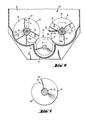
- FIG. 1 the structure of the entire device is clear.
- a filling opening 1 lies above the feed and metering device 2, which opens into the spray chamber 4.
- Under the spray chamber 4 is the mixing and delivery space 10, from which the seed is conveyed to the outlet 11.
- the feed and metering device 2 is formed by a horizontal screw conveyor consisting of a housing 37 and four screw conveyors 12-15. Above the screw conveyors 12-15 there is the filling opening 1 at their entrance. On the output side, the screw ends end above the opening 9 forming the entrance to the spray chamber 4. Between the openings 1 and 9, the screw conveyors 12-15 are formed by a constriction formed by a baffle 22 guided. At the filling opening 1, outside of the housing 37, gearwheels 40-43 interlocking on the shafts of the screw conveyors 12-15. They transmit the driving forces, the shaft 15 being driven by an electric motor 3 via a toothed belt 39. A gear 38 with an adjustable gear ratio converts the speed of rotation of the motor 3 to the desired level. A handwheel 44 is used for regulation.
- a value of 18 mm has been selected for the depth t (FIG. 4) of the screw conveyors 12-15 in the present exemplary embodiment of the device.
- the clumped seeds are then separated very well. At the same time, a high flow rate is achieved. Depths between approx. 10 mm and 30 mm are generally appropriate. That is about two to six times the size of a cotton seed. Values up to 50 mm can also be used will. In addition, the disintegration of the clumped seeds and thus the even distribution of the active ingredients is no longer guaranteed.
- this baffle 22 is equally essential for the separation of clumped seeds.
- the incisions between the conveyor screws or between a conveyor screw and the wall of the housing 37 are also covered in a comb shape.
- this baffle 22 due to its triangular combs between the screw shoulders and the opposite baffle 22, leaves a gap of only about 10 mm to 20 mm.
- the purpose of the baffle 22 is essentially to allow conveying only within the screw conveyors.
- the shape of the chicane 22 is not critical.
- the combs can follow the contours of the waves roughly in a semicircle so that the distance to the snail shoulders is constant. In this case, a distance of less than 5 times the size of a grain - about 20 mm for cotton - is well suited.
- the housing 37 closely follows the contours of the screws 12-15 over the entire length, so that no seed residues form on the housing walls during operation. This reduces cleaning work to a minimum.
- the conveyor screws 12-15 end above the opening 9 to the spray chamber 4.
- the two middle screws 13, 14 are shorter, as a result of which an even distribution over the cross section of the spray chamber 4 is achieved.
- Two plates 45, 46 guide the seed from the edge of the screw conveyor to the center in the opening 9.
- the housing of the spray chamber 4 is formed by a vertically standing hollow cylinder.
- the spray head 16 of a portable spraying device from MICRONAIR AERIAL LTD, model AU7000, is arranged in its center under a conical hood 23 and a short cylinder piece 48.
- the hood 23, cylinder piece 48 and spray head 16 are fastened to an assembly door 7 via an obliquely rising pipe section 49. Through this pipe section 49 drive shaft 28 and feed line 27 of the spray by means of the spray chamber 4 to the spray head 16.
- a fan 18 in the spray head 16 receives its intake air through this pipe section from an air inlet 29.
- a rotary cage atomizer 17 with two concentric cylindrical cages is arranged at the bottom on a vertical hollow axis.
- the outer cage consists of a fine wire mesh (hole size 1 mm2), the inner cage is formed by a perforated sheet.
- the fan 18 sits above it on the same axis.
- the atomizer 17 and fan 18 are driven together by a motor 5 arranged outside the chamber 4 via a toothed belt 19 and drive shaft 28.
- scrapers 8 run over the inside of the spray chamber wall and scrape residues from the wall in the spray area of the atomizer 17.
- the scrapers 8 are fastened on a ring gear 35 which is driven by an electric motor 34.
- the sprayer produces an extremely fine spray mist, the particle diameter of which is 5000 rpm. is on average about 100 microns. (This value applies to liquids with the viscosity of water. More viscous active ingredients form correspondingly larger droplets.)
- the liquid active ingredient reached the atomizer 17 via the feed line 27 and through the hollow axis 6.
- a major advantage of the rotary cage atomizer used is that that the droplet formation does not only occur in one plane as with rotating disks. It is possible through simple constructive measures such as to create smaller droplets by tighter meshes in the cages or, in the case of very viscous active ingredients, to use cages with larger hole diameters.
- the air inlet 29 of the fan 18 is connected via a hose 47 to an opening 36 at the outlet 11 of the entire device. From there, the fan 18 draws in air and drives and swirls the radially flying droplets of the atomizer 17 down into the mixing and Funding area. There the air returns along a screw conveyor 26 at the outlet 11 via the opening 36. The resulting air circuit prevents the air in the vicinity of the system from being contaminated with the active ingredient.
- the seed falls into the spray chamber 4 from above and is deflected outwards by the hood 23. Wetting begins at the level of the cage atomizer 17. It is supported by the air vortices generated by the fan 18. The wetted cotton seeds fall through an intermediate housing 20 into the mixing and delivery space 10.
- the mixing and delivery chamber 10 contains the screw conveyor 26, which leads at an angle of approximately 45 ° upwards to the outlet 11.
- the screw flights In the initial area 50, the screw flights have only a slight slope, in the exit area 51 they are steeper.
- Above the screw conveyor 26 and parallel to it are two further shafts 24, 25 which are alternately designed as screw flights 32 and paddle mixers 33.
- the worm threads 32 each run only over a full circumference of the shaft. Subsequently, three wing-like paddles 23 are distributed on the circumference of the shaft.
- the worm gear shoulder 56 and the front edge 54 of a worm gear 32 form a gradually rounded, flowing transition.
- the rear edge 55 and worm shoulder 56 are approximately at right angles to one another.
- the mixing shafts 24, 25 are restricted to the interior of the mixing and delivery space 10. They are driven by the worm conveyor 26 via gearwheels.
- a motor 21 drives the worm conveyor 26 at the output 11 via the same, adjustable gear as in the conveying and metering device 2.
- mixing and stirring of the seed compensates for non-uniformities in the wetting in the spray chamber and, on the other hand, distributes the spray mist that descends.
- the mixing shafts 24, 25 e.g. also be designed as a pure paddle mixer.
- the construction of the mixing device with only one mixing shaft is also conceivable, as are different rotational speeds of the individual shafts.
- the screw 26 conveys the seed only slowly towards the exit 11. This material influence is supported by the individual screw flights 32 on the mixing shafts 24, 25. Further up, the material flow is accelerated by the larger pitch (51) of the screw flights.
- the screw conveyor 26 runs on the underside in a narrowly tolerated channel, so that no or only the smallest possible residues form. For the same reason, the transition of the worm shoulder 56 to the front edge 54 of the worm threads 32 on the mixing shafts 24, 25 is slow and smooth. Due to the inclined rise of the screw conveyor 26, a small remnant of seed remains in the lower end of the mixing and delivery chamber 10. This remainder can be removed after opening a door 53. With steeper angles, the rest gets bigger. The angle should not exceed 60 °.
- the output 11 and the input 1 of the device are (due to the inclined position of the screw conveyor 26) at approximately the same level.
- the overall height of the overall arrangement can be optimally used, in particular when connecting a bag filling machine.
Landscapes
- Life Sciences & Earth Sciences (AREA)
- Soil Sciences (AREA)
- Environmental Sciences (AREA)
- Pretreatment Of Seeds And Plants (AREA)
- Nozzles (AREA)
- Mechanical Treatment Of Semiconductor (AREA)
Priority Applications (1)
| Application Number | Priority Date | Filing Date | Title |
|---|---|---|---|
| AT89810398T ATE72723T1 (de) | 1988-06-06 | 1989-05-29 | Vorrichtung zum benetzen von saatgut. |
Applications Claiming Priority (2)
| Application Number | Priority Date | Filing Date | Title |
|---|---|---|---|
| CH2140/88 | 1988-06-06 | ||
| CH214088 | 1988-06-06 |
Publications (2)
| Publication Number | Publication Date |
|---|---|
| EP0346278A1 true EP0346278A1 (fr) | 1989-12-13 |
| EP0346278B1 EP0346278B1 (fr) | 1992-02-26 |
Family
ID=4226811
Family Applications (1)
| Application Number | Title | Priority Date | Filing Date |
|---|---|---|---|
| EP89810398A Expired - Lifetime EP0346278B1 (fr) | 1988-06-06 | 1989-05-29 | Dispositif de traitement de semences |
Country Status (5)
| Country | Link |
|---|---|
| US (1) | US4987850A (fr) |
| EP (1) | EP0346278B1 (fr) |
| AT (1) | ATE72723T1 (fr) |
| DE (1) | DE58900855D1 (fr) |
| ES (1) | ES2029563T3 (fr) |
Cited By (5)
| Publication number | Priority date | Publication date | Assignee | Title |
|---|---|---|---|---|
| WO1994003274A1 (fr) * | 1992-07-30 | 1994-02-17 | Bühler AG | Procede et dispositif pour mouiller en continu des cereales et utilisation du dispositif mouille-grain |
| CN107926210A (zh) * | 2017-12-28 | 2018-04-20 | 深圳千色龙种子健康科技与服务有限公司 | 自动化种子包衣机 |
| RU2688319C1 (ru) * | 2018-06-27 | 2019-05-21 | Общество с ограниченной ответственностью "Биоагротехнология" | Увлажнительная машина для семян |
| CN111972078A (zh) * | 2020-09-05 | 2020-11-24 | 徐州蔬客达农业科技有限公司 | 一种谷物包衣机 |
| WO2024015230A1 (fr) * | 2022-07-13 | 2024-01-18 | Pivot Bio, Inc. | Systèmes, procédés de traitement de graines et compositions agricoles |
Families Citing this family (34)
| Publication number | Priority date | Publication date | Assignee | Title |
|---|---|---|---|---|
| US5192587A (en) * | 1991-08-23 | 1993-03-09 | Kurtz Bros., Inc. | Method for coloring wood chips |
| US5442995A (en) * | 1993-11-19 | 1995-08-22 | Biochem, Inc. | Apparatus for heat processing foodstuff |
| US6267495B1 (en) * | 1994-10-25 | 2001-07-31 | Process Control Corporation | Blender apparatus with precision low-rate metering unit |
| US6162496A (en) * | 1996-05-20 | 2000-12-19 | Blue; David | Method of mixing |
| US6517232B1 (en) | 1996-05-20 | 2003-02-11 | Becker-Underwood, Inc. | Mixing systems |
| AU750866B2 (en) * | 1998-05-22 | 2002-08-01 | Cnh Industrial Canada, Ltd. | In-line seed treating unit for air seeders |
| US6186655B1 (en) * | 1999-01-07 | 2001-02-13 | Owens Corning Fiberglass Technology, Inc. | Auger fed extruder |
| US6367959B1 (en) * | 2000-02-19 | 2002-04-09 | General Kinematics Corporation | Method and apparatus for blending water with sand |
| US6551401B1 (en) | 2000-10-19 | 2003-04-22 | Becker-Underwood, Inc. | Machine for coloring landscaping material |
| US6551402B1 (en) * | 2000-11-29 | 2003-04-22 | Usc, L.L.C. | Rotary atomizer |
| US20050276903A1 (en) * | 2003-08-20 | 2005-12-15 | Kraft Foods Holdings, Inc. | Method and apparatus for meat product manufacturing |
| US7871655B2 (en) * | 2003-08-20 | 2011-01-18 | Kraft Foods Global Brands Llc | Method and apparatus for accelerating formation of functional meat mixtures |
| US20050249862A1 (en) * | 2003-08-20 | 2005-11-10 | Kraft Foods Holdings, Inc. | Method and apparatus for controlling texture of meat products |
| US7731998B2 (en) * | 2003-08-20 | 2010-06-08 | Kraft Foods Global Brands Llc | Method for reducing protein exudate on meat product |
| US20050255222A1 (en) * | 2003-08-20 | 2005-11-17 | Kraft Foods Holdings, Inc. | Method and apparatus for acceleration ingredient diffusion in meat |
| US8172545B2 (en) * | 2003-08-20 | 2012-05-08 | Kraft Foods Global Brands Llc | Method for controlling ground meat flow rates |
| US20050255224A1 (en) * | 2003-08-20 | 2005-11-17 | Kraft Foods Holdings, Inc. | Integrated continuous meat processing system |
| US7488502B2 (en) * | 2003-08-20 | 2009-02-10 | Kraft Foods Global Brands Llc | Method of making processed meat products |
| US7169421B2 (en) * | 2003-08-20 | 2007-01-30 | Kraft Foods Holdings, Inc. | Method of making processed meat products |
| US7857500B2 (en) * | 2003-08-20 | 2010-12-28 | Kraft Foods Global Brands Llc | Apparatus for vacuum-less meat processing |
| CN101052474B (zh) * | 2004-08-17 | 2013-10-30 | 费尔蒙特矿物有限公司 | 快速作用涂布器 |
| US20060243301A1 (en) * | 2005-04-29 | 2006-11-02 | Lemond Shawn J | System and process for producing clean glass aggregate from recycled glass |
| US8187651B2 (en) * | 2008-11-24 | 2012-05-29 | Kraft Foods Global Brands Llc | Method and apparatus for continuous processing of whole muscle meat products |
| US8308342B2 (en) | 2008-11-24 | 2012-11-13 | Kraft Foods Global Brands Llc | Processing elements for mixing meat products |
| US8641263B2 (en) | 2008-11-24 | 2014-02-04 | Kraft Foods Group Brands Llc | Method and apparatus for continuous processing of whole muscle meat products |
| US9877424B2 (en) | 2010-12-08 | 2018-01-30 | Bayer Cropscience, Lp | Seed treatment facilities, methods and apparatus |
| US9959511B2 (en) | 2010-12-08 | 2018-05-01 | Bayer Cropscience Lp | Retail point seed treatment systems and methods |
| US9861027B2 (en) | 2010-12-08 | 2018-01-09 | Bayer Cropscience, Lp | Seed treatment systems and methods |
| US20130273236A1 (en) | 2012-04-16 | 2013-10-17 | Bayer Cropscience Lp | Seed treatment device with improved fluid application |
| US9420759B2 (en) * | 2012-06-06 | 2016-08-23 | Rusty D. Aton | Vehicle mounted feed hopper device |
| US9713893B2 (en) * | 2013-07-09 | 2017-07-25 | Wenger Manufacturing, Inc. | Method of preconditioning comestible materials using steam/water static mixer |
| US10694657B2 (en) | 2018-10-19 | 2020-06-30 | J&M Manufactuing Co., Inc. | Talc applicator for use with agricultural equipment and operations |
| US11291211B2 (en) * | 2019-05-24 | 2022-04-05 | Anko Food Machine Co., Ltd. | Dough kneading and feeding system of dough processing machine |
| WO2022140656A1 (fr) * | 2020-12-23 | 2022-06-30 | Pivot Bio, Inc. | Systèmes, procédés de traitement de graines et compositions agricoles |
Citations (5)
| Publication number | Priority date | Publication date | Assignee | Title |
|---|---|---|---|---|
| GB480203A (en) * | 1936-11-24 | 1938-02-18 | Bertie Norman Rodda | Improvements in auxiliary grain and/or fertilizer distributors for seed-sowing implements |
| US3155542A (en) * | 1960-09-22 | 1964-11-03 | Ben Gustason & Son Mfg Company | Cottonseed-treating machine |
| CH487673A (de) * | 1968-03-15 | 1970-03-31 | Buehler Ag Geb | Getreidewaschmaschine |
| FR2297791A1 (fr) * | 1975-01-20 | 1976-08-13 | Ranks Hovis Mcdougall Ltd | Convoyeur helicoidal pour le traitement de semences et appareil de traitement pourvu de ce convoyeur |
| DE3239867A1 (de) * | 1982-10-27 | 1984-05-03 | Gebrüder Bühler AG, Uzwil | Vorrichtung und anlage zum beizen von saatgut |
Family Cites Families (8)
| Publication number | Priority date | Publication date | Assignee | Title |
|---|---|---|---|---|
| US2538891A (en) * | 1948-02-19 | 1951-01-23 | Hoge Warren Zimmerman Co | Continuous mixing and delivering apparatus |
| US3009826A (en) * | 1957-05-24 | 1961-11-21 | Aeroprojects Inc | Process of forming a dispersion of aerosol particles and process for coating solid particles with said dispersion |
| NL246864A (fr) * | 1959-11-18 | |||
| JPS4748939B2 (fr) * | 1967-08-16 | 1972-12-08 | ||
| US3548782A (en) * | 1967-11-30 | 1970-12-22 | Hanningsen Foods Inc | Means for forming a continuous coating on particles |
| GB1251072A (fr) * | 1968-04-08 | 1971-10-27 | ||
| CH497261A (de) * | 1970-04-01 | 1970-10-15 | Stuedli Hans | Schneckengehäuse einer Doppelschneckenpresse |
| SU665835A1 (ru) * | 1976-06-17 | 1979-06-05 | Всесоюзный Ордена Трудового Красного Знамени Научно-Исследовательский Институт Сельскохозяйственного Машиностроения Им. В.П.Горячкина | Протравливатель сем н |
-
1989
- 1989-05-29 AT AT89810398T patent/ATE72723T1/de not_active IP Right Cessation
- 1989-05-29 DE DE8989810398T patent/DE58900855D1/de not_active Expired - Lifetime
- 1989-05-29 ES ES198989810398T patent/ES2029563T3/es not_active Expired - Lifetime
- 1989-05-29 EP EP89810398A patent/EP0346278B1/fr not_active Expired - Lifetime
- 1989-05-30 US US07/358,288 patent/US4987850A/en not_active Expired - Fee Related
Patent Citations (5)
| Publication number | Priority date | Publication date | Assignee | Title |
|---|---|---|---|---|
| GB480203A (en) * | 1936-11-24 | 1938-02-18 | Bertie Norman Rodda | Improvements in auxiliary grain and/or fertilizer distributors for seed-sowing implements |
| US3155542A (en) * | 1960-09-22 | 1964-11-03 | Ben Gustason & Son Mfg Company | Cottonseed-treating machine |
| CH487673A (de) * | 1968-03-15 | 1970-03-31 | Buehler Ag Geb | Getreidewaschmaschine |
| FR2297791A1 (fr) * | 1975-01-20 | 1976-08-13 | Ranks Hovis Mcdougall Ltd | Convoyeur helicoidal pour le traitement de semences et appareil de traitement pourvu de ce convoyeur |
| DE3239867A1 (de) * | 1982-10-27 | 1984-05-03 | Gebrüder Bühler AG, Uzwil | Vorrichtung und anlage zum beizen von saatgut |
Cited By (8)
| Publication number | Priority date | Publication date | Assignee | Title |
|---|---|---|---|---|
| WO1994003274A1 (fr) * | 1992-07-30 | 1994-02-17 | Bühler AG | Procede et dispositif pour mouiller en continu des cereales et utilisation du dispositif mouille-grain |
| TR27479A (tr) * | 1992-07-30 | 1995-06-07 | Buehler Ag Geb | Tahil ürününün sürekli olarak islatilmasina yarayan yöntem ile düzen ve bu nemlendirme düzeninin kullanimi. |
| AU664304B2 (en) * | 1992-07-30 | 1995-11-09 | Buhler Ag | Process and device for the continuous moistening of grain and use of the moistening device |
| US5538747A (en) * | 1992-07-30 | 1996-07-23 | Buehler Ag | Method and apparatus for the continuous damping of grain |
| CN107926210A (zh) * | 2017-12-28 | 2018-04-20 | 深圳千色龙种子健康科技与服务有限公司 | 自动化种子包衣机 |
| RU2688319C1 (ru) * | 2018-06-27 | 2019-05-21 | Общество с ограниченной ответственностью "Биоагротехнология" | Увлажнительная машина для семян |
| CN111972078A (zh) * | 2020-09-05 | 2020-11-24 | 徐州蔬客达农业科技有限公司 | 一种谷物包衣机 |
| WO2024015230A1 (fr) * | 2022-07-13 | 2024-01-18 | Pivot Bio, Inc. | Systèmes, procédés de traitement de graines et compositions agricoles |
Also Published As
| Publication number | Publication date |
|---|---|
| DE58900855D1 (de) | 1992-04-02 |
| ES2029563T3 (es) | 1992-08-16 |
| US4987850A (en) | 1991-01-29 |
| ATE72723T1 (de) | 1992-03-15 |
| EP0346278B1 (fr) | 1992-02-26 |
Similar Documents
| Publication | Publication Date | Title |
|---|---|---|
| EP0346278B1 (fr) | Dispositif de traitement de semences | |
| EP0971787B1 (fr) | Melangeur dynamique pour compositions pour empreintes dentaires | |
| DE10204921C1 (de) | Dispergier-Vorrichtung | |
| EP1932427B1 (fr) | Dispositif et procédé destinés à mettre des liquides dans des matières sèches pouvant s'écouler ou en vrac | |
| EP0157250B1 (fr) | Appareil de traitement de semences par des liquides | |
| DE2750696A1 (de) | Mehrstufiges verfahren und vorrichtung zum aufbringen eines spruehfaehigen mittels auf ein material aus losen granulat-, schuppen-, span- oder faserteilchen | |
| DE661846C (de) | Vorrichtung zum Mischen, Ruehren, Aufloesen, Eindicken, Kneten, Verreiben, Zerkleinern oder Versalben von fliessfaehigen oder bereits pulverfoermigen Massen, vorzugsweise zum Bearbeiten von Kakao- oder Schokolademassen | |
| EP0166017B1 (fr) | Dispositif pour la séparation de matériaux de mélange | |
| DE2453810C2 (de) | Beschickungsvorrichtung für eine Dispergiervorrichtung | |
| DE19629945C2 (de) | Mischvorrichtung zum Vermischen eines pulverförmigen und/oder körnigen Feststoffes mit einer Flüssigkeit | |
| DE2801460C2 (fr) | ||
| CH355771A (de) | Verfahren und Vorrichtung zur Behandlung von Stoffen und Stoffgemischen | |
| DE68913117T2 (de) | Verfahren und Vorrichtung zum Mischen von Pulver und Flüssigkeit. | |
| DE4000571C1 (fr) | ||
| DE2438818A1 (de) | Vorrichtung zum kontinuierlichen beleimen von fasern | |
| DE2239852A1 (de) | Mischwerkzeug fuer maschinen zum beleimen von spaenen | |
| DE19710067C1 (de) | Vorrichtung zum kontinuierlichen Anmachen von Schüttgut- oder Baustoffmischungen | |
| DE1940922C3 (de) | Kunstdüngerstreuer | |
| DE1196859B (de) | Verfahren und Vorrichtung zum UEberziehen von losen Teilchen, wie Holzspaenen od. dgl., mit einem spruehfaehigen Bindemittel | |
| DE69624445T2 (de) | Kontinuierlicher Mischer und Verfahren und Vorrichtung zum Beschichten von Materialpartikeln unter Verwendung desselben | |
| DE2621266A1 (de) | Vorrichtung zum ruehren, mischen und kneten teigiger massen | |
| AT224611B (de) | Vorrichtung zur Schwingungsbehandlung von fließfähigen Stoffen und Stoffgemischen | |
| EP0168601A2 (fr) | Dispositif pneumatique et évacuation pour centrifuge à racleur | |
| DE2707950C2 (de) | Vorrichtung zum Verstreuen von Streugut | |
| DE19835347A1 (de) | Vorrichtung zum Conchieren von Schokoladenmassen |
Legal Events
| Date | Code | Title | Description |
|---|---|---|---|
| PUAI | Public reference made under article 153(3) epc to a published international application that has entered the european phase |
Free format text: ORIGINAL CODE: 0009012 |
|
| 17P | Request for examination filed |
Effective date: 19890531 |
|
| AK | Designated contracting states |
Kind code of ref document: A1 Designated state(s): AT CH DE ES FR GB IT LI SE |
|
| 17Q | First examination report despatched |
Effective date: 19901221 |
|
| GRAA | (expected) grant |
Free format text: ORIGINAL CODE: 0009210 |
|
| AK | Designated contracting states |
Kind code of ref document: B1 Designated state(s): AT CH DE ES FR GB IT LI SE |
|
| REF | Corresponds to: |
Ref document number: 72723 Country of ref document: AT Date of ref document: 19920315 Kind code of ref document: T |
|
| ET | Fr: translation filed | ||
| ITF | It: translation for a ep patent filed | ||
| REF | Corresponds to: |
Ref document number: 58900855 Country of ref document: DE Date of ref document: 19920402 |
|
| GBT | Gb: translation of ep patent filed (gb section 77(6)(a)/1977) | ||
| REG | Reference to a national code |
Ref country code: ES Ref legal event code: FG2A Ref document number: 2029563 Country of ref document: ES Kind code of ref document: T3 |
|
| PLBE | No opposition filed within time limit |
Free format text: ORIGINAL CODE: 0009261 |
|
| STAA | Information on the status of an ep patent application or granted ep patent |
Free format text: STATUS: NO OPPOSITION FILED WITHIN TIME LIMIT |
|
| 26N | No opposition filed | ||
| PGFP | Annual fee paid to national office [announced via postgrant information from national office to epo] |
Ref country code: SE Payment date: 19930330 Year of fee payment: 5 |
|
| PG25 | Lapsed in a contracting state [announced via postgrant information from national office to epo] |
Ref country code: SE Effective date: 19940530 |
|
| PGFP | Annual fee paid to national office [announced via postgrant information from national office to epo] |
Ref country code: CH Payment date: 19940819 Year of fee payment: 6 |
|
| EUG | Se: european patent has lapsed |
Ref document number: 89810398.1 Effective date: 19941210 |
|
| EUG | Se: european patent has lapsed |
Ref document number: 89810398.1 |
|
| PGFP | Annual fee paid to national office [announced via postgrant information from national office to epo] |
Ref country code: FR Payment date: 19950407 Year of fee payment: 7 |
|
| PGFP | Annual fee paid to national office [announced via postgrant information from national office to epo] |
Ref country code: AT Payment date: 19950413 Year of fee payment: 7 |
|
| PGFP | Annual fee paid to national office [announced via postgrant information from national office to epo] |
Ref country code: DE Payment date: 19950424 Year of fee payment: 7 |
|
| PGFP | Annual fee paid to national office [announced via postgrant information from national office to epo] |
Ref country code: GB Payment date: 19950427 Year of fee payment: 7 |
|
| PGFP | Annual fee paid to national office [announced via postgrant information from national office to epo] |
Ref country code: ES Payment date: 19950516 Year of fee payment: 7 |
|
| PG25 | Lapsed in a contracting state [announced via postgrant information from national office to epo] |
Ref country code: LI Effective date: 19950531 Ref country code: CH Effective date: 19950531 |
|
| REG | Reference to a national code |
Ref country code: CH Ref legal event code: PL |
|
| PG25 | Lapsed in a contracting state [announced via postgrant information from national office to epo] |
Ref country code: GB Effective date: 19960529 Ref country code: AT Effective date: 19960529 |
|
| PG25 | Lapsed in a contracting state [announced via postgrant information from national office to epo] |
Ref country code: ES Free format text: LAPSE BECAUSE OF NON-PAYMENT OF DUE FEES Effective date: 19960530 |
|
| GBPC | Gb: european patent ceased through non-payment of renewal fee |
Effective date: 19960529 |
|
| PG25 | Lapsed in a contracting state [announced via postgrant information from national office to epo] |
Ref country code: FR Effective date: 19970131 |
|
| PG25 | Lapsed in a contracting state [announced via postgrant information from national office to epo] |
Ref country code: DE Effective date: 19970201 |
|
| REG | Reference to a national code |
Ref country code: FR Ref legal event code: ST |
|
| REG | Reference to a national code |
Ref country code: ES Ref legal event code: FD2A Effective date: 19990201 |
|
| PG25 | Lapsed in a contracting state [announced via postgrant information from national office to epo] |
Ref country code: IT Free format text: LAPSE BECAUSE OF NON-PAYMENT OF DUE FEES;WARNING: LAPSES OF ITALIAN PATENTS WITH EFFECTIVE DATE BEFORE 2007 MAY HAVE OCCURRED AT ANY TIME BEFORE 2007. THE CORRECT EFFECTIVE DATE MAY BE DIFFERENT FROM THE ONE RECORDED. Effective date: 20050529 |