EP0346046B1 - Kühlwalze - Google Patents
Kühlwalze Download PDFInfo
- Publication number
- EP0346046B1 EP0346046B1 EP89305651A EP89305651A EP0346046B1 EP 0346046 B1 EP0346046 B1 EP 0346046B1 EP 89305651 A EP89305651 A EP 89305651A EP 89305651 A EP89305651 A EP 89305651A EP 0346046 B1 EP0346046 B1 EP 0346046B1
- Authority
- EP
- European Patent Office
- Prior art keywords
- coolant
- roll
- chill roll
- header
- chill
- Prior art date
- Legal status (The legal status is an assumption and is not a legal conclusion. Google has not performed a legal analysis and makes no representation as to the accuracy of the status listed.)
- Expired - Lifetime
Links
- 239000002826 coolant Substances 0.000 claims description 162
- 239000000411 inducer Substances 0.000 claims description 8
- 230000002708 enhancing effect Effects 0.000 claims description 2
- 230000003068 static effect Effects 0.000 claims 1
- XLYOFNOQVPJJNP-UHFFFAOYSA-N water Substances O XLYOFNOQVPJJNP-UHFFFAOYSA-N 0.000 description 9
- OKTJSMMVPCPJKN-UHFFFAOYSA-N Carbon Chemical compound [C] OKTJSMMVPCPJKN-UHFFFAOYSA-N 0.000 description 8
- 229910052799 carbon Inorganic materials 0.000 description 8
- 238000001816 cooling Methods 0.000 description 6
- 239000012530 fluid Substances 0.000 description 5
- 230000001965 increasing effect Effects 0.000 description 5
- 230000000712 assembly Effects 0.000 description 2
- 238000000429 assembly Methods 0.000 description 2
- 230000000694 effects Effects 0.000 description 2
- 238000005728 strengthening Methods 0.000 description 2
- 230000005465 channeling Effects 0.000 description 1
- 238000012986 modification Methods 0.000 description 1
- 230000004048 modification Effects 0.000 description 1
- 239000007787 solid Substances 0.000 description 1
Images




Classifications
-
- B—PERFORMING OPERATIONS; TRANSPORTING
- B41—PRINTING; LINING MACHINES; TYPEWRITERS; STAMPS
- B41F—PRINTING MACHINES OR PRESSES
- B41F23/00—Devices for treating the surfaces of sheets, webs, or other articles in connection with printing
- B41F23/04—Devices for treating the surfaces of sheets, webs, or other articles in connection with printing by heat drying, by cooling, by applying powders
- B41F23/0476—Cooling
- B41F23/0479—Cooling using chill rolls
-
- F—MECHANICAL ENGINEERING; LIGHTING; HEATING; WEAPONS; BLASTING
- F26—DRYING
- F26B—DRYING SOLID MATERIALS OR OBJECTS BY REMOVING LIQUID THEREFROM
- F26B13/00—Machines and apparatus for drying fabrics, fibres, yarns, or other materials in long lengths, with progressive movement
- F26B13/10—Arrangements for feeding, heating or supporting materials; Controlling movement, tension or position of materials
- F26B13/14—Rollers, drums, cylinders; Arrangement of drives, supports, bearings, cleaning
- F26B13/18—Rollers, drums, cylinders; Arrangement of drives, supports, bearings, cleaning heated or cooled, e.g. from inside, the material being dried on the outside surface by conduction
- F26B13/183—Arrangements for heating, cooling, condensate removal
Definitions
- the present invention relates to a chill roll for cooling of printing webs, and more particularly, pertains to a chill roll with an outer roll rotating about an inner roll. Coolant is distributed evenly along the interior space between the inner and outer roll, and circulates circumferentially between the rolls to effect a uniform heat transfer across the rotating roll.
- Coolant was traditionally introduced into one side of the roll whereupon that end of the roll provided for cooling of the web adjacent to the coolant introduction area.
- the coolant temperature, as well as the web temperature across the web increased so that the exhaust end of the roller was warmer than the introduction end of the roller.
- the net effect was that one edge portion of the web was cooled quite well, but the opposing edge portion was cooled substantially less due to the temperature gradient differential across the chill roll.
- Other existing chill roll designs featured coolant passages which were located between the outer roll shell and an inner drum, and spiraled from one side of the roll to the other side.
- Still other existing chill roll structures had outer and inner drums which were rotated together, and as the coolant traveled across the roll, the coolant was heated by the web so that a temperature differential still existed between the roll surface on leaving and entering the ends.
- Prior art chill rolls merely pumped coolant into one end of the roll and simply forced it from the opposing end, which caused the area of the roll adjacent to the inlet to cool effectively.
- the coolant picked up heat from the roll
- the temperature of the area of the roll adjacent to the outlet end was much warmer than the area adjacent to the inlet. This temperature gradient across the roll would cause the web temperature to be variable in an increasing temperature differential, as well as across the roll and across the web.
- chill roll designs depended upon an excessive coolant flow to maintain an improved and more constant temperature differential across the chill roll. The greater the flow, the smaller the temperature differential across the roll. The present invention does not require increased coolant flow to maintain a low temperature differential because there is no differential. The same temperature exists across the roll at any given roll tangent.
- the present invention overcomes the disadvantages of the prior art devices by providing a chill roll which distributes coolant in an even and uniform fashion along and across the entire length of the chill roll interior so that heat transfer is accomplished circumferentially around and about an annular space and passage between an outer rotating chill roll and a stationary roll assembly. Heat transfer is further enhanced by turbulence inducer bars causing turbulence in the coolant flow between the stationary roll and the rotary roll.
- US-A-4120349 discloses a chill roll in which coolant passes along a narrow gap between (i) the internal surface of the cylindrical chill roll exterior and (ii) the external surface of a segment held stationary within that chill roll exterior, the direction of flow being such that the flow of coolant is counter-current to the direction of motion of the chill roll exterior. It is clear that this feature is only possible over a limited arc of the chill roll periphery, and there are various measures taken to confine the coolant to such a limited area and to remove any coolant which escapes from that limited area. US-A-4120349 uses stationary chill roll end journals in order to hold the chill roll inner segment stationary relative to the rotating chill roll exterior.
- Claim 1 has its pre-characterising portion based on US-A-4120349.
- the general purpose of the present invention is to provide a chill roll for uniform cooling across the width of an offset web.
- the chill roll includes a fluid flow system for delivery of coolant to an integral distribution fluid flow system contained in an inner stationary roll assembly which channels coolant from a coolant supply header, and across the longitudinal length of a chill roll.
- the coolant flows circumferentially in an annular space between a fixed and a rotary chill roll, and then returns through a coolant return header and return coolant exhaust.
- a chill roll comprising:
- the two end roll journals are:- a pin operator end journal and a drive end journal, each with internal passages, and they preferably extend through end plates at opposing ends of an outer rotary roll to support the bearing centre tube and stationary inner roll assembly, which encompasses the bearing centre tube.
- Supply coolant is introduced into the interior of the stationary inner roll through the drive end journal.
- the centre tube is preferably plugged at a mid-portion so as to divide the centre tube into a coolant supply chamber and a coolant return chamber. Holes in these coolant chambers connect to a coolant supply header or a coolant return header adjacent to the coolant supply and return chambers.
- Thrust washers and coolant-cooled carbon bearings are preferably positioned over and about the ends of the journals which extend through the rotary outer roll end plates.
- the centre tube including preferably weighted inner roll assembly components, remains stationary and can free-wheel within the outer rotating roll about the carbon bearings.
- the stationary chill roll assembly includes circular end discs at each end of the roll which secure to opposite ends of segmented cylindrical segments. The cylindrical segments also intersect the supply and return headers.
- Fluid flow is between an annular space of the inner stationary roll and the outer rotating roll. Fluid passes through the end journal, the centre tube, the coolant supply chamber, the coolant supply header, the annular space of the rolls, the coolant return header, the coolant return chamber, and an opposing end journal.
- Optional turbulence inducer bars about the cylindrical segments enhance heat transfer.
- Coolant flow is distributed in a substantially equal flow along the length of the chill roll.
- a substantially constant temperature differential is able to be maintained between the ends of the chill roll and along the length of the chill roll.
- Heat transfer is further enhanced by turbulence caused by an outer roll rotating about a fixed inner roll.
- Heat transfer may be still further enhanced by turbulence caused by the optional turbulence inducer bars in the coolant flow on the outer surface of an inner roll, on the inner surface of an outer roll, or likewise positioned in the coolant flow.
- Surface tension (between the rotating outer roll, the fixed inner roll and the interposed coolant) may move coolant by inertial feed between the rolls in the direction of rotation.
- FIG. 1 illustrates an exploded perspective view of the illustrated major components of a chill roll 10 for use in cooling a web, such as used in printing or other related fields.
- the chill roll 10 includes a cylindrical outer roll 12 which rotates coaxially about a cylindrical like inner roll assembly 14.
- the inner roll assembly 14 positions within the interior 16 of the cylindrical outer roll 12, and includes cylindrical segments 18a and 18b, each secured to the periphery of a channel like coolant supply header 20 and a channel like coolant return header 22.
- the coolant supply header 20 and the coolant return header 22 secure about a center tube 24.
- the center tube 24, the coolant supply header 20 and the coolant return header 22 include a plurality of orifices for the channeling or directing of coolant flows about the interior and exteriors of the center tube 24, the coolant supply header 20, and the coolant return header 22.
- a plurality of upper strengthening gussets 30a-30n and a plurality of lower strengthening gussets 32a-32n position across the coolant supply header 20 and the coolant return header 22 in the inner roll assembly 14.
- End discs 26 and 28 secure in a water tight manner over opposing ends of cylindrical segments 18a-18b, coolant supply header 20, coolant return header 22 and the center tube 24, each of the preceding elements being a member of the inner roll assembly 14.
- a weight 34 resembling a cylinder segment, positions in the bottom of the inner roll assembly 14 along the length of the cylindrical segment 18b to counter any rotational tendencies of the inner roll assembly 14.
- a circular end cap 36 including a drive end journal 38, affixes in one end of the cylindrical outer roll 12.
- a removable end cap 40 which includes an operator end journal 42, secures in the opposing end of the cylindrical outer roll 12.
- the drive end journal 38 and the operator end journal 42 extend through end caps 36 and 40, respectively, and into opposing ends of centrally aligned center tube 24 with water cooled carbon bearings 54 and 80 interposed to support the inner roll assembly 14.
- a cylindrical coolant supply orifice 44 concentric within the drive end journal 38, provides a path for supply coolant to enter the inner roll assembly 14 through the center tube 24.
- Turbulence inducer bars 48a-48n each being a part of the inner roll assembly 14, position longitudinally along the outer surfaces of the cylindrical segments 18a-18b.
- a coolant drain plug 50 locates in the removable end cap 40 to facilitate chill roll 10 drainage.
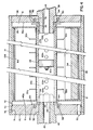
- FIG. 2 illustrates a partial cross-sectional view of the support of the inner roll assembly 14 by drive end journal 38 and operator end journal 42 taken through the vertical axis of the chill roll 10 of FIG. 1, where all numerals correspond to those elements previously described.
- Operator end journal 42 secures in a hole 52 and extends beyond the inner wall of the removable end 40.
- a shouldered water cooled carbon bearing 54 interposes between the annular surface 56 and the inner annular surface 58 of the center tube 24.
- a thrust washer 60 includes anti-rotational pins 62 and 64 engaged within holes 66 and 68 in the removable end cap 40, and intercedes between the water cooled carbon bearing 54 and the inner surface 40a of the removable end cap 40.
- Removable end cap 40 includes an annular groove 70 and an O-ring seal 72 providing a water tight seal between the removable end cap 40 and the outer roll 12. Threads 74, in the removable end cap 40, engage threads 76 on the interior of the outer roll 12. The drive end journal 38 frictionally engages within hole 78 and extends beyond the inner wall of the end cap 36.
- a shouldered water cooled carbon bearing 80 interposes between the annular surface 82 of the drive end journal 38 and the inner annular surface 84 of the center tube 24.
- a thrust washer 86 includes anti-rotational pins 88 and 90 engaged within holes 92 and 94 in the removable end cap 36.
- a wave washer 96 and the thrust washer 86 both interpose between the water cooled carbon bearing 80 and the inner surface 36a of the end cap 36.
- An expansion plug 100 installs in the mid-portion of the center tube 24, and divides the center tube into a coolant supply chamber 24a and a coolant return chamber 24b.
- the coolant supply chamber 24a includes a plurality of holes 102a-102n which port to the coolant supply header 20, which in this illustration aligns directly behind the holes 102a-102n.
- Coolant return chamber 24b also includes a plurality of holes 104a-104n oriented 180° from holes 102a-102n, the location of which are illustrated in FIGS. 3 and 4. Holes 104a-104n port the coolant return header 22.
- the plurality of holes 102a-102n and 104a-104n substantially align in a straight path along vertical tangents of the center tube 24, and also include additional holes included in the holes 102a-102n and 104a-104n radially displaced from the vertical tangential orientation.
- An annular coolant passage is formed between the outer roll 12 and the inner roll assembly 14.
- FIG. 3 illustrates a multi-view cross-sectional end view of the chill roll 10 including a cross section through the mid-portions of the coolant supply and return chambers 24a and 24b, and including the inner roll assembly 14 aligned in the outer roll 12 as viewed from the removable end cap 40. All numerals correspond to those elements previously described.
- the coolant supply header 20 includes a right angle member 110 and a planar member 112, both of which secure together at a joint 113 and to ridge areas 114 and 116 on the center tube 24.
- the coolant return header 22 also includes a right angle member 118 and a planar member 120, both of which secure together at a joint 115 and to ridge areas 114 and 116 on the center tube 24.
- the upper cylindrical segment 18a secures in an appropriate manner to the coolant supply header and return header 20 and 22 at joints 113 and 115. Additionally, joints 122 and 124 join the lower cylindrical segment 18b to the right angle members 110 and 118 of the coolant supply and return headers 20 and 22.
- a plurality of holes 126a-126n locate along the length of the right angle member 110 of the coolant supply header 20.
- Another plurality of holes 128a-128n locate along the length of the right angle member 118 of the coolant return header 22.
- FIG. 4 illustrates a cross-sectional view through the vertical axis of the chill roll 10 illustrating the center tube 24 in plan view in the left portion of the illustration, and engaged over and about the operator end journal 42. All numerals correspond to those elements previously described. A portion of the plurality of holes 104a-104n located on one side of the center tube 24 are illustrated. The coolant supply chamber 24a lies directly behind the plurality of holes 104a-104n in the center tube 24. Fluid travels to the coolant return chamber 24b through the plurality of holes 104a-104n from the coolant return header 22, illustrated in FIG. 4, which abuts perpendicularly and outwardly from the center tube 24 towards the viewer of the illustration.
- FIG. 5 illustrates the chill roll 10 supported for rotation between bearings 140 and 142 which are secured to side frames 144 and 146.
- a pulley 148 secures over the drive end journal 38 with a key 150 which engages in a keyway in the pulley 148 and a slot 152.
- the pulley 148 is rotated by an external motor imparting rotary motion to the outer roll 12 of the chill roll 10 while the weighted inner roll assembly 14 remains stationary.
- coolant is introduced and returned from the interior of the chill roll 10 through water tight rotary joints placed over and about the external portion of coolant supply and outlet orifices 44 and 46. Coolant flow is now described in detail in FIGS. 6 and 7.
- FIGS. 6 and 7 best illustrate the mode of operation of the chill roll 10 where all numerals correspond to those elements previously described.
- FIG. 6 illustrates a cross-sectional top view through the horizontal plane and axis of the chill roll 10 illustrating longitudinal and lateral flow of coolant through the chill roll 10.
- FIG. 7 illustrates a cross-sectional view of FIG. 3 illustrating circular flow of coolant 160 between the annular coolant passage 106, between the outer roll 12 and the inner roll assembly 14. It is noted that the outer roll 12 is in constant rotary motion on a common axis about the stationary inner roll assembly 14 as coolant flows through the chill roll 10. Coolant 160 is supplied to the coolant supply chamber 24a through the coolant supply orifice 44.
- Coolant proceeds and flows horizontally and longitudinally along the length of the coolant supply chamber 24a, and then flows horizontally and laterally through the plurality of holes 102a-102n, horizontally and laterally into the coolant supply header 20 where the uniform temperature coolant, not yet exposed to out-roll heat gradient, is uniformly directed and distributed horizontally and laterally through the plurality of holes 126a-126n and into the annular coolant passage 106.
- coolant 160 With reference to FIG. 7, movement of uniform temperature coolant 160 from holes 126a-126n located along the length of the coolant supply header 20, and rotary motion of the outer roll 12 by means of inertial feed causes coolant 160 to circumferentially traverse along the cylindrical segment 18a of the inner roll assembly 14, and within the annular coolant passage 106 to the plurality of holes 128a-128n in the coolant return header 22.
- the coolant 160 with a substantially increased temperature, is collected by the coolant return header 22 through holes 128a-128n.
- the warmed coolant 160 is collected and passes through holes 104a-104n into the coolant return chamber 24b and overboard through the coolant outlet orifice 46.
- Coolant 160 is distributed uniformly along the entire length of the inner roll assembly 14 by the holes 126a-126n in the coolant supply header 20, and causes heat transfer from the outer roll 12 to the coolant 160 to be uniform across the annular coolant passage 106. A portion of the coolant proceeds full circle beyond the coolant return header 22, past and by the cylindrical segment 18b of the inner roll assembly 14, and also continues to remove heat from the outer roll 12 in a uniform fashion. The temperature across the rotating outer roll is uniformly lowered by uniform heat transfer accomplished by uniform heat removal by the coolant 160 in the annular coolant passage 106. Coolant flow turbulence is generated between the rotating outer roll 12 and the inner roll assembly 14.
- turbulence inducer bars 48a-48n located longitudinally along the cylindrical segments 18a and 18b.
- the turbulence inducer bars 48a-48n can be located on the inner surface of the outer roll 12 to accomplish the same turbulence generation.
- the turbulence inducer bars 48a-48n can also be suspended in the coolant flow between the outer and inner roll assemblies.
- FIG. 8 illustrates an alternative embodiment of a chill roll 170, where all numerals correspond to those elements previously described, featuring a solid operator end journal 172 and a drive end journal 174 with concentric supply and return passage tubes or orifices.
- a coolant return tube 176 is concentrically aligned in hole 178 of the drive end journal 174 and terminates in hole 180 of a plug 181, and connects to the coolant return chamber 24b.
- Plug 181 divides the center tube 24 into a coolant supply chamber 24a and a coolant return chamber 24b.
- An annular coolant supply chamber 182 locates concentrically in the drive end journal 174 between the sides of the hole 178 and about the outer circumference of the return tube 176.
- coolant 160 enters the annular coolant supply chamber 182, proceeds into the coolant supply chamber 24a, and flows through holes 102a-102n, through coolant supply header 20, through holes 126a-126n, through annular coolant passage 106 circumferentially about the inner roll assembly 14 as previously described, through holes 104a-104n and into the coolant return chamber 24b.
- Coolant 160 proceeds from the coolant return chamber 24b through an orifice 184 in and through the return tube 176.
- An external rotary joint connects over the drive end journal 174 for passage of the coolant 160 in their respective directions through the annular coolant supply chamber 182 and return tube 176.
- the chill roll can be used as a paper or web dryer.
- the chill roll can also be utilized in other applications in addition to the printing industry.
- the turbulence bars can be arranged in any geometrical configuration to enhance heat transfer.
Landscapes
- Engineering & Computer Science (AREA)
- Mechanical Engineering (AREA)
- Textile Engineering (AREA)
- General Engineering & Computer Science (AREA)
- Supply, Installation And Extraction Of Printed Sheets Or Plates (AREA)
- Rolls And Other Rotary Bodies (AREA)
- Continuous Casting (AREA)
- Accessory Devices And Overall Control Thereof (AREA)
Claims (7)
- Kühlwalze mit:(a) einer zylindrischen, rotierenden äußeren Kühlwalze (12);(b) gegenüberliegenden, zylindrischen ersten und zweiten Lagerzapfen (38, 42; 172, 174), die die Kühlwalze unterstützen und mit einem Kühlmitteleinlaß (44) bzw. einem Kühlmittelauslaß (46) in dem ersten bzw. dem zweiten Lagerzapfen versehen sind;(c) einem inneren, stationären Walzensegment (14), das eine zylindrische Außenfläche aufweist, deren Durchmesser geringer ist als der der äußeren Kühlwalze, um einen ringförmigen Freiraum dazwischen freizulassen;
gekennzeichnet durch(d) die Tatsache, daß zwei dieser Segmente vorhanden sind, nämlich gegenüberliegende untere und obere zylindrische Segmente, die jeweils an einer Kühlmittelverteilerleitung (20) und einer Kühlmittelsammelleitung (22) befestigt sind, wobei die Leitungen um ein zentrales Rohr (24) befestigt sind, das von den Lagerzapfen getragen wird; durch(e) die Tatsache, daß die ersten und zweiten Lagerzapfen drehbar sind; durch(f) eine Mehrzahl von Löchern (102a ... 102n) in einer Kühlmittelzufuhrkammer (24a) in einem ersten Bereich des zentralen Rohrs und einer entsprechenden Mehrzahl von Löchern (104a ... 104n) in einer Kühlmittelrückführkammer (24b) in einem zweiten Bereich des zentralen Rohrs; und durch(g) eine Mehrzahl von Löchern (126a ... 126n; 128a ... 128n) in der Kühlmittelverteilerleitung und in der Kühlmittelsammelleitung, wodurch Kühlmittel durch den ersten Lagerzapfen (38), die Kühlmittelzufuhrkammer (24a), die Kühlmittelverteilerleitung, den Freiraum zwischen den Walzen (12, 14), die Kühlmittelsammelleitung, die Kühlmittelrückführkammer (24b) und heraus durch den zweiten Lagerzapfen (42) fließt und wodurch die stationäre innere Walze (14) Kühlmittel über die rotierende äußere Walze (12) verteilt und sammelt, wodurch die Wärmeübertragung gleichmäßig erhöht wird. - Kühlwalze nach Anspruch 1, mit Mitteln (48a ... 48n) zum Erzeugen einer starken Turbulenz in dem ringförmigen Freiraum zwischen der rotierenden Walze (12) und der stationären Walze (14), wodurch die Turbulenz erzeugenden Mittel eine erhöhte Wärmeübertragung schaffen.
- Kühlwalze nach Anspruch 2, wobei die Turbulenz erzeugenden Mittel an der Außenfläche der inneren Walze angeordnet sind.
- Kühlwalze nach Anspruch 2, wobei die Turbulenz erzeugenden Mittel an der Innenfläche der äußeren Walze angeordnet sind.
- Kühlwalze nach einem der Ansprüche 2 bis 4, wobei die Turbulenz erzeugenden Mittel turbulenzinduzierende Stege (48a..., 48n) aufweisen.
- Kühlwalze nach einem der Ansprüche 1 bis 5, wobei ein erster zylindrischer Antriebslagerzapfen einen koaxialen Kühlmitteleinlaß und -auslaß darin aufweist; und ein Kühlmittelrückführrohr (176) enthält, das konzentrisch in einer Öffnung (178) des ersten Lagerzapfens (174) angeordnet ist und an einer Öffnung (180) in einem Verschlußstopfen (181) in einem mittleren Bereich des zentralen Rohrs (24) endet; wobei sich die Kühlmittelzufuhrkammer (24a) zwischen dem Kühlmittelrückführrohr und dem zentralen Rohr befindet und die Kühlmittelverteilerleitung (20) um den äußeren Umfang des zentralen Rohrs angeordnet ist; und wobei die Kühlmittelrückführkammer (24b) sich in dem zentralen Rohr und zwischen dem Verschlußstopfen (181) und dem zweiten Lagerzapfen (172) befindet, und die Kühlmittelsammelleitung (22) um den äußeren Umfang des zentralen Rohrs angeordnet ist.
- Kühlwalze nach einem der Ansprüche 1 bis 6 mit einem Gewicht (34) in dem unteren zylindrischen Segment (18b).
Applications Claiming Priority (2)
| Application Number | Priority Date | Filing Date | Title |
|---|---|---|---|
| US20307588A | 1988-06-07 | 1988-06-07 | |
| US203075 | 1988-06-07 |
Publications (3)
| Publication Number | Publication Date |
|---|---|
| EP0346046A2 EP0346046A2 (de) | 1989-12-13 |
| EP0346046A3 EP0346046A3 (en) | 1990-02-28 |
| EP0346046B1 true EP0346046B1 (de) | 1993-10-27 |
Family
ID=22752387
Family Applications (1)
| Application Number | Title | Priority Date | Filing Date |
|---|---|---|---|
| EP89305651A Expired - Lifetime EP0346046B1 (de) | 1988-06-07 | 1989-06-05 | Kühlwalze |
Country Status (4)
| Country | Link |
|---|---|
| EP (1) | EP0346046B1 (de) |
| JP (1) | JPH0225333A (de) |
| CA (1) | CA1310840C (de) |
| DE (1) | DE68910193T2 (de) |
Families Citing this family (11)
| Publication number | Priority date | Publication date | Assignee | Title |
|---|---|---|---|---|
| DE19812149A1 (de) * | 1998-03-20 | 1999-09-23 | Heidelberger Druckmasch Ag | Kühlwalze |
| DE10305917B4 (de) * | 2002-03-13 | 2015-06-25 | Goss Contiweb B.V. | Kühlwalze mit einem im Wesentlichen hohlen Innenraum |
| JP4598574B2 (ja) | 2005-03-17 | 2010-12-15 | 東芝機械株式会社 | 加熱、冷却ロール |
| JP5339204B2 (ja) * | 2009-08-05 | 2013-11-13 | 株式会社リコー | 冷却装置及び画像形成装置 |
| JP5483174B2 (ja) * | 2009-11-11 | 2014-05-07 | 株式会社リコー | 冷却装置及び画像形成装置 |
| US8606138B2 (en) | 2009-08-05 | 2013-12-10 | Ricoh Company, Limited | Cooling device having a turbulence generating unit |
| JP5557098B2 (ja) * | 2010-07-07 | 2014-07-23 | 株式会社リコー | 冷却装置及び画像形成装置 |
| AT514810B1 (de) * | 2013-09-23 | 2015-04-15 | Blum Gmbh Julius | Schwimmend gelagerte Abstützrolle |
| CN115091738B (zh) * | 2022-06-16 | 2023-07-21 | 浙江启德新材料有限公司 | 一种透明pvc装饰膜加工装置及生产方法 |
| DE102022211429A1 (de) * | 2022-10-27 | 2024-05-02 | Bhs Corrugated Maschinen- Und Anlagenbau Gmbh | Temperierwalzen-Anordnung |
| CN119329032B (zh) * | 2024-08-30 | 2025-04-04 | 绍兴冠越达薄膜科技有限公司 | 一种冷却辊 |
Citations (3)
| Publication number | Priority date | Publication date | Assignee | Title |
|---|---|---|---|---|
| US2915293A (en) * | 1957-04-10 | 1959-12-01 | Beloit Iron Works | Drying drum and method |
| FR2187097A5 (de) * | 1970-07-17 | 1974-01-11 | Gatineau Ets Sa | |
| DE2927198A1 (de) * | 1979-07-05 | 1981-01-15 | Maschf Augsburg Nuernberg Ag | Kuehlwalze mit einem aeusseren walzenmantel und einem innenkoerper |
Family Cites Families (6)
| Publication number | Priority date | Publication date | Assignee | Title |
|---|---|---|---|---|
| GB869890A (en) * | 1957-12-03 | 1961-06-07 | Inta Roto Machine Company Inc | Improvements in and relating to heat exchange rolls |
| DE2209498A1 (de) * | 1972-02-29 | 1973-09-06 | Maschf Augsburg Nuernberg Ag | Kuehlwalze fuer warenbahnen |
| JPS4926655A (de) * | 1972-07-06 | 1974-03-09 | ||
| US4120349A (en) * | 1976-10-12 | 1978-10-17 | Beloit Corporation | Heat transfer roll |
| JPS57146433A (en) * | 1981-03-06 | 1982-09-09 | Oki Electric Ind Co Ltd | Manufacture of snap disk |
| JPS608045A (ja) * | 1983-06-27 | 1985-01-16 | Nitto Electric Ind Co Ltd | 粘着フイルム貼付方法 |
-
1989
- 1989-06-05 EP EP89305651A patent/EP0346046B1/de not_active Expired - Lifetime
- 1989-06-05 DE DE1989610193 patent/DE68910193T2/de not_active Expired - Fee Related
- 1989-06-06 CA CA000601904A patent/CA1310840C/en not_active Expired - Lifetime
- 1989-06-07 JP JP14504889A patent/JPH0225333A/ja active Pending
Patent Citations (3)
| Publication number | Priority date | Publication date | Assignee | Title |
|---|---|---|---|---|
| US2915293A (en) * | 1957-04-10 | 1959-12-01 | Beloit Iron Works | Drying drum and method |
| FR2187097A5 (de) * | 1970-07-17 | 1974-01-11 | Gatineau Ets Sa | |
| DE2927198A1 (de) * | 1979-07-05 | 1981-01-15 | Maschf Augsburg Nuernberg Ag | Kuehlwalze mit einem aeusseren walzenmantel und einem innenkoerper |
Also Published As
| Publication number | Publication date |
|---|---|
| JPH0225333A (ja) | 1990-01-26 |
| DE68910193T2 (de) | 1994-02-17 |
| EP0346046A3 (en) | 1990-02-28 |
| CA1310840C (en) | 1992-12-01 |
| DE68910193D1 (de) | 1993-12-02 |
| EP0346046A2 (de) | 1989-12-13 |
Similar Documents
| Publication | Publication Date | Title |
|---|---|---|
| EP0346046B1 (de) | Kühlwalze | |
| DE69309758T2 (de) | Verfahren und Vorrichtung zur Trocknung von Papier | |
| US4913224A (en) | Chill roll | |
| CN105665666B (zh) | 一种用于非晶带材制备的均匀冷却的冷却辊装置及方法 | |
| JP3446119B2 (ja) | ローラー装置及びこの装置を有する輪転機 | |
| US4712475A (en) | Inking roller for printing machines | |
| US3633663A (en) | Cooling roll | |
| FI90835C (fi) | Telalla tai kahden telan välissä tapahtuvan jatkuvan valamisen laitteen tela | |
| US4640345A (en) | Rotating heat exchanger | |
| US4491171A (en) | Regenerator with a rotating regenerative heat exchanger | |
| GB2128521A (en) | Continuous casting machine for battery grids | |
| EP0128211B1 (de) | Rotierender wärmeaustauscher | |
| KR100546870B1 (ko) | 스틸 스트립 주조용 무축 주조롤 및 이것을 이용한 주조 장치 | |
| US5370177A (en) | Controllable-temperature roll | |
| US4760631A (en) | Roll | |
| SE446223B (sv) | Vermevexlarcylinder | |
| US3040553A (en) | Sealing of pressure vessels | |
| CN109153253B (zh) | 用于印刷机的冷却辊 | |
| FI85892C (fi) | Upphettbar poler- eller kalandervals. | |
| JP3388595B2 (ja) | 加熱、冷却ロール | |
| US4093023A (en) | Sheet mill table roll | |
| JPH0268390A (ja) | 熱媒によって加熱されるヒートローラ | |
| SU1388316A1 (ru) | Барабан дл термообработки полимерных материалов | |
| US4265175A (en) | Central support arrangement for printing systems | |
| US20070149376A1 (en) | Vacuum cooling roller |
Legal Events
| Date | Code | Title | Description |
|---|---|---|---|
| PUAI | Public reference made under article 153(3) epc to a published international application that has entered the european phase |
Free format text: ORIGINAL CODE: 0009012 |
|
| AK | Designated contracting states |
Kind code of ref document: A2 Designated state(s): DE FR GB IT |
|
| PUAL | Search report despatched |
Free format text: ORIGINAL CODE: 0009013 |
|
| AK | Designated contracting states |
Kind code of ref document: A3 Designated state(s): DE FR GB IT |
|
| 17P | Request for examination filed |
Effective date: 19900502 |
|
| 17Q | First examination report despatched |
Effective date: 19911118 |
|
| GRAA | (expected) grant |
Free format text: ORIGINAL CODE: 0009210 |
|
| AK | Designated contracting states |
Kind code of ref document: B1 Designated state(s): DE FR GB IT |
|
| REF | Corresponds to: |
Ref document number: 68910193 Country of ref document: DE Date of ref document: 19931202 |
|
| ITF | It: translation for a ep patent filed | ||
| ET | Fr: translation filed | ||
| PLBE | No opposition filed within time limit |
Free format text: ORIGINAL CODE: 0009261 |
|
| STAA | Information on the status of an ep patent application or granted ep patent |
Free format text: STATUS: NO OPPOSITION FILED WITHIN TIME LIMIT |
|
| 26N | No opposition filed | ||
| PGFP | Annual fee paid to national office [announced via postgrant information from national office to epo] |
Ref country code: GB Payment date: 19950525 Year of fee payment: 7 |
|
| PGFP | Annual fee paid to national office [announced via postgrant information from national office to epo] |
Ref country code: DE Payment date: 19950607 Year of fee payment: 7 |
|
| PGFP | Annual fee paid to national office [announced via postgrant information from national office to epo] |
Ref country code: FR Payment date: 19950609 Year of fee payment: 7 |
|
| PG25 | Lapsed in a contracting state [announced via postgrant information from national office to epo] |
Ref country code: GB Effective date: 19960605 |
|
| GBPC | Gb: european patent ceased through non-payment of renewal fee |
Effective date: 19960605 |
|
| PG25 | Lapsed in a contracting state [announced via postgrant information from national office to epo] |
Ref country code: FR Effective date: 19970228 |
|
| PG25 | Lapsed in a contracting state [announced via postgrant information from national office to epo] |
Ref country code: DE Effective date: 19970301 |
|
| REG | Reference to a national code |
Ref country code: FR Ref legal event code: ST |
|
| PG25 | Lapsed in a contracting state [announced via postgrant information from national office to epo] |
Ref country code: IT Free format text: LAPSE BECAUSE OF NON-PAYMENT OF DUE FEES Effective date: 20050605 |