EP0345752B1 - Optische Informationsaufzeichnungsmethode und Gerät und Aufzeichnungsmedium dafür - Google Patents
Optische Informationsaufzeichnungsmethode und Gerät und Aufzeichnungsmedium dafür Download PDFInfo
- Publication number
- EP0345752B1 EP0345752B1 EP89110279A EP89110279A EP0345752B1 EP 0345752 B1 EP0345752 B1 EP 0345752B1 EP 89110279 A EP89110279 A EP 89110279A EP 89110279 A EP89110279 A EP 89110279A EP 0345752 B1 EP0345752 B1 EP 0345752B1
- Authority
- EP
- European Patent Office
- Prior art keywords
- recording
- power
- film
- recording position
- temperature
- Prior art date
- Legal status (The legal status is an assumption and is not a legal conclusion. Google has not performed a legal analysis and makes no representation as to the accuracy of the status listed.)
- Expired - Lifetime
Links
Images


Classifications
-
- G—PHYSICS
- G11—INFORMATION STORAGE
- G11B—INFORMATION STORAGE BASED ON RELATIVE MOVEMENT BETWEEN RECORD CARRIER AND TRANSDUCER
- G11B11/00—Recording on or reproducing from the same record carrier wherein for these two operations the methods are covered by different main groups of groups G11B3/00 - G11B7/00 or by different subgroups of group G11B9/00; Record carriers therefor
- G11B11/03—Recording on or reproducing from the same record carrier wherein for these two operations the methods are covered by different main groups of groups G11B3/00 - G11B7/00 or by different subgroups of group G11B9/00; Record carriers therefor using recording by deforming with non-mechanical means, e.g. laser, beam of particles
-
- G—PHYSICS
- G11—INFORMATION STORAGE
- G11B—INFORMATION STORAGE BASED ON RELATIVE MOVEMENT BETWEEN RECORD CARRIER AND TRANSDUCER
- G11B7/00—Recording or reproducing by optical means, e.g. recording using a thermal beam of optical radiation by modifying optical properties or the physical structure, reproducing using an optical beam at lower power by sensing optical properties; Record carriers therefor
- G11B7/12—Heads, e.g. forming of the optical beam spot or modulation of the optical beam
- G11B7/125—Optical beam sources therefor, e.g. laser control circuitry specially adapted for optical storage devices; Modulators, e.g. means for controlling the size or intensity of optical spots or optical traces
- G11B7/126—Circuits, methods or arrangements for laser control or stabilisation
-
- G—PHYSICS
- G11—INFORMATION STORAGE
- G11B—INFORMATION STORAGE BASED ON RELATIVE MOVEMENT BETWEEN RECORD CARRIER AND TRANSDUCER
- G11B7/00—Recording or reproducing by optical means, e.g. recording using a thermal beam of optical radiation by modifying optical properties or the physical structure, reproducing using an optical beam at lower power by sensing optical properties; Record carriers therefor
- G11B7/004—Recording, reproducing or erasing methods; Read, write or erase circuits therefor
- G11B7/006—Overwriting
-
- G—PHYSICS
- G11—INFORMATION STORAGE
- G11B—INFORMATION STORAGE BASED ON RELATIVE MOVEMENT BETWEEN RECORD CARRIER AND TRANSDUCER
- G11B7/00—Recording or reproducing by optical means, e.g. recording using a thermal beam of optical radiation by modifying optical properties or the physical structure, reproducing using an optical beam at lower power by sensing optical properties; Record carriers therefor
- G11B7/24—Record carriers characterised by shape, structure or physical properties, or by the selection of the material
Definitions
- the present invention relates to a method and apparatus for optically recording information and a recording medium therefor, and more particularly to those which permit overwrite using a single beam and can provide high overwrite erasing capability.
- phase-change film As a technique of optically recording and reproducing information, it is known to use a phase-change film as a recording medium, and change laser irradiation power to cause the phase change thereof, thereby changing the optical property thereof so as to record and reproduce information.
- the technique of overwriting new data on old data while modulating the irradiation intensity of a single laser beam is disclosed in the technical search reports by the Japanese literature "DENSI JOHO TSUSIN GAKKAI, SINGAKU GIHO", Vol. 87, No. 310 CPM87-88, 88, 89, 90.
- a laser beam having the power profile as shown in Fig. 22 is irradiated onto the optical disk (recording medium) having a phase-change recording film, as shown in Fig. 21.
- the power profile of this laser beam is such that the pulsating power P, for recording information at a recording position to be amorphous is superposed on the D.C. power P 2 for recording information to be crystalline.
- Fig. 23 shows a relation between the pulse width and power of laser radiation for the recording film and the phase change thereof.
- the recording film can be changed to be crystalline or amorphous.
- making or becoming crystalline is referred to as “crystallizing” and making or becoming amorphous is referred to as “amorphousizing”.
- the prior art technique discloses the basic operation of implementing the phase-change single beam overwrite but has the following problem. Any consideration is not given for the property of the recording film and the recording condition which are required to provide a high erasing ratio, i.e. for the realization of sufficiently high erasing ratio required in actually performing the phase-change single beam overwrite. Thus, the prior art provides a low erasing ratio and so, a large error rate due to incomplete erasure of old data. Accordingly, the prior art cannot satisfy the required reliability.
- the recording process in the phase-change recording system is roughly represented by the crystallization state of the recording film.
- the crystallization state can be expressed by formula of JMA (Johnson, Mehl and Avrami) as disclosed in the reference of Japan Journal of Applied Physics, Vol. 26 (1987) Supplement 26-4.
- the crystallization time ⁇ (T) at the temperature T(K) of the recording film can be expressed by where crystal nucleous frequency factor Ea: activation energy
- Fig. 24 shows a relation between the temperature T and the crystallization time ⁇ (T) in Equation (1).
- the temperature (abscissa) is represented by 1000/T.
- the crystallization time ⁇ (T) is shortened.
- the crystallization time i(T) is lengthened since the dissociation probabi lity of atoms is increased as the temperature approaches the melting point Tm of the recording film.
- Equation (1) represents that the temperature where the crystallization time r(T) is shortest and so the recording film is easily crystallized is located at the temperature slightly lower than the melting point Tm.
- This temperature where the crystallization time T (T) is shortest is referred to as a nose temperature Tn since it looks like a nose tip.
- Tn is the root of the following Equation (2) when the differentiation of Equation (1) is set at zero.
- Fig. 26 shows a relation between Q x k/Ea and the nose temperature Tn obtained using formula of Cardann.
- the crystallization rate X when the temperature is held at the temperature Tfor a time t is represented by where n: reaction constant.
- n 2-3.
- the crystallization of a recording film when it is heated from a room temperature to high temperatures through laser irradiation thereto accords with the integration of the crystallization rates at the respective temperatures in Equation (3) in accordance with the temperature profile.
- a phase-change optical disk laser heating is completed in a short time within 1 microsecond and the maximum heating temperature exceeds the melting point, so that the crystallization through the temperature profile occurs in the neighborhood of the nose temperature Tn where the crystallization time ⁇ (Tn) is shortest.
- the approximation 8t/ ⁇ (T) « 1 can be taken and so the crystallization rate 8X is substantially zero. Therefore, this temperature region does not contribute to the crystallization.
- the temperature region participating in the crystallization where the crystallization time r(T) ⁇ (10 x ⁇ (Tn)) is referred to as a crystallization temperature region or zone.
- Ea the activation energies
- Q the activation constant
- Fig. 22 shows the power profile of the irradiated laser during the single beam overwrite. This profile consists of two levels of power P 2 continuously light- emitting for crystallizing and power P 1 for amorphousizing superposed with recording pulses thereon.
- Fig. 30Aand 30B schematically show the temperature of the recording film when the crystallizing power P 2 and amorphousizing power P 1 are irradiated in accordance with the laser power profile shown in Fig. 22, and the crystallization rate represented by the previously mentioned formula of JMA.
- the rotation numberofthe disk is set at 1800 rpm
- the linearspeed is set at 10 m/s
- the laser spot diameter is set at 1 ⁇ m.
- the time t c 1 passing the crystallization temperature region which is the time when the laser spot passes at the linear speed of 10 m/s, is about 0.1 ⁇ s.
- the resulting temperature profile is the temperature profile in the crystallizing mode superposed with the temperature profile corresponding to the pulse component. Since the recording film is once melted at the temperature of the melting point or more, the time required to pass the crystallization temperature region has only to be considered on the cooling process after the melting. Thus, the time t c 2 passing the crystallization temperature region is about 0.05 ⁇ s, which is about 1/2 or t c 1.
- the single beam overwrite can not change the laser spot diameter for the amorphousizing mode in which the recording position is made amorphous and the crystallizing mode in which the recording position is made crystalline, the passing time in the crystallization temperature region varies only about double between the amorphousizing and crystallizing modes, namely can not greatly vary.
- the crystallization time ⁇ (Tn) is previously defined with the recording film, and the passing time t c varies only about double as mentioned above. Therefore, the crystallization in the crystallizing and amorphousizing modes in accordance with the power profile of the single beam overwrite as shown in Fig. 22 can not provide the crystallization rate of 100% in the crystallizing mode and that of 0% (amorphous) in the amorphousizing mode, as shown in Figs. 30A and 30B.
- the passing time t c in the crystallizing mode i.e. t » ⁇ (Tn) is satisfied.
- the passing time t c » ⁇ (Tn) results also in the amorphousizing mode.
- the crystallization rate at the recording position becomes almost equal to that in crystallizing mode and thus, there is no difference of the crystallization rate between the crystallizing and amorphousizing modes. Since recording/reproduction uses that difference of the crystallization rate leads to that of a reflection coefficient, the absence of difference in the crystallization rate substantially makes it impossible to record and reproduce signals.
- the recording film at the recording position is once melted to enter the liquid phase and is recrystallized in the abrupt cooling process from the liquid phase to the solid phase so that its crystallization rate remains constant and is 40%.
- the film is not melted and one round process of the crystallizing mode can not provide complete crystalline state with the crystallization rate of 100% so that the influence of the old crystallization rate of the recording position before new crystallization is left as a previous history. If the previous phase at the recording position is crystalline as previous history, the crystallization rate has already reached 80% and the remaining 20% part of amorphous portion which is not still crystallized is facilitated to be crystallized.
- the crystallization rate of the amorphous portion is 80% when the new crystallizing is carried out by once irradiating laser.
- the new crystallization rate after having experienced the crystallizing mode becomes 96% (the initial crystallization rate of 80% plus the crystallization facilitating rate of 16% for the uncrystallized portion).
- the initial crystallization rate is 40%, and the new crystallization rate after having experienced the crystallizing mode this time becomes 88% (the initial crystallization rate of40% plus the crystallization facilitating rate of 48%).
- EP-A-0 265 971 discloses an overwrite method operating with three different power levels. The method starts with applying an erase power level, then a recording power level is applied and finally a low cooling power level in applied. The recording power level exceeds the melting power level. The erase power level causes the film to become crystalline by heating it to the crystallisation temperature region. The recording power level causes the film to become melted and the subsequent cooling power causes the film to be quenched thereby resulting in an amorphous state. In the document it is indicated that in some cases the erase power level can be sligthly above the melting power level. However, the melting conditions remain different for the erase power level and the recording power level.
- An object of the present invention is to provide a method and apparatus for optically recording information and a recording medium therefor which permit overwrite using a single beam with a high erasing ratio.
- the operation point of irradiated laser power is set for both amorphousizing mode and crystallizing mode at power which permits a recording film to be heated at a temperature or its melting point or more and also the heat dissipating property of the recording film and its neighboring material is adjusted so that the cooling time after melted (the passing time required to pass the crystallization temperature region of the recording film in a cooling process) is varied by the irradiated power.
- the crystallization time of the recording film is also set within a range of controlling the cooling time by the above laser power so that a phase change optical information recording medium has, as its phase change property during laser irradiation, an amorphousizing region and a recrystallization region. Information is recorded through the phase change between the amorphousizing region and the recrystallizing region.
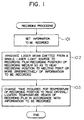
- the recording or writing process is performed through steps 101 to 103 in Fig. 1 as described later.
- the recrystallizing region will be explained below.
- the abscissa represents a laser irradiation time tp (pulse width), and the ordinate represents laser irradiation power P.
- the phase change state of the recording film consisting of an unchanging region, a recrystallizing region, an amorphousizing region, and a damaged region due to excessive heating is decided in accordance with tp and P.
- Each region basically depends on the heat temperature of the recording film.
- the boundary line has, on the longer irradiation time side, a more moderate gradient than the line with t x P - constant.
- the amorphousizing boundary line f 2 with tp: short which is rightwardly descending can be made rightwardly ascending in the region with tp: long (Fig. 3A).
- the region partitioned by the melt line and the amorphousizing boundary line causes crystallization, it provides different operations. More specifically, the crystallization below the melt line only means that crystallization is facilitated in the solid state whereas the crystallization over the melt line means that the recording film is once melted at a temperature exceeding the melting point to be its liquid state and recrystallized in the cooling process.
- the region over the melt line is referred to as recrystallizing region.
- the recrystallization depends on the ratio of the passing time t e (time required to pass the crystallization temperature region in the cooling process from the melting point) to the crystallization time ⁇ (Tn), i.e., t c / ⁇ (Tn).
- t c / ⁇ (Tn) large ( »1)
- t c / ⁇ (Tn) small (« 1)
- the film is difficult to be recrystallized since it is abruptly cooled from the liquid phase and is quenched to be amorphous.
- the first passing time factor t c ⁇ defined by the heat dissipating constant is large as the thermal capacity of the recording film is small and the thermal conduction of the neighboring material is high.
- the irradiation power is enhanced with the heat dissipating constant fixed, the temperature change per unit time is increased so that the time required to pass the crystallization temperature region is decreased. Then, the second passing time factor t c ⁇ becomes small. Moreover, if the irradiation time t c is increased, the effective thermal capacity appears to have been increased due to the thermal diffusion from the laser spot portion during irradiation. Then, the effective heat dissipating constant becomes large and the cooling speed becomes low so that the third passing time factor t c ⁇ becomes large.
- the recrystallization state depends on which of t e a, t c ⁇ , and t c y is dominant in the ratio of the passing time t e to the crystallization time ⁇ (Tn).
- the recording film at recording positions is melted while the irradiation laser power profile is controlled to cause a phase change between the amorphous state and the recrystallization state.
- the first passing time factor t c ⁇ which is a fixed component depending on the disk composition and make dominant the second and third passing time factors t c ⁇ and t cY .
- the heat dissipating constant can be decreased and so, the first passing time factor t e a can be decreased.
- (t c ⁇ + t c ⁇ ) can be controlled using the power profile. It is assumed that the average value of (t c ⁇ + t c ⁇ ) in a controllable range is t a , and a recording film having the crystallization time ⁇ (Tn) equal to t a . Then, the value of (t c ⁇ + t c ⁇ / ⁇ (Tn) can be varied centering 1 by changing the power profile of the irradiation laser.
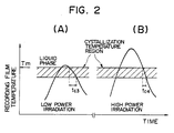
- Figs. 2A and 2B show the temperature profiles of the recording film when a metallic film with enhanced heat dissipating property is provided in thermal coupling with the recording film so as to decrease t e a.
- t c a When t c a is decreased, the thermal response speed during laser irradiation is enhanced so that the temperature profile can respond to the power profile of a laser spot itself in Gaussian distribution when the laser spot passes.
- the temperature profile is also similartothe Gaussian distribution. Specifically, temperature changes slowly around the peak of the temperature profile and changes rapidly around the middle thereof. When low power is irradiated, as seen from Fig.
- the temperature of the recording film passes the crystallization temperature region where temperature change is moderate, so that the passing time t c 3 during low power irradiation becomes long. Then, the recording film is cooled slowly from the liquid phase and recrystallized.
- the temperature of the recording film passes the crystallization temperature region where temperature change is abrupt, so that the passing time t c 4 is short during high power irradiation. Then, the recording film is cooled quickly from the liquid phase and is made amorphous.
- the boundary partitioning the recrystallizing region and the amorphousizing region is a rightwardly ascending line.
- the irradiation power profile to increase a change of to and also adjusting thermal diffusion to restrict t c ⁇ so as to make t c ⁇ more dominant, the gradient of the boundary line between the recrystallizing region and the amorphousizing region can be made moderate.
- the gradient of the boundary line can be made abrupt.
- a recording medium with a recrystallizing region and the adjusted gradient of the boundary between it and an amorphousizing region can be provided. Then, if the single beam overwrite is performed between the recrystallizing region and the amorphousizing region, all the operating points are located at the temperatures exceeding the melting point. Thus, the recording film of the recording position is melted and once expeniences the liquid phase. Therefore, the difference of crystallization rate among the previous state of the operating points, which is a cause of incomplete erasing in the overwrite, can be removed. Through the melting, the recording film of the recording position is subjected to perfect erasing, thereby providing a high erasing ratio or high erasing capability.
- the irradiation time tp is set as follows where
- the boundary line of an amorphousizing region is indicated by a reference numeral 1, that of a crystallizing region is indicated by a numeral 2, that of a damaged region is indicated by a numeral 3, and a melt line is indicated by a numeral 4.
- the solid line is a graph when the initial state is in a crystalline state, and the broken line is a graph when the initial state is in an amorphous state.
- the reflection coefficient starting from the crystalline state starts to increase at the irradiation power of 9 mW and is saturated at that of 14 mW.
- the reflection coefficient starting from the amorphous state starts to decrease at an irradiation power of 6 mW, becomes the reflection coefficient corresponding to a crystalline state at an irradiation power of 9 mW, starts to increase there again, and is saturated at an irradiation power of 14 mW or more, thus providing a reflection coefficient corresponding to the amorphous state again.
- the intermediate level between the reflection coefficients corresponding to the crystalline state and the amorphous state is a boundary of phase change
- 7 mW is crystallizing power
- 12 mW is amorphousizing power
- 9 mW is melting power P M .
- Fig. 4A shows, in comparison between embodiments (examples) of the present invention and examples of the prior art, characteristics or CNR (ratio of carrier signal level to noise) and erasing ratio when single beam overwrite is performed between the frequency of 2 MHz and 3 MHz; the erasing ratio means what amount of 2 MHz signal is erased when 3 MHz signal is written on 2 MHz signal.
- CNR ratio of carrier signal level to noise
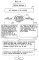
- Fig. 5 shows steps for implementing this operation. Accordingly, a high CNR of 49 dB can be realized and also a high erasing ratio of 41 dB, which is due to the fact that the operation point is set at a temperature or the melting point or more, can be realized.
- Example 2 will be explained.
- the single beam overwrite is performed between the recrystallizing region and the amorphousizing region which is not located above the recrystallizing region.
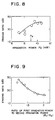
- Fig. 6A shows the same temperature profile with the same laser power and irradiation time as that of Example 1 shown in Fig. 2A.
- the irradiation time is decreased and the power is increased so that the maximum temperature of the recording film reaches the same temperature as in Fig. 6A.
- the temperature of the recording film abruptly decreases since due to the short irradiation time, laser irradiation stops before the laser spot passes the recording position.
- the temperature profile of Fig. 6A accords with the passing of the laser beam and exhibits a gradual temperature fall under the influence of the power distribution of the laser beam spot.
- the temperature profile of Fig. 6A accords with the passing of the laser beam and exhibits a gradual temperature fall under the influence of the power distribution of the laser beam spot.
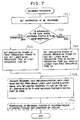
- Fig. 28 shows steps 701 to 705 for recording information by this recording technique (step 706 is optional).
- Example 2 the CNR of 52 dB and the erasing ratio of 40 dB can be realized. Since the operating points are set for both amorphousizing and crystallizing modes at the temperature of the melting point or more in Example 1, such a high erasing ratio can be obtained. Further, since the recording in the amorphousizing mode is carried out in a shorter irradiation time than Example 1 to increase the cooling speed thereby to facilitate the amorphousizing so as to increase change of the reflection coefficient, such a high CNR can be obtained.
- Example 1 the time of the laser beam spot passing the recording position is 0.2 ⁇ s whereas the recording laser irradiation time with the signal at 2 MHz is 0.25 ⁇ s (duty factor : 50%).
- Example 2 it will be understood that pulses having a pulse width of 0.05 ⁇ s which is shorter than the passing time 0.2 ⁇ s of the beam spot.
- the recording operation in the crystallizing mode is at the temperature lower than the melting point so that the previous history cannot be removed and so a high CNR of 52 dB can be obtained but the erasing ratio is as low as 27 dB.
- the conventional Example 2 is directed to the case where the recording in the amorphousizing mode is carried out with short irradiation time tp as in Example 2.
- more abrupt cooling facilitates the amorphousizing so that the CNR is enhanced to 54 dB whereas the erasing ratio is greatly lowered to 20 dB.
- the conventional examples in which there is a great difference in the crystallizing rate between the amorphous portion and the crystal portion in the previous history and the previous history cannot be removed, provides a high CNR but also a decreased erasing ratio.
- Examples 1 and 2 of the present invention provide substantially equal erasing ratios and have an advantage of providing high erasing ratio irrespectively of the irradiation time tp.
- the first erasing power P 1 for amorphousizing must be increased to a value as high a 16 mW for the recording in the amorphousizing mode with a short irradiation time whereas the irradiation power P 3 for crystallizing used is as low as 8 mW. Then, the ratio P 1 /P 3 is large so that the width of the heating region with an equal laser power density is greatly shifted between the recording portion in the amorphousizing mode and the recording portion in the crystallizing mode and winds on a recording track. This winding also promotes incomplete erasure.
- a recrystallizing region is formed as an operating property to place operating points in the crystallizing mode therein.
- the recrystallizing region is set on the side of higher power than only a crystallizing region so that the ratio P 1 /P 2 can be decreased and so, incomplete erasure can be restrained.
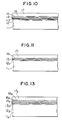
- Fig. 10 shows the arrangement of an optical disk in accordance with the above examples of the present invention.
- the optical disk is composed of an aluminium nitride film (AfNfilm) 12, a recording film 13, another Af Nfilm 14, an gold (Au) film 15, a further AfNfilm 16, and an ultraviolet ray setting resin film 17 stacked successively on a substrate 11 in the following arrangement.
- the AfN film 12 having a thickness of 70 nm is formed as an interference film on the substrate with a tracking guide, of glass, having a diameter of 130 mm through the sputtering technique.
- the recording film 13, made of a tertiary system of indium-antimony-tellurium (In-Sb-Te), having a thickness of 50 nm is formed thereon through the sputtering technique.
- AnotherAf N film 14 having a thickness of 70 nm is formed thereon through the sputtering. Further, the Au film 15 having a thickness of 100 nm is thereon formed as a reflection film through through the sputtering technique. Finally, the further AlN film 16 as a protection film having a thickness of 100 nm and the ultraviolet ray setting resin film 17 having a thickness of 10 ⁇ m are spin-coated thereon.
- a tantalum pentaoxide (Ta 2 0 5 ) film 12 2 having a thickness of 70 nm is formed as an interference/thermal protection film on an injection-molded replica substrate 11 1 formed of polycarbonate and having tracking guide; a recording film 13 1 , made of a tertiary system of antimony-selenium-bismuth (Sb-Se-Bi), having a thickness of 90 nm is formed thereon; and another Ta 2 0 5 film 16 1 having a thickness as a protection film is formed thereon.
- Sb-Se-Bi antimony-selenium-bismuth
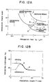
- Fig. 12A shows partition of the phase change regions in the above optical disk.
- the thermal protection film is made of Ta 2 0 5 which has lower thermal conductivity than Af N
- the recording film is made of Sb-Se-Bi which requires a longer crystallizing time than In-Sb-Te. Therefore, a recrystallizing region is shifted on the side of longer laser irradiation time as compared with Fig. 3A, and the recrystallizing region above which an amorphousizing region is located can be formed in the range of an irradiation time of 0.3 ⁇ s - 2 ⁇ s.
- Fig. 12B shows a relation between laser irradiation power P and a reflection coefficient at an irradiation time of 1 ⁇ s (linear speed : 1 m/s).
- the solid line indicates the case where the initial state is crystalline and the broken line indicates the case where the initial state is amorphous.
- the reflection coefficient in the amorphous state and the crystalline state in this disk is reverse to the case of Fig. 3B, namely, the crystalline state has a larger reflection coefficient.
- This is decided by the reflective index, the absorptive coefficient and the thickness of the Sb-Se-Bi film and the wavelength ( 830 nm) of the used laser, and he present invention does not depend on the value of the reflection coefficient in the amorphous and crystalline states.
- the crystallizing power is 6 mW
- the melt power is 10 mW
- the amorphousizing power is 13 mW.
- the overwrite is repeated at frequencies of 0.5 MHz and 0.7 MHz.
- this example permits recording to be performed with the frequency and the pulse width (and so irradiation time t) being changed, thereby providing a high CNR and a high erasing ratio at a low linear speed.
- Fig. 13 shows the arrangement of an optical disk which is adapted to the use in which the linear speed varies in the range of 5 m/s to 12 m/s in the inner and outer peripheries in a 5.25 inch disk in a CAV (angular speed: constant) system for data storage.
- CAV angular speed: constant
- a silicon nitride (SiN) film 12 2 having a thickness of 70 nm is formed as an interference film on a glass substrate 11 2 having a tracking guide, a tertiary InSbTe system film 13 2 having a thickness of 60 nm is formed as a recording film thereon; another SiN film 14 2 having a thickness of 150 nm is formed thereon; a copper (Cu) film 15 2 having a thickness of 80 nm is formed as a reflection film thereon; and a further SiN film 16 having a thickness of 100 nm is formed thereon. These films are formed through the sputtering technique. Finally, an ultraviolet ray setting resin film 17 2 having a thickness of 100 ⁇ m is spin-coated thereon.
- the arrangement of the disk shown in Fig. 13 is basically the same as the disk (Fig. 10) used in Examples 1 and 2. However, the former is different from the latter in the following points.
- SiN which has substantially the same reflactive index as Af N but, lower thermal conductivity than Af N is used to advance the start of the recrystallization.
- Fig. 14A shows partition of phase change regions in the above disk.
- the amorphousizing region boundary line exhibits a rightwardly gradually ascending curve on the side of longer irradiation time than 0.08 ⁇ s.
- Reference numeral 4 denotes a melt line
- 5 denotes a recrystallizing region
- 6 denotes an amorphousizing region.
- the amorphousizing region is located above the recrystallizing region in a wide range of irradiation time of 0.08 ⁇ s - 1 ⁇ s.
- Fig. 14B shows a relation between irradiation power and a reflection coefficient with an irradiation time of 0.1 ⁇ s (corresponding to a laser spot diameter of 1 ⁇ m, a rotation number of 1800 rpm and a radius of 60 mm).
- Fig. 14C shows a relation between irradiation power and a reflection coefficient with a irradiation time of 0.2 ⁇ s.
- a and Care directed to the case measured at the operating point in the crystallizing mode and B and D are directed to the case measured at the operating point in the amorphousizing mode.
- the solid line indicates the case where the initial state is crystalline and the broken line indicates the case where the initial state is amorphous.
- Fig. 14C shows a relation between irradiation power and a reflection coefficient with a irradiation time of 0.2 ⁇ s.
- the crystallizing power is 8 mW
- the melt power is 10 mW
- the amorphousizing power is 12 mW
- the crystallizing power is 5 mW
- the melt power is 8 mW
- the amorphousizing power is 14 mW.
- the overwrite is repeated at frequencies of 2.75 MHz and 3.75 MHz.
- a CNR of 48 dB and an erasing ratio of 40 dB are obtained in the inner periphery
- a CNR of 50 dB and an erasing ratio of 37 dB are obtained in the outer periphery.
- the phase state at the recording film of the recording position can be controlled.
- the flow chart of recording information in this case is illustrated by steps 1501 to 1508 in Fig. 15.
- the temperature profile of the recording film in this case is also shown in Figs. 16A and 16B.
- the maximum arrival temperature is higher than the case where the irradiation time is short since higher energy is provided with the same power. Since the maximum temperature is set higher in the cooling process, the profile passing the crystallization temperature can be set in a second moderate change region in the temperature profile.
- the temperature profile experiences a first moderate change in the neighborhood of the peak thereof, an abrupt change in the way and the above second moderate change in the low temperature region again. Further, the slope of the temperature profile is more moderate than the case of the short irradiation time due to the lengthened irradiation time.
- the profile passing the crystallization temperature region is a steep portion since the maximum arrival temperature is relatively low. Also, the profile slope itself is steep due to the shortened irradiation time.
- the passing time t e 5 through the crystallization temperature region in the case where the irradiation time is long can be lengthened, whereas the passing time t c 6 through the crystallization temperature region in the case where the irradiation time is short can be shortened.
- the phase state of the recording position can be controlled to be amorphous or crystalline, and the recording position, after once heated at a temperature higher than the melting point, can be overwritten. Then, the operating point of the crystallization corresponds to E point in Figs. 14A to 14C, and that of the amorphousizing corresponds to F point therein.
- the basic idea of the present invention as shown in the flow chart of Fig. 1, to once heat the recording film at a recording position to the temperature of the melting point or more, and thereafter change the time required for the temperature of the heated recording position to pass through the crystallization temperature region in accordance with whether information to be recorded is amorphous or crystalline.
- the previous history can be removed, by melting the recording film thus realizing the overwrite with a high erasing ratio.
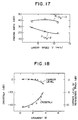
- Fig. 17 shows a relation between the linear speed V and the erasing ratio.
- the present invention has an advantage of providing a high erasing ratio irrespectively of the linear speed.
- the irradiation power (more precisely irradiation power linear density) is larger in the inner periphery with a lower linear speed so that spread of heat in the direction of track width is larger in the inner periphery, which gives rise to problems of increase of crosstalk and erasure of neighboring tracks.
- Fig. 18 shows relations between the gradient M of the amorphousizing boundary line, the crosstalk due to expansion of the recording pits in the inner periphery and the erasing ratio in the neighboring tracks (represented by reduction of the carrier level therein) when the gradient of the amorphousizing boundary line is varied by varying the film thickness of the reflection film of Au or Cu in the disk of Fig. 10 or Fig. 13, or using an aluminum (Af) film having thermal conductivity than Au and Cu.
- P 1 and P 2 at the respective operating points are optimized so as to provide a high CNR and a high erasing ratio.
- the crosstalk and the erasure of the neighboring track can be restrained so that the single beam overwrite can be performed for an optical disk in which the linear speed varies doubly.
- tp 2 /tp, ⁇ 2 it is preferable to set tp 2 /tp 1 -- 3 with a 1.5 times margin for operating shake.
- Fig. 19 is a block diagram of the arrangement of one embodiment of an optical information recording device.
- 191 is a laser light source for irradiating a laser beam spot to a recording position in the recording film of a recording medium 192.
- Reference numeral 193 denotes an optical pick-up including the laser light source.
- Reference numeral 194 denotes a laser driving circuit for driving the laser light source 191 in the optical pick-up 193
- reference numeral 195 denotes a moving mechanism for relatively moving the recording medium 192 and the optical pick-up 193.
- Reference numeral 196 denotes a system control circuit for controlling the moving mechanism 195 and also controlling the laser driving circuit 194 on the basis of predetermined information.
- the system control circuit 196 incorporates a passing time control circuit 197 for controlling the laser driving circuit 194 so that the recording position in the recording medium 192 is heated at the melting point or more regardless of the information to be recorded and controlling the time required for the recording position to pass the crystallization temperature region of the recording medium 192 after the recording position has been heated at the melting point or more, in accordance with information to be recorded.
- the system control circuit 196 first sends a moving control signal to the moving mechanism 195 to shift the recording medium 192 relatively for the optical pick-up 193.
- the system control circuit 196 sends a laser driving control signal corresponding to the information to be recorded to the laser driving circuit 194 with reference to the passing time control circuit 197.
- the system control circuit 196 sends to the laser driving circuit 194 a control signal for heating the recording position to apply the laser beam to the melting point or more to shorten the passing time required to pass the crystallization temperature region.
- the laser driving circuit 194 sends a driving signal to the laser light source 191.
- the laser light source 191 irradiates the laser beam to the recording medium 192.
- the amorphousizing of the recording position can be implemented, for example, by irradiating the laser with high power and with a narrow pulse width so as to shorten the irradiation time, thereby to shorten the time required to pass the crystallization temperature region of the recording medium.
- the laser light source 191 is driven so as to heat the recording position to the melting point or more and also to irradiate it with the laser with low power and a wide pulse width increasing the irradiation time with reference to the passing time control circuit 197.
- the passing time required to pass the crystallization temperature region can be increased, thus crystallizing the recording film of the recording position.
- the recording film of the recording position is heated to the melting point or more to remove the previous history at the time of overwrite by melting the recording film of overwriting position, thereby providing an optical information recording apparatus with a high erasing ratio and few errors.
- the passing time control circuit 197 may be placed outside the system control circuit 196.
- Fig. 20A shows the arrangement of an optical information recording/reproducing apparatus in accordance with one embodiment of the present invention.
- This apparatus comprises an optical pick-up 221 irradiating a laser beam 231 to an optical disk 227 having a tracking guide, an optical pick-up position control circuit 222, a received light signal processing circuit 223, a semiconductor laser driving circuit 224, a disk rotating motor 225, a turn table 226, a recording condition discriminating circuit 228 for an optical disk recording film, a system control circuit 229, and a group of external input/output terminals.
- the optical disk 227 is formed of an A$N film 271, an In-Sb-Te system thin film 272, anotherAf N film 273, an Au film 274, a fur- therAfN film 275, and an ultraviolet ray setting resin film 276 successively stacked on a glass substrate 270.
- the AfN film 271 having a thickness of 70 nm on the glass substrate 270, the In-Sb-Te system thin film 272 having a thickness of 50 nm is formed as a recording film thereon; another Af N film 273 having a thickness of 70 nm is formed thereon; the Au film 274 having a thickness of 100 nm is formed thereon: and the further AfN film 275 having a thickness of 100 nm is formed as a protection film thereon.
- These films are formed through the sputtering technique.
- the ultraviolet ray setting resin film 276 having a thickness of 10 ⁇ m is spin-coated as a protection film thereon.
- the optical disk 227 is placed on the turntable 226, which is rotated by the motor 225 so as to rotate the optical disk 227.
- the on-off control of rotation is performed through the system control circuit 229 from the external input/output terminals 230.
- the optical disk 227 is irradiated with the laser beam 231 from the optical pick-up 221.
- a reflection light of the laser beam 231 returns to the optical pick-up 221.
- the reflection light is sent to the received light signal processing circuit 223 to provide a signal indicating the height of the optical pick-up and a signal indicating a deviation or difference of the pick-up on a track thereof.
- the optical pick-up position control circuit 222 uses these signals to provide focusing and tracking of the optical pick-up for the optical disk.
- the on-off control of the focusing and tracking is performed through the system control circuit 229 from the external input/output terminals 230.
- optical pick-up 221 can be set every moment at optical irradiation power by the system control circuit 229 through the semiconductor driving circuit 224, which permits overwrite by a single beam.
- a control 232 track provided in the inner periphery or outer periphery of the optical disk 227 is the data record 233 of the melting point of the recording film in the optical disk227, or the recording condition (irradiation power, passing time or irradiation time required for amorphousizing or crystallizing, etc.) required for heating the recording position to the melting point or more.
- This data record 233 is sent to the recording condition discrimination circuit 228 through the optical pick-up 221 and the received light processing circuit 223.
- the discrimination result is sent to the semiconductor laser driving circuit 224 through the system control circuit 229.
- the first irradiation power P 1 and the second irradiation power P 2 at the time of single beam overwrite can be set at the power for heating the recording film of the overwriting position to the melting point or more.
- reproduced information only passes the discrimination circuit 228 and is sent to the external input/output terminals 230 through the system control circuit 229.
- the recording condition discrimination circuit 228 may decode the data record 233 on the recording condition so as to permit the overwrite at the melting point or more; otherwise may obtain differences in the reflection coefficient during actual laser irradiation using a dummy track to provide the melt power P M for heating to the melting point from the difference.
- the recording condition data (8 bits) includes, for example, a 8-bit start code indicative of the start of the recording condition data, 32-bit data indicative of the melting point of the recording film, 32-bit data indicative of the passing data for amorphousizing after molten, 32-bit data indicative of the passing time for crystallization after molten, and 8-bit end code indicative of the end of the recording condition data.
- the recording condition data includes a 8-bit start code, 32-bit data irradiation power data and 32-bit irradiation time data for heating the recording film to the melting point or more for amorphousizing, 32-bit irradiation power data and irradiation time data indicative of the irradiation time for heating the recording film to the melting point or more for crystallization, and 8-bit end code.
- the history of the information previously recorded can be removed by once heating the recording film to the melting point to be molten in both amorphousizing overwrite mode and crystallizing overwrite mode, thus providing a high erasing ratio. Also by setting the crystallization time of the recording film at a longer time than the laser irradiation time, a high CNR can obtained using a single beam.
- a method and apparatus for recording optical information and a recording medium used therefor which permit the overwrite using a single beam with a high erasing ratio.
Claims (6)
Applications Claiming Priority (2)
| Application Number | Priority Date | Filing Date | Title |
|---|---|---|---|
| JP63139305A JP2680039B2 (ja) | 1988-06-08 | 1988-06-08 | 光情報記録再生方法及び記録再生装置 |
| JP139305/88 | 1988-06-08 |
Publications (3)
| Publication Number | Publication Date |
|---|---|
| EP0345752A2 EP0345752A2 (de) | 1989-12-13 |
| EP0345752A3 EP0345752A3 (de) | 1991-10-09 |
| EP0345752B1 true EP0345752B1 (de) | 1994-11-02 |
Family
ID=15242196
Family Applications (1)
| Application Number | Title | Priority Date | Filing Date |
|---|---|---|---|
| EP89110279A Expired - Lifetime EP0345752B1 (de) | 1988-06-08 | 1989-06-07 | Optische Informationsaufzeichnungsmethode und Gerät und Aufzeichnungsmedium dafür |
Country Status (5)
| Country | Link |
|---|---|
| US (1) | US5107482A (de) |
| EP (1) | EP0345752B1 (de) |
| JP (1) | JP2680039B2 (de) |
| KR (1) | KR920010017B1 (de) |
| DE (1) | DE68919131T2 (de) |
Cited By (1)
| Publication number | Priority date | Publication date | Assignee | Title |
|---|---|---|---|---|
| US8673745B2 (en) | 2002-03-12 | 2014-03-18 | Hamamatsu Photonics K.K. | Method of cutting object to be processed |
Families Citing this family (25)
| Publication number | Priority date | Publication date | Assignee | Title |
|---|---|---|---|---|
| JP2804130B2 (ja) * | 1989-12-06 | 1998-09-24 | 株式会社日立製作所 | 情報処理装置 |
| US5194363A (en) * | 1990-04-27 | 1993-03-16 | Matsushita Electric Industrial Co., Ltd. | Optical recording medium and production process for the medium |
| FR2661769B1 (fr) * | 1990-05-02 | 1995-04-21 | Thomson Csf | Systeme d'enregistrement optique de donnees sur disque, et procedes de lecture et ecriture correspondants. |
| DE4114234A1 (de) * | 1990-05-16 | 1991-11-21 | Mitsubishi Electric Corp | Optisches aufnahme- und speichermedium und optische aufnahmevorrichtung |
| JPH04245565A (ja) * | 1991-01-31 | 1992-09-02 | Toshiba Corp | 画像検索装置 |
| JP3076412B2 (ja) * | 1991-07-24 | 2000-08-14 | 松下電器産業株式会社 | 光学的情報記録媒体および光学的情報記録再生方法 |
| US5367514A (en) * | 1991-11-26 | 1994-11-22 | Fuji Xerox Co., Ltd. | Phase change optical recording device and method employing a laser beam with differently energized pulse portions |
| US5796708A (en) * | 1993-06-11 | 1998-08-18 | Kabushiki Kaisha Toshiba | Optical recording medium and recording system |
| JP3231533B2 (ja) * | 1994-01-31 | 2001-11-26 | 株式会社日立製作所 | 光学的情報記録方法 |
| JP2806274B2 (ja) * | 1994-10-19 | 1998-09-30 | 日本電気株式会社 | 光学情報記録媒体 |
| JPH10214424A (ja) * | 1997-01-29 | 1998-08-11 | Ekisupaato Magnetics Kk | Cd−rの消去方法及び装置 |
| JP2001281345A (ja) * | 2000-03-31 | 2001-10-10 | Fuji Photo Film Co Ltd | エネルギー線検出装置およびその温度調整方法 |
| JP4659300B2 (ja) | 2000-09-13 | 2011-03-30 | 浜松ホトニクス株式会社 | レーザ加工方法及び半導体チップの製造方法 |
| JP4491985B2 (ja) * | 2001-03-28 | 2010-06-30 | Tdk株式会社 | 光記録方法 |
| US20030128646A1 (en) * | 2002-01-09 | 2003-07-10 | Peter Nangle | Asymmetrical programming mechanism for non-volatile memory |
| ATE534142T1 (de) | 2002-03-12 | 2011-12-15 | Hamamatsu Photonics Kk | Verfahren zum auftrennen eines substrats |
| TWI326626B (en) | 2002-03-12 | 2010-07-01 | Hamamatsu Photonics Kk | Laser processing method |
| TWI520269B (zh) | 2002-12-03 | 2016-02-01 | Hamamatsu Photonics Kk | Cutting method of semiconductor substrate |
| FR2852250B1 (fr) | 2003-03-11 | 2009-07-24 | Jean Luc Jouvin | Fourreau de protection pour canule, un ensemble d'injection comportant un tel fourreau et aiguille equipee d'un tel fourreau |
| CN1758985A (zh) | 2003-03-12 | 2006-04-12 | 浜松光子学株式会社 | 激光加工方法 |
| TWI238159B (en) * | 2003-09-23 | 2005-08-21 | Ind Tech Res Inst | Indolestyryl compounds and use thereof for a high density recording medium and method for producing the same |
| US8168920B2 (en) * | 2007-09-11 | 2012-05-01 | Shibuya Kogyo Co., Ltd. | Bonding device |
| US7768729B2 (en) * | 2008-01-31 | 2010-08-03 | Hitachi Global Storage Technologies Netherlands B.V. | Method, system, and computer program product for estimating adjacent track erasure risk by determining erase band width growth rates |
| WO2019174015A1 (zh) * | 2018-03-15 | 2019-09-19 | Oppo广东移动通信有限公司 | 处理数据的方法、接入网设备和核心网设备 |
| CN111508533B (zh) * | 2019-01-30 | 2022-08-30 | 中国科学院上海高等研究院 | 基于纳米光刻光盘及其物理存储介质结构和写入读出方法 |
Family Cites Families (14)
| Publication number | Priority date | Publication date | Assignee | Title |
|---|---|---|---|---|
| JPS56145530A (en) * | 1980-04-15 | 1981-11-12 | Matsushita Electric Ind Co Ltd | Optical information recording and erasing method |
| JPS5960742A (ja) * | 1982-09-30 | 1984-04-06 | Fujitsu Ltd | 光デイスクの記録再生制御方法 |
| JPS60231928A (ja) * | 1984-04-27 | 1985-11-18 | Matsushita Electric Ind Co Ltd | 光学情報記録消去方法 |
| JPS618739A (ja) * | 1984-06-20 | 1986-01-16 | Matsushita Electric Ind Co Ltd | 消去可能な光学的記録再生装置 |
| DE3601265A1 (de) * | 1985-01-18 | 1986-07-24 | Kabushiki Kaisha Toshiba, Kawasaki, Kanagawa | Optisches system fuer informationsaufzeichnung |
| JPH0619835B2 (ja) * | 1985-05-22 | 1994-03-16 | 株式会社ニコン | 情報記録装置 |
| US4787077A (en) * | 1985-08-15 | 1988-11-22 | International Business Machines Corporation | Process for optically storing information using materials having a single phase in both the crystalline state and the amorphous state |
| JPH0777025B2 (ja) * | 1985-10-16 | 1995-08-16 | 株式会社日立製作所 | 光学的記録再生装置 |
| JPH0721876B2 (ja) * | 1986-08-28 | 1995-03-08 | 松下電器産業株式会社 | 光情報記録担体 |
| CA1320268C (en) * | 1986-09-10 | 1993-07-13 | Wataru Sakagami | Information record medium having an area for recording information indicating logical erasure of data and method for recording information on the same |
| JPH0827950B2 (ja) * | 1986-10-20 | 1996-03-21 | オリンパス光学工業株式会社 | 光学的情報記録再生装置のレ−ザコントロ−ル回路 |
| US4939717A (en) * | 1986-10-31 | 1990-07-03 | Matsushita Electric Industrial Co., Ltd. | Method and apparatus for erasing and recording information using three power levels |
| US4876667A (en) * | 1987-06-22 | 1989-10-24 | Energy Conversion Devices, Inc. | Data storage device having a phase change memory medium reversible by direct overwrite |
| US4924436A (en) * | 1987-06-22 | 1990-05-08 | Energy Conversion Devices, Inc. | Data storage device having a phase change memory medium reversible by direct overwrite and method of direct overwrite |
-
1988
- 1988-06-08 JP JP63139305A patent/JP2680039B2/ja not_active Expired - Fee Related
-
1989
- 1989-06-05 KR KR1019890007699A patent/KR920010017B1/ko not_active IP Right Cessation
- 1989-06-07 EP EP89110279A patent/EP0345752B1/de not_active Expired - Lifetime
- 1989-06-07 US US07/362,699 patent/US5107482A/en not_active Expired - Fee Related
- 1989-06-07 DE DE68919131T patent/DE68919131T2/de not_active Expired - Fee Related
Cited By (1)
| Publication number | Priority date | Publication date | Assignee | Title |
|---|---|---|---|---|
| US8673745B2 (en) | 2002-03-12 | 2014-03-18 | Hamamatsu Photonics K.K. | Method of cutting object to be processed |
Also Published As
| Publication number | Publication date |
|---|---|
| DE68919131T2 (de) | 1995-06-14 |
| EP0345752A3 (de) | 1991-10-09 |
| KR920010017B1 (ko) | 1992-11-10 |
| US5107482A (en) | 1992-04-21 |
| JPH01311422A (ja) | 1989-12-15 |
| JP2680039B2 (ja) | 1997-11-19 |
| DE68919131D1 (de) | 1994-12-08 |
| KR900000859A (ko) | 1990-01-31 |
| EP0345752A2 (de) | 1989-12-13 |
Similar Documents
| Publication | Publication Date | Title |
|---|---|---|
| EP0345752B1 (de) | Optische Informationsaufzeichnungsmethode und Gerät und Aufzeichnungsmedium dafür | |
| EP0669611B1 (de) | Optisches Informationsaufzeichnungsverfahren und Aufzeichnungsgerät | |
| US5412626A (en) | Method of recording optical information with selective correction in pulse waveform and a recording system therefor | |
| EP0549562B1 (de) | Verfahren und Vorrichtung zur Aufzeichnung und Wiedergabe von Information | |
| JP3171103B2 (ja) | 光記録方法および光記録媒体 | |
| KR100551917B1 (ko) | 광기록 방법, 광기록장치 및 광기록매체 | |
| EP1128365A1 (de) | Verfahren zur aufzeichnung und wiedergabe von mehrwertigen digitalen signalen und mehrwertaufzeichnungsmedium des phasenwechsel-typs | |
| US5038338A (en) | Recording waveform for mark-length modulation optical recording | |
| JP2707774B2 (ja) | 光学情報の記録方法および記録装置 | |
| US6396792B1 (en) | Recording method of a phase change optical recording medium and recording apparatus | |
| JP2719130B2 (ja) | 情報の記録・再生および書き換え方法とその装置 | |
| US5257256A (en) | Recording waveform for mark-length modulation optical recording | |
| US6438085B1 (en) | Optical recording method | |
| US5084857A (en) | Information recording method using a modulated recording beam at high, intermediate and low power levels | |
| JP2827545B2 (ja) | 光学情報の記録方法 | |
| EP1612779B1 (de) | Verfahren zur Aufzeichnung von Daten auf optischen Aufzeichnungsmedien, und optisches Aufzeichnungsgerät | |
| EP1473712A1 (de) | Optisches aufzeichnungs medium und verfahren zum aufzeichnen von informationen auf einem optischen aufzeichnungsmedium | |
| WO2003028021A1 (fr) | Support d'enregistrement optique et systeme d'enregistrement associe | |
| JP3455521B2 (ja) | 光記録方法 | |
| JP3076083B2 (ja) | 光ディスク初期化方法及び光ディスク記録方法 | |
| JP2773662B2 (ja) | 光学情報の記録装置 | |
| KR920010020B1 (ko) | 광정보 기록 매체 | |
| KR20050042785A (ko) | 기록매체의 상변화형 정보층에 마크들을 기록하는 방법 및장치 | |
| JPH08235588A (ja) | 情報の記録方法 | |
| JPH04313816A (ja) | 光学的情報記録媒体の記録消去方法および装置 |
Legal Events
| Date | Code | Title | Description |
|---|---|---|---|
| PUAI | Public reference made under article 153(3) epc to a published international application that has entered the european phase |
Free format text: ORIGINAL CODE: 0009012 |
|
| 17P | Request for examination filed |
Effective date: 19890609 |
|
| AK | Designated contracting states |
Kind code of ref document: A2 Designated state(s): DE FR GB |
|
| PUAL | Search report despatched |
Free format text: ORIGINAL CODE: 0009013 |
|
| AK | Designated contracting states |
Kind code of ref document: A3 Designated state(s): DE FR GB |
|
| 17Q | First examination report despatched |
Effective date: 19930727 |
|
| GRAA | (expected) grant |
Free format text: ORIGINAL CODE: 0009210 |
|
| AK | Designated contracting states |
Kind code of ref document: B1 Designated state(s): DE FR GB |
|
| REF | Corresponds to: |
Ref document number: 68919131 Country of ref document: DE Date of ref document: 19941208 |
|
| ET | Fr: translation filed | ||
| PLBE | No opposition filed within time limit |
Free format text: ORIGINAL CODE: 0009261 |
|
| STAA | Information on the status of an ep patent application or granted ep patent |
Free format text: STATUS: NO OPPOSITION FILED WITHIN TIME LIMIT |
|
| 26N | No opposition filed | ||
| PGFP | Annual fee paid to national office [announced via postgrant information from national office to epo] |
Ref country code: FR Payment date: 19980415 Year of fee payment: 10 |
|
| PGFP | Annual fee paid to national office [announced via postgrant information from national office to epo] |
Ref country code: GB Payment date: 19980528 Year of fee payment: 10 |
|
| PG25 | Lapsed in a contracting state [announced via postgrant information from national office to epo] |
Ref country code: GB Free format text: LAPSE BECAUSE OF NON-PAYMENT OF DUE FEES Effective date: 19990607 |
|
| PG25 | Lapsed in a contracting state [announced via postgrant information from national office to epo] |
Ref country code: FR Free format text: THE PATENT HAS BEEN ANNULLED BY A DECISION OF A NATIONAL AUTHORITY Effective date: 19990630 |
|
| PGFP | Annual fee paid to national office [announced via postgrant information from national office to epo] |
Ref country code: DE Payment date: 19990728 Year of fee payment: 11 |
|
| GBPC | Gb: european patent ceased through non-payment of renewal fee |
Effective date: 19990607 |
|
| REG | Reference to a national code |
Ref country code: FR Ref legal event code: ST |
|
| PG25 | Lapsed in a contracting state [announced via postgrant information from national office to epo] |
Ref country code: DE Free format text: LAPSE BECAUSE OF NON-PAYMENT OF DUE FEES Effective date: 20010403 |