EP0345722B1 - Capteur d'accélération - Google Patents
Capteur d'accélération Download PDFInfo
- Publication number
- EP0345722B1 EP0345722B1 EP89110207A EP89110207A EP0345722B1 EP 0345722 B1 EP0345722 B1 EP 0345722B1 EP 89110207 A EP89110207 A EP 89110207A EP 89110207 A EP89110207 A EP 89110207A EP 0345722 B1 EP0345722 B1 EP 0345722B1
- Authority
- EP
- European Patent Office
- Prior art keywords
- tilting
- acceleration
- tilting element
- axis
- center
- Prior art date
- Legal status (The legal status is an assumption and is not a legal conclusion. Google has not performed a legal analysis and makes no representation as to the accuracy of the status listed.)
- Expired - Lifetime
Links
Images


Classifications
-
- G—PHYSICS
- G01—MEASURING; TESTING
- G01P—MEASURING LINEAR OR ANGULAR SPEED, ACCELERATION, DECELERATION, OR SHOCK; INDICATING PRESENCE, ABSENCE, OR DIRECTION, OF MOVEMENT
- G01P15/00—Measuring acceleration; Measuring deceleration; Measuring shock, i.e. sudden change of acceleration
- G01P15/02—Measuring acceleration; Measuring deceleration; Measuring shock, i.e. sudden change of acceleration by making use of inertia forces using solid seismic masses
- G01P15/08—Measuring acceleration; Measuring deceleration; Measuring shock, i.e. sudden change of acceleration by making use of inertia forces using solid seismic masses with conversion into electric or magnetic values
- G01P15/0891—Measuring acceleration; Measuring deceleration; Measuring shock, i.e. sudden change of acceleration by making use of inertia forces using solid seismic masses with conversion into electric or magnetic values with indication of predetermined acceleration values
-
- G—PHYSICS
- G01—MEASURING; TESTING
- G01P—MEASURING LINEAR OR ANGULAR SPEED, ACCELERATION, DECELERATION, OR SHOCK; INDICATING PRESENCE, ABSENCE, OR DIRECTION, OF MOVEMENT
- G01P15/00—Measuring acceleration; Measuring deceleration; Measuring shock, i.e. sudden change of acceleration
- G01P15/02—Measuring acceleration; Measuring deceleration; Measuring shock, i.e. sudden change of acceleration by making use of inertia forces using solid seismic masses
- G01P15/08—Measuring acceleration; Measuring deceleration; Measuring shock, i.e. sudden change of acceleration by making use of inertia forces using solid seismic masses with conversion into electric or magnetic values
- G01P15/093—Measuring acceleration; Measuring deceleration; Measuring shock, i.e. sudden change of acceleration by making use of inertia forces using solid seismic masses with conversion into electric or magnetic values by photoelectric pick-up
Definitions
- the invention relates to an acceleration sensor with a light transmitter and a light receiver, which are arranged on an optical axis facing each other, with a rotationally symmetrical to the axis tilting part, which is arranged in a first working position coaxial to the axis and has a through-bore coaxial to the axis, so that a light beam from the light transmitter passes through the through hole to the light receiver, with holding means for holding the tilting part in the first working position with a predetermined force on a contact surface in the direction of the axis and with guide means which, in the event of acceleration acting on the tilting part, in a direction perpendicular to the axis while overcoming the predetermined force allow a limited tilting movement of the tilting part about a pivot point arranged at a distance from the axis in a second working position such that the through hole is tilted away from the path of the light beam, the Tilting part is designed in its spatial mass distribution and thus its center of gravity is positioned relative to the pivot point such that
- An acceleration sensor of the type mentioned above is known from DE-OS 35 40 947.
- Acceleration sensors of the type of interest here are e.g. used in motor vehicles to detect the exceeding of predetermined acceleration limit values and to report them in the form of electrical signals.
- This is of particular interest for occupant safety systems in motor vehicles, in which a safety function is triggered when the motor vehicle collides with an obstacle or makes unusual driving movements that deviate from the normal direction of travel as a result of a cause of danger.
- the safety function can e.g. consist in that the hazard warning lights are switched on, that the vehicle doors are unlocked centrally, that a roll bar is extended or that the fuel supply is interrupted. Sensors that are to be used for such purposes therefore only need to detect that a certain acceleration limit value has been exceeded, but this should be possible with an all-round characteristic for all accelerations that lie in a plane parallel to the roadway or a noticeable vectorial component there exhibit.
- acceleration sensors in which a seismic mass is held in a measuring system with a holding force.
- the holding force on the one hand and the seismic mass on the other hand are dimensioned such that the inertial force exerted by the seismic mass exceeds the holding force when the predetermined acceleration limit value is reached.
- the seismic mass can then measure a certain path and trigger an electrical signal in this way, which in turn can then be activated of the security system is used.
- an acceleration limit switch in which a spherical inertial body made of ferromagnetic material is held in a rest position by a permanent magnet.
- the spherical inertial body is located in a cavity of a sensor and is held in its rest position by the holding force of the permanent magnet as long as the predetermined acceleration limit value is not exceeded.
- the permanent magnet is held in the known sensor in a ferromagnetic tubular yoke, which holds the spherical inertial body with its upper free opening.
- the upper boundary surface of the cavity in which the inertial body is located is formed by a membrane which carries a switching element on its side facing away from the cavity.
- the spherical inertial body is lifted from the tubular backing pot while overcoming the holding force of the permanent magnet and rolls up in an uncontrolled manner along a guide wall which laterally encloses the cavity . If the acceleration acting on the inertial body is large enough, the inertial body strikes against the opposite membrane on its rolling path sufficiently high acceleration is deflected and the switching element is actuated.
- the known acceleration sensor thus has a distinctive all-round characteristic, as is desired for the application of interest here, but on the other hand it has several disadvantages.
- a disadvantage of the known acceleration sensor is above all that the path movement of the spherical inertial body is undefined.
- Accidental disturbances in the acceleration process can result in deviations from the desired shortest path, with the result that the spherical inertial body due to a swirl impressed on it e.g. can also describe a spiral path.
- This leads to an undesirable change in the switching threshold because in the construction of the known acceleration sensor no clear criterion can be defined for the acceleration limit value at which the switching element is just (still) triggered. Therefore, in order to prevent the known acceleration sensor from not recognizing dangerous states, the switching threshold must be lowered so that the sensor still responds in any case. On the other hand, however, this leads to undesirable false reports because, in the case of a particularly unfavorable course of acceleration, even low acceleration values which do not indicate a critical state can already lead to a triggering.
- acceleration sensor Another disadvantage of the known acceleration sensor is that vertical acceleration forces can also lead to tripping.
- Z sensitivity is Particularly disruptive in occupant safety systems of motor vehicles, because experience has shown that considerable acceleration values in the vertical direction can also occur when only the bonnet or trunk lid is slammed shut, for example, or when the motor vehicle bumps at high speed, for example a pothole, a bump or a curb runs over.
- Another disadvantage of the known acceleration sensor is that the switch contact is designed electromechanically, so that long-term suitability under the rough conditions on board a motor vehicle cannot always be guaranteed.
- the electromechanical structure of the known sensor means that the triggering spherical inertial body can trigger bouncing processes in the switch contact.
- the known acceleration sensor explained above is further developed as described in DE-PS 34 02 387.
- the mechanical contacts are supplemented by a light barrier, which is formed by a horizontally running bore which cuts the seat of the ball. If the ball sits on the bottom of its seat, the light barrier is blocked, while it is released when the ball is lifted.
- ribs are provided in the substantially conical outlet space for the ball, which ribs run along surface lines and are intended to prevent a circular movement of the ball on the conical surface of the room.
- the embodiment according to DE-PS 34 02 387 is no longer omnidirectional, because the ribs mentioned permit ball movement essentially only in four mutually perpendicular radial directions.
- the ribs provided can cause the ball to oscillate below the lower end of the rib when it is flung back and forth between the lower end points of the ribs.
- an acceleration sensor is designed in the manner described in the aforementioned DE-OS 35 40 947, numerous disadvantages of the prior art described above can be avoided.
- the acceleration sensor described there has the advantage that only a defined tilting movement of the tilting part is possible by the guide means, and essentially only in a plane perpendicular to the main axis, which coincides with the vertical axis of the motor vehicle, so that the limit value of the horizontally directed acceleration, at which the sensor should respond, can be precisely defined.
- the use of a light barrier with light transmitter, light receiver and a switchable transmission element in the form of the through hole also has the advantage here that any electromechanical switching elements are unnecessary and the aforementioned acceleration sensor remains functional even on long-term use on board a motor vehicle.
- this acceleration sensor mentioned at the outset also has disadvantages because it also has a pronounced Z sensitivity.
- the tilting part must be arranged with a certain play in the vertical axis, because otherwise a tilting movement could not be carried out.
- this means that the tilting part can overcome the adhesive force also acting in the vertical direction at least for a short time in the case of strong acceleration values in the vertical direction, and at this moment even small values of a horizontally directed acceleration are sufficient to bring the tilting part into the second working position.
- accelerations with vector components always occur in all spatial directions, for example when a motor vehicle hits a curb and thereby simultaneously in the horizontal direction is braked and sometimes accelerated downwards in the vertical direction.
- this acceleration sensor known from DE-OS 35 40 947 it is provided to set the center of gravity so that the tilting acceleration can be varied between 0.4 g and 4 g, ie that the ratio of the tear-off acceleration in the z direction, namely 1 g , can be between 2.5 and 0.25 for tilting acceleration.
- the range of the acceleration ratio is limited, because with the known acceleration sensor only the force of gravity acts in the z-direction, that is to say the break-off acceleration is always 1 g.
- the position of the center of gravity of the tilting part on the axis has no influence on the acceleration value in the direction of the axis leading to the Lifting the tilting part in the direction of the axis is also required.
- the position of the center of gravity on the axis has a significant influence on the tilting moment which is required for tilting the tilting part, because the position of the center of gravity on the axis defines the lever arm around which the seismic mass of the tilting part acts relative to the pivot point.
- the tilting part stands on the contact surface with a narrow circular ring surface, which is held on its circumference, by means of of an insert part which tightly encloses the circumference of the tilting part at the bottom and opens conically upwards, so that the tilting part can tilt away sideways in this conical opening.
- the tilting behavior at the time of response is not adequately defined, because the tilting part also initially only stands up in points on the contact surface, namely at a point on the periphery in the transition from a central, flat contact area to the radially opening annular gap.
- the invention is therefore based on the object of developing a sensor of the type mentioned in such a way that its Z sensitivity is reduced even further and a precisely defined switching behavior and thus a safe and reliable triggering of the sensor is achieved, so that false tripping can be reduced even further .
- the circumferential edge of the radially projecting collar has a vertical distance from the contact surface, and that the tilting part consists of a ferromagnetic material and the holding means have a magnet with axial magnetization, on which the tilting part in the first working position sits on.
- the known measure of the magnetic holder has the advantage that the vertical holding force can be set within wide limits, so that the acceleration in the z-direction is not limited by natural gravity.
- the tilting part is provided with an approximately cylindrical head which merges into the radially projecting collar at the bottom, and in which a recess is also provided on the underside of the tilting part, it is preferably provided that the head is tapered below the center of gravity.
- This measure has the advantage that the desired increase in the center of gravity in its position relative to the fulcrum can be brought about by the fact that the recess is formed far up into the tilt part.
- the dimensioning of the recess in such a way that it extends to the axial position of the center of gravity itself has the advantage that this is an optimum of the center of gravity with a limited overall height of the tilting part. If the turn is too far up Continued, the mass of the tilting part above the indentation becomes smaller and smaller in relation to the mass at the foot of the tilting part and on the boundary walls of the indentation, so that finally, with further enlargement of the indentation, the center of gravity reverses again and the center of gravity lowers downwards .
- the proposed measures achieve an optimum here.
- the collar is provided with a circumferential cavity.
- This measure also has the advantage that the mass fraction at the foot of the tilting part is further reduced in order to further increase the center of gravity in the axial direction.
- a non-magnetic washer of a predetermined thickness is arranged between the tilting part and the magnet.
- This measure has the advantage that, on the one hand, a flat contact surface for the foot of the tilting part can be produced by the provision of the washer.
- Conventional magnets of the type of interest here, in particular ferrites have the property that their surface is relatively rough, so that the adhesive behavior of the tilting part on the magnet cannot be set exactly reproducibly, because this adhesive behavior depends on the exact position at which the Tilting part sits on the non-flat surface of the ferrite, for example.
- the provision of a non-magnetic washer between the tilting part and the magnet has the further advantage that the thicker the washer, the less critical the dependence of the adhesive force on the thickness of the washer.
- the absolute amount of the adhesive force is indeed reduced in this way, but this can be compensated for with the sizes of the magnets of interest here by selecting the magnet accordingly.
- a relatively large air gap, which is formed by the non-magnetic washer, has the advantage for the reasons mentioned that manufacturing fluctuations in the thickness of the washer are not critical.
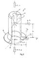
- 10 designates an acceleration sensor as it is used for passive occupant safety systems in motor vehicles.
- a coordinate system 11 describes the installation position of the acceleration sensor 10.
- the acceleration sensor 10 is arranged with its main axis in the direction of the z-axis of the coordinate system 11, which corresponds to the vertical.
- the acceleration sensor 10 is intended to serve to detect and report acceleration limit values, the essential components of which in the horizontal plane, i.e. lie in the x / y plane of the coordinate system 11.
- the acceleration sensor 10 has a cap 15, a holding part 16 and a base 17, these components preferably being made of injection molded plastic and being able to be inserted into one another in the axial direction and fastened to one another.
- the cap 15 encloses a first cavity 18 into which a first cylindrical extension 19 of the holding part 16 projects in the z direction.
- the first cylindrical extension 19 has a central holder 20 for a light transmitter, preferably a light-emitting diode (LED) 21.
- the light-emitting diode 21 is provided with connections 22, as is known per se.
- the light-emitting diode 21 is positioned such that its light-emitting side is directed vertically downward into a second cavity 25 which is enclosed by the first cylindrical extension 19.
- the light-emitting diode 21 emits a light beam 26 in the z direction.
- the second cavity 25 is provided in the upper region with a first cylindrical wall 27, which is followed by a conical wall 28 at the bottom, which in turn merges into a second cylindrical wall 29 of smaller diameter at the bottom.
- the second cylindrical wall 29 forms the wall surface of a blind bore into which a toroidal permanent magnet 30 is inserted.
- the permanent magnet 30 is magnetized in the direction of the z-axis and covered on its upper side with a washer 31 of a predetermined thickness.
- a second cylindrical extension 35 of the holding part 16 extends through the central opening of the toroidal permanent magnet 30.
- the second cylindrical extension 35 is provided with an axial bore 36.
- a photosensitive element 37 for example a phototransistor or a photodiode, is arranged on the underside of the holding part 16. Connections 38 of the photosensitive element 37 are guided to a circuit board 39 which is inserted into the holding part 16 from below.
- the circuit board 39 carries further electronic components 40, for example supply, amplifier or evaluation units for the light-emitting diode 21 and the photosensitive element 37, and the signals generated by the latter.
- the tilting cone 45 has a solid head 46 in the upper region, which is only penetrated by a central bore 47.
- the tilting cone 45 merges downwards into a circumferential collar 48 and below the collar 48 into a circumferential foot 49.
- the diameter of the collar 48 is adapted to the inner diameter of the second cylindrical wall 29, so that the tilting cone 45 can only move in the horizontal plane with slight play.
- the tilting cone 45 Due to the action of the permanent magnet 30, the tilting cone 45 is held on the washer 31 with an adhesive force acting downward in the z direction, as will be explained in more detail below in relation to FIG. 3. Due to the centering of the tilting cone 45 over the collar 48 in the second cylindrical wall 29, the latter is aligned coaxially with the z-axis.
- the light beam 26 emanating from the light-emitting diode 21 consequently passes through the bores 47 and 36 and falls on the photosensitive element 37.
- the positive output signal of the photosensitive element 37 is used as the rest state or as the first working position of the tilting cone 45 recognized.
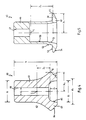
- acceleration acts on acceleration sensor 10 and has an essential component in the x / y plane of coordinate system 11
- this horizontally directed acceleration acts on tilting cone 45, the center of gravity of which, due to massive head 46, is relatively high above the washer 31 lies.
- the tilting cone 45 tilts sideways because the tilting moment acting on it now overcomes the adhesive force exerted by the permanent magnet 30.
- the fulcrum for this tilting movement is the circumferential edge of the collar 48.
- This tilting movement is shown in FIG. 2, it being assumed that the acceleration in the x direction has its maximum value.
- the tilting movement of the cone 45 is indicated by an arrow 55.
- the tilting movement of the tilting cone 45 is guided because the collar 48 of the tilting cone 45 is supported in FIG. 2 with a pivot point on the right peripheral edge on the second cylindrical wall 29 of the second cavity 25.
- a further improvement in the guidance of the tilting cone 45 during the tilting movement can be achieved in that the outside of the second cylindrical extension 35 and the inside of the foot 49 of the tilting cone 45 are each provided with shapes 56, 57 which are complementary to one another, so that the Tilting cone 45 is guided with its foot 49 in the manner of a link guide on the second cylindrical extension 35 during the tilting movement.
- Fig. 3 shows a perspective view of the tilting cone 45, partially cut away, to explain the physical effects that arise during operation.
- the quotient of tear-off acceleration a A and tilting acceleration a K thus corresponds to the quotient of the coordinates z S and x S of the center of gravity S relative to the pivot point D.
- FIG. 4 shows a tilting cone 60, the head of which essentially consists of a continuous cylindrical section 61 which merges downwards into a rotational hyperboloid 62.
- a foot 63 is formed by a conical surface 64 that runs counter to the rotational hyperboloid 62.
- a rounded recess 65 is provided from the underside of the tilting cone 60.
- the tilting cone 60 is provided with a continuous bore 66 over its entire axial height h.
- the axial height h is approximately 10 mm
- the total diameter, ie the double value of x S is approximately 8.8 mm
- the diameter d 1 of the cylindrical portion 61 is approximately 5 mm
- the diameter d 2 the rounded recess 65 is approximately 5 mm
- the outer diameter d3 of the foot 63 is approximately 6 mm
- the inner diameter d4 of the bore 66 is approximately 1.8 mm.
- the average height z F of the pivot point D above the underside of the foot 63 is approximately 2 mm.
- the distance z S of the center of gravity S in the z-axis from the pivot point D is approximately 3.2 mm.
- the angle of inclination ⁇ of the conical surface 64 is approximately 45 °
- the rounded recess 65 has a maximum angle of inclination of approximately 10 °.
- the tilting cone 60 consists of soft iron. It can be arranged, for example, on a permanent magnet which consists of a hard ferrite with the type designation HF 8/22, is axially magnetized and has an outside diameter of 8.8 mm, an inside diameter of 4 mm and a height of 2.25 mm. Flux densities of 200 mT can be achieved with such a holding magnet. If the thickness of the washer 31 is in the range from 0.5 to 1.0 mm, this results in adhesive forces F H of the order of 4 p (0.04 N).
- the ratio of the separation acceleration a A to the tilting acceleration a K corresponding to the ratio of the coordinates z S / x S, is only approx. 0.73. This means that the tilting cone 60 lifts off the permanent magnet 30 at a vertical acceleration which is only 0.73 times the acceleration limit value in the horizontal plane.
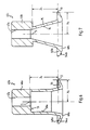
- the tilting cone can be improved by increasing the axial position of the center of gravity S, as will be explained below with reference to FIGS. 5 to 9.
- FIG. 5 shows a first exemplary embodiment of a tilting cone 45, which essentially corresponds to the tilting cone of FIGS. 1 to 3.
- the tilting cone 45 has a lower cylindrical recess 50 which merges downwards into a conical recess 51. Accordingly, the outside of the tilting cone 45 is designed downwards with a conical wall 52 which merges into a flat radial surface 53 of the collar 48. The underside of the collar 48 in the transition to the foot 49 is also designed as a conical surface 54.
- the conical surface 54 can bring about a snap effect in the second working position of the tilting cone 45 (cf. FIG. 2) if the tilting angle of the tilting cone 45 is just as large as the angle of attack of the conical surface 54.
- the tilting cone 45 then lies in the second working position according to FIG. 2 on a surface line of the conical surface 54, so that the holding force in this second working position is relatively high and the tilting cone 45 is locked there until a restoring torque is exerted on it .
- the tilting cone 45 is essentially hollow in the lower region, so that its center of gravity S is significantly higher than is the case with the tilting cone 60 of FIG. 4.
- the extension of the cylindrical recess 50 upwards in the direction of the z-axis leads to a maximum height of the center of gravity S when the center of gravity S is approximately at the upper end of the cylindrical recess 50. If the cylindrical recess 50 is extended further upward, the center of gravity S moves downward again, because then the mass proportions of the foot of the tilting cone 45 are more important than the remaining mass in the area of the head 46 when the overall height h is finite .
- FIG. 5 there is an acceleration quotient of, for example, 1.13, for the sake of comparability in FIGS. 5 to 9 the same scale was chosen as in FIG. 4 and also the sizes h, x S , d1 and d4 as were constantly accepted.
- the configuration of the tilting cone 45a corresponds to that of the tilting cone 45, with the difference that instead of a flat surface 53 in the area of the collar 48, a cavity 70 is now provided in the area of the collar 48a by the mass fraction in the foot area to reduce the cone 45a. If the dimensions remain unchanged, this leads to an increase in the position of the center of gravity S, which in turn leads to an increase in the acceleration quotient to a value of approximately 1.22.
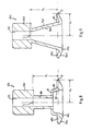
- the tilting cone 45b is constricted radially below the center of gravity S and there it has a conical construction, in order to in turn merge into a collar 48b or foot 49b, which has the corresponding elements 5 corresponds to.
- This construction with conical section 75 and conical recess 76 according to FIG. 7 leads to an acceleration quotient of approximately 1.13.
- the tilting cone 45c is again constricted axially below the center of gravity S, in this case, however, with a cylindrical section 80 of small diameter, which initially merges downwards into a radial widening 81 and then into a conical section 82.
- the recess 83 has the shape of a truncated ball.
- the acceleration quotient is approximately 1.16.
- FIG. 9 shows a variant of a tilting cone 45d, which largely corresponds to the variant according to FIG. 7.
- a hollow 85 is again provided only in the area of the collar 48d in order to reduce the mass fraction in the foot area of the tilting cone 45d.
- the tear-off acceleration a A of the acceleration sensors according to the invention with tilting cones according to FIGS. 5 to 9 can be approx Embodiment of a tilting cone according to FIG. 4 only leads to a tear-off acceleration a A of 3 g.
- This increase in the tear-off acceleration a A from 3 g to 5 g represents a significant improvement in the performance data of the acceleration sensor 10 according to the invention.
- FIG. 10 also shows the dependence of the adhesive force F H over the air gap width z LS , as is realized by the washer 31.
- the course 90 has the known hyperbolic course, the adhesive force F H decreasing with increasing air gap width z LS .
- an operating point 91 can be selected in the flat section of the course 90, at which the dependence of the adhesive force F H on variations in the air gap width z LS is not critical.
- an air gap width z LS of 0.8 to 0.9 mm can be set in order to achieve an adhesive force F H of between 3 and 4 p (0.03 to 0.04 N).
Landscapes
- Physics & Mathematics (AREA)
- General Physics & Mathematics (AREA)
- Switches Operated By Changes In Physical Conditions (AREA)
- Air Bags (AREA)
- Measurement Of Mechanical Vibrations Or Ultrasonic Waves (AREA)
- Force Measurement Appropriate To Specific Purposes (AREA)
Claims (4)
- Capteur d'accélération (10) avec un photoémetteur (21) et un photo-récepteur (37), disposés en étant tournés l'un vers l'autre sur un axe optique (z) avec une partie basculante (45; 60), symétrique en rotation par rapport à l'axe (z), disposée, dans une première position de travail, coaxialement par rapport à l'axe (z) et présentant un alésage traversant (47; 66) coaxial par rapport à l'axe (z), de sorte qu'un rayon lumineux (26) partant du photo-émetteur (21) et passant par l'alésage traversant (47; 66) arrive au photorécepteur (37), avec des moyens de maintien (30, 31) pour fixer la partie basculante (45; 60) dans la première position de travail, avec une force prédéterminée (FH) en direction de l'axe (z), sur une surface de contact (A) et avec des moyens de guidage (27, 29, 31, 46, 48, 49), qui, en cas d'une accélération (aK) agissant sur la partie basculante (45; 60) et orientée dans une direction (x, y) perpendiculaire à l'axe (z), permettent, en surmontant la force (FH) prédéterminée, un mouvement de basculement (55) limité de la partie basculante (45; 60), autour d'un centre de rotation (D) disposé à distance (xS) de l'axe, pour passer dans une deuxième position de travail, de telle façon que l'alésage traversant (47; 66) soit basculé à l'écart de la trajectoire du rayon lumineux (26), la partie basculante (45) étant réalisée de telle façon, concernant la distribution spatiale de sa masse, et avec son centre de gravité (S) placé de telle façon par rapport au centre de rotation (D), que le rapport entre l'accélération d'arrachement (aA) nécessaire au soulèvement de la partie basculante (45) en direction de l'axe (z) et l'accélération de basculement (aK) nécessaire au basculement de la partie basculante (45) autour du centre de rotation (D) est supérieure à un, et où la partie basculante (45; 60) est pourvue d'une collerette (48) faisant saillie radialement, dont le bord circulaire est le lieu du centre de rotation (D), caractérisé en ce que le bord circulaire de la collerette (48) faisant saillie radialement est situé à une distance verticale (zF) par rapport à la surface de pose (A) et que la partie basculante (45; 60) est composée d'un matériau ferromagnétique, et les moyens de maintien présentant un aimant (30) avec une magnétisation axiale, sur lequel la partie basculante (45, 60) repose, lorsqu'elle est dans la première position travail.
- Capteur d'accélération selon la revendication 1, caractérisé en ce que la partie basculante (45; 60) est pourvue d'une tête (46, 61) à peu près cylindrique, se transformant en partie inférieure en la collerette (48) faisant saillie radialement et en ce que la tête (46b; 46c; 46d) est réalisée en allant en s'effilant (75; 80) au-dessous du centre de gravité (S).
- Capteur d'accélération selon la revendication 1 ou 2, caractérisé en ce que la collerette (48a; 48d) est pourvue d'une échancrure circulaire (70; 85).
- Capteur d'accélération selon l'une ou plusieurs des revendications 1 à 3, caractérisé en ce qu'une rondelle intercalaire (31) d'épaisseur prédéterminée, non magnétique, est disposée entre la partie basculante (45) et l'aimant (30).
Applications Claiming Priority (2)
| Application Number | Priority Date | Filing Date | Title |
|---|---|---|---|
| DE3819759A DE3819759C1 (fr) | 1988-06-10 | 1988-06-10 | |
| DE3819759 | 1988-06-10 |
Publications (3)
| Publication Number | Publication Date |
|---|---|
| EP0345722A2 EP0345722A2 (fr) | 1989-12-13 |
| EP0345722A3 EP0345722A3 (fr) | 1991-02-20 |
| EP0345722B1 true EP0345722B1 (fr) | 1993-09-29 |
Family
ID=6356262
Family Applications (1)
| Application Number | Title | Priority Date | Filing Date |
|---|---|---|---|
| EP89110207A Expired - Lifetime EP0345722B1 (fr) | 1988-06-10 | 1989-06-06 | Capteur d'accélération |
Country Status (4)
| Country | Link |
|---|---|
| US (1) | US5013909A (fr) |
| EP (1) | EP0345722B1 (fr) |
| JP (1) | JPH0648276B2 (fr) |
| DE (2) | DE3819759C1 (fr) |
Families Citing this family (22)
| Publication number | Priority date | Publication date | Assignee | Title |
|---|---|---|---|---|
| DE4129801A1 (de) * | 1991-09-07 | 1993-03-11 | Bosch Gmbh Robert | Sensor zum selbsttaetigen ausloesen von sicherheitseinrichtungen in kraftfahrzeugen |
| DE4209272A1 (de) * | 1992-03-21 | 1993-09-23 | Bosch Gmbh Robert | Sensor |
| US5744872A (en) * | 1995-07-14 | 1998-04-28 | Trw Inc. | Inertia responsive apparatus |
| AU7099398A (en) | 1997-04-01 | 1998-10-22 | Kelsey-Hayes Company | Mounting structure for an acceleration sensor |
| US6005241A (en) * | 1997-10-24 | 1999-12-21 | Takata Corporation | Seat belt restraint system |
| WO2001044751A1 (fr) * | 1999-12-15 | 2001-06-21 | Peter Bryan Webster | Capteur de position |
| US6723979B2 (en) * | 2001-02-27 | 2004-04-20 | Delphi Technologies, Inc | Roll arming sensor |
| US6858835B2 (en) * | 2002-05-13 | 2005-02-22 | Federal-Mogul World Wide, Inc. | Electronic tilt switch and integrated light module |
| US7793543B2 (en) * | 2007-05-04 | 2010-09-14 | Baker Hughes Incorporated | Method of measuring borehole gravitational acceleration |
| US20090308158A1 (en) * | 2008-06-13 | 2009-12-17 | Bard Arnold D | Optical Accelerometer |
| US20120024062A1 (en) * | 2010-07-30 | 2012-02-02 | Tiefel Simeon E | Low Cost Optical Accelerometer |
| CN105548612B (zh) * | 2015-06-08 | 2016-11-30 | 福州睿创纺织科技有限公司 | 一种基于发光二极管的加速度传感器 |
| CN105652036B (zh) * | 2015-06-08 | 2016-11-30 | 福州睿创纺织科技有限公司 | 一种基于发光频率的加速度传感器 |
| US11079227B2 (en) | 2019-04-01 | 2021-08-03 | Honeywell International Inc. | Accelerometer system enclosing gas |
| US11119116B2 (en) | 2019-04-01 | 2021-09-14 | Honeywell International Inc. | Accelerometer for determining an acceleration based on modulated optical signals |
| US10705112B1 (en) | 2019-04-22 | 2020-07-07 | Honeywell International Inc. | Noise rejection for optomechanical devices |
| US10956768B2 (en) | 2019-04-22 | 2021-03-23 | Honeywell International Inc. | Feedback cooling and detection for optomechanical devices |
| US11119114B2 (en) | 2019-07-17 | 2021-09-14 | Honeywell International Inc. | Anchor structure for securing optomechanical structure |
| US11408911B2 (en) | 2019-07-17 | 2022-08-09 | Honeywell International Inc. | Optomechanical structure with corrugated edge |
| US11372019B2 (en) | 2019-08-13 | 2022-06-28 | Honeywell International Inc. | Optomechanical resonator stabilization for optomechanical devices |
| US11150264B2 (en) | 2019-08-13 | 2021-10-19 | Honeywell International Inc. | Feedthrough rejection for optomechanical devices using elements |
| US11408912B2 (en) | 2019-08-13 | 2022-08-09 | Honeywell International Inc. | Feedthrough rejection for optomechanical devices |
Family Cites Families (7)
| Publication number | Priority date | Publication date | Assignee | Title |
|---|---|---|---|---|
| US3778572A (en) * | 1971-03-25 | 1973-12-11 | Nissan Motor | Inertia sensor switch assemblies with magnetic holding means or the like |
| US3798454A (en) * | 1972-04-25 | 1974-03-19 | Us Navy | Device for counting accelerations, measuring magnitudes thereof, recording and classifying the same according to magnitude |
| DE3022878C2 (de) * | 1980-06-19 | 1984-08-09 | Helba Elektronik-Baugruppen Gmbh & Co Kg, 5628 Heiligenhaus | Beschleunigungsgrenzwertschalter |
| DE8310623U1 (de) * | 1983-04-12 | 1983-09-08 | Helba Elektronik-Baugruppen Gmbh & Co Kg, 5628 Heiligenhaus | Beschleunigungsgrenzwertschalter |
| SE455183B (sv) * | 1984-04-13 | 1988-06-27 | Autoliv Dev | Anordning for avkenning av en staende, vippbar troghetskropps lege i ett sekerhetssystem for fordon |
| DE3540947A1 (de) * | 1985-11-19 | 1987-05-21 | Bosch Gmbh Robert | Beschleunigungsaufnehmer |
| DE3725758C1 (fr) * | 1987-08-04 | 1988-09-01 | Daimler-Benz Ag, 7000 Stuttgart, De |
-
1988
- 1988-06-10 DE DE3819759A patent/DE3819759C1/de not_active Expired - Fee Related
-
1989
- 1989-06-06 DE DE89110207T patent/DE58905737D1/de not_active Expired - Fee Related
- 1989-06-06 EP EP89110207A patent/EP0345722B1/fr not_active Expired - Lifetime
- 1989-06-08 US US07/363,207 patent/US5013909A/en not_active Expired - Lifetime
- 1989-06-09 JP JP1145558A patent/JPH0648276B2/ja not_active Expired - Lifetime
Also Published As
| Publication number | Publication date |
|---|---|
| DE58905737D1 (de) | 1993-11-04 |
| EP0345722A3 (fr) | 1991-02-20 |
| DE3819759C1 (fr) | 1990-02-15 |
| EP0345722A2 (fr) | 1989-12-13 |
| JPH0648276B2 (ja) | 1994-06-22 |
| US5013909A (en) | 1991-05-07 |
| JPH0236361A (ja) | 1990-02-06 |
Similar Documents
| Publication | Publication Date | Title |
|---|---|---|
| EP0345722B1 (fr) | Capteur d'accélération | |
| EP0248940B1 (fr) | Relais de déclenchement d'un tendeur de ceinture de sécurité pour véhicule | |
| DE2228683C2 (de) | Beschleunigungs- und verzögerungsabhängige, elektrische Schaltvorrichtung zum Einbau in Fahrzeuge | |
| DE3402387C2 (de) | Beschleunigungsgrenzwertschalter | |
| DE2630553A1 (de) | Fahrzeugempfindliche sperreinrichtung fuer automatikgurte | |
| DE3785294T2 (de) | Neigungsmesser. | |
| EP0510139B1 (fr) | Acceleromètre | |
| DE2828202C3 (de) | Schwingungsfühler | |
| EP0349730B1 (fr) | Détecteur d'accélération pour véhicules | |
| DE4035257A1 (de) | Beschleunigungssensor | |
| DE69409750T2 (de) | In mehreren Richtungen empfindlicher Stossmessaufnehmer | |
| DE3725758C1 (fr) | ||
| EP1010593A2 (fr) | Capteur pour un rétracteur de sangle | |
| EP0251048B1 (fr) | Capteur d'accélération | |
| DE2621306A1 (de) | Seismonastischer schalter | |
| DE19547608B4 (de) | Sensoranordnung | |
| WO1993019377A1 (fr) | Capteur | |
| EP0950878A1 (fr) | Dispositif pour la détection d'un niveau de liquide | |
| DE3512486C2 (fr) | ||
| DE4101060A1 (de) | Neigungssensor | |
| DE2942551C2 (fr) | ||
| DE1944732C3 (de) | Elektrischer Trägheitsschalter | |
| DD252592A1 (de) | Verfahren und vorrichtung zum beruehrungslosen erfassen des fuellungsgrades an vorgarnhuelsen | |
| DE69912471T2 (de) | Bidirektionaler stosssensor mit reedschalter | |
| DE29601148U1 (de) | Warnblinkanordnung |
Legal Events
| Date | Code | Title | Description |
|---|---|---|---|
| PUAI | Public reference made under article 153(3) epc to a published international application that has entered the european phase |
Free format text: ORIGINAL CODE: 0009012 |
|
| AK | Designated contracting states |
Kind code of ref document: A2 Designated state(s): DE FR GB IT SE |
|
| PUAL | Search report despatched |
Free format text: ORIGINAL CODE: 0009013 |
|
| AK | Designated contracting states |
Kind code of ref document: A3 Designated state(s): DE FR GB IT SE |
|
| 17P | Request for examination filed |
Effective date: 19910220 |
|
| 17Q | First examination report despatched |
Effective date: 19911223 |
|
| GRAA | (expected) grant |
Free format text: ORIGINAL CODE: 0009210 |
|
| AK | Designated contracting states |
Kind code of ref document: B1 Designated state(s): DE FR GB IT SE |
|
| PG25 | Lapsed in a contracting state [announced via postgrant information from national office to epo] |
Ref country code: IT Free format text: LAPSE BECAUSE OF FAILURE TO SUBMIT A TRANSLATION OF THE DESCRIPTION OR TO PAY THE FEE WITHIN THE PRE;WARNING: LAPSES OF ITALIAN PATENTS WITH EFFECTIVE DATE BEFORE 2007 MAY HAVE OCCURRED AT ANY TIME BEFORE 2007. THE CORRECT EFFECTIVE DATE MAY BE DIFFERENT FROM THE ONE RECORDED.SCRIBED TIME-LIMIT Effective date: 19930929 |
|
| REF | Corresponds to: |
Ref document number: 58905737 Country of ref document: DE Date of ref document: 19931104 |
|
| ET | Fr: translation filed | ||
| GBT | Gb: translation of ep patent filed (gb section 77(6)(a)/1977) |
Effective date: 19931223 |
|
| PLBE | No opposition filed within time limit |
Free format text: ORIGINAL CODE: 0009261 |
|
| STAA | Information on the status of an ep patent application or granted ep patent |
Free format text: STATUS: NO OPPOSITION FILED WITHIN TIME LIMIT |
|
| 26N | No opposition filed | ||
| EAL | Se: european patent in force in sweden |
Ref document number: 89110207.1 |
|
| REG | Reference to a national code |
Ref country code: GB Ref legal event code: IF02 |
|
| PGFP | Annual fee paid to national office [announced via postgrant information from national office to epo] |
Ref country code: SE Payment date: 20070614 Year of fee payment: 19 |
|
| PGFP | Annual fee paid to national office [announced via postgrant information from national office to epo] |
Ref country code: DE Payment date: 20070727 Year of fee payment: 19 |
|
| PGFP | Annual fee paid to national office [announced via postgrant information from national office to epo] |
Ref country code: GB Payment date: 20070621 Year of fee payment: 19 |
|
| PGFP | Annual fee paid to national office [announced via postgrant information from national office to epo] |
Ref country code: FR Payment date: 20070615 Year of fee payment: 19 |
|
| EUG | Se: european patent has lapsed | ||
| GBPC | Gb: european patent ceased through non-payment of renewal fee |
Effective date: 20080606 |
|
| REG | Reference to a national code |
Ref country code: FR Ref legal event code: ST Effective date: 20090228 |
|
| PG25 | Lapsed in a contracting state [announced via postgrant information from national office to epo] |
Ref country code: DE Free format text: LAPSE BECAUSE OF NON-PAYMENT OF DUE FEES Effective date: 20090101 |
|
| PG25 | Lapsed in a contracting state [announced via postgrant information from national office to epo] |
Ref country code: GB Free format text: LAPSE BECAUSE OF NON-PAYMENT OF DUE FEES Effective date: 20080606 |
|
| PG25 | Lapsed in a contracting state [announced via postgrant information from national office to epo] |
Ref country code: FR Free format text: LAPSE BECAUSE OF NON-PAYMENT OF DUE FEES Effective date: 20080630 |
|
| PG25 | Lapsed in a contracting state [announced via postgrant information from national office to epo] |
Ref country code: SE Free format text: LAPSE BECAUSE OF NON-PAYMENT OF DUE FEES Effective date: 20080607 |