EP0345700A1 - Carter d'échappement pour turbomachine - Google Patents
Carter d'échappement pour turbomachine Download PDFInfo
- Publication number
- EP0345700A1 EP0345700A1 EP89110149A EP89110149A EP0345700A1 EP 0345700 A1 EP0345700 A1 EP 0345700A1 EP 89110149 A EP89110149 A EP 89110149A EP 89110149 A EP89110149 A EP 89110149A EP 0345700 A1 EP0345700 A1 EP 0345700A1
- Authority
- EP
- European Patent Office
- Prior art keywords
- diffuser
- housing body
- wall
- housing
- outflow channel
- Prior art date
- Legal status (The legal status is an assumption and is not a legal conclusion. Google has not performed a legal analysis and makes no representation as to the accuracy of the status listed.)
- Granted
Links
Images

Classifications
-
- F—MECHANICAL ENGINEERING; LIGHTING; HEATING; WEAPONS; BLASTING
- F01—MACHINES OR ENGINES IN GENERAL; ENGINE PLANTS IN GENERAL; STEAM ENGINES
- F01D—NON-POSITIVE DISPLACEMENT MACHINES OR ENGINES, e.g. STEAM TURBINES
- F01D25/00—Component parts, details, or accessories, not provided for in, or of interest apart from, other groups
- F01D25/30—Exhaust heads, chambers, or the like
Definitions
- the invention relates to an outlet housing of a turbomachine, in which an axially directed inflow changes into an outflow perpendicular to the machine axis.
- the invention is particularly suitable for outlet casings of steam turbines which are arranged between the last stage of the steam turbine and the condenser.
- outlet housings which contain an axisymmetric diffuser and a voluminous housing which merges into an inlet port of the condenser.
- the housing contains a cylinder wall, the surface lines of which are parallel to the machine axis. The flowing medium was found to be the Housing walls do not flow smoothly, but extensive vortices arise, which leads to considerable energy losses.
- Another known outlet housing has two opposite outlets through which the steam flows into two independent condensers. This outlet housing results in lower energy losses, but for the price of a considerable outlay due to the two capacitors required and their accommodation in the machine room.
- the object of the invention is to provide an outlet housing for turbomachines which ensures reduced energy losses with relatively little technical effort.
- the outlet housing for turbomachines contains a body, a circular diffuser, walls and partitions.
- the body includes a straight channel through which approximately one half of the steam flows and a bypass channel of constant width which guides the remaining steam flow around the circular diffuser in the same direction in which the steam flows in the straight channel.
- the straight channel begins in accordance with the flow through the circular diffuser at the location immediately behind the transverse axis of the diffuser and leads towards its center towards the lower part of the body and occupies the rear portion of this lower part of the body.
- the bypass channel begins next to the straight channel at the end of the diffuser and leads in an upward direction and against the direction of flow in the diffuser Elbow in a straight channel section, which opens into a common discharge channel arranged transversely to the machine axis.
- the outer jacket of the circulation channel thus forms part of the upper part of the rear wall of the housing body, to which the outer cylinder wall connects, which connects to the front wall of the housing body.
- the inner jacket of the circulation channel forms a convex wall in the upper part of the housing body, which connects to the upper edge of the diffuser jacket and merges into an inclined wall, which gradually leads back and connects to a vertical partition in the lower part of the housing body in the immediate vicinity of the transverse axis of the diffuser, which separates the front portion of the housing body from the rear.
- the outer casing of the straight channel forms the rear wall of the lower part of the housing body and its inner casing forms the rear oblique wall, which begins at the lower edge of the diffuser casing near the transverse plane of the diffuser and is connected to the opposite edge of the partition or partition, which separates the rear section from the front section of the housing body.
- the side jacket of the straight channel and the circulation channel forms the right and left side wall of the housing body.
- One embodiment of the invention contains dividers in the straight channel and the circulation channel, the common edges of the first manifold being connected to one another and also the common edge of the second distributor being connected to one another. These connections are connected at the opposite points of the diffuser jacket, namely horizontally in the immediate vicinity of the transverse axis of the diffuser.
- the distributors are connected with their outer edges to the side walls of the housing body so that the individual distributors are concave with respect to the vertical axis of this body.
- a pair of streamlined baffles or dividing walls are arranged horizontally in the circulation channel at opposite points of the diffuser jacket immediately behind its transverse axis, the opposite edges of which are connected to one another in the vertical axis of the housing body.
- the vertical baffles can expediently be inserted between the streamlined partition walls and the side walls of the body of the outlet housing.
- An advantage of the outlet housing according to the invention is the substantial reduction in the wake and swirl areas, which leads to a substantial reduction in the energy losses of the turbomachine. Another advantage is that the original dimensions of the housing and its external shape are roughly preserved.
- the housing according to the invention is produced from the shaped sheets.
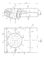
- the illustrated outlet housing for a turbomachine contains a body 01 which is rectangular in elevation and a circular diffuser d.
- the circular diffuser d consists of a trumpet-shaped jacket tube p open at the rear and a core j with a widened end part.
- the opening of the casing tube p is larger than the broadening of the core j, so that the circular cross-section of the diffuser d, which is delimited by both, widens towards the rear.
- the widened end of the core j is connected to the inside of the rear wall 100 of the body 01.
- the body 01 of the outlet housing is only supposed to be distributed vertically on the upper part H and the lower part D.
- the dividing line 14 between the upper part H and the lower part D runs below parallel or in alignment with the transverse axis z of the diffuser d.
- This assumed dividing line is an extension of the fictitious dividing plane between the proportion of steam flowing through the diffuser d into a straight duct I and the quantity of steam flowing into a circulation duct II.
- a distribution of the steam flow exists in every diffuser of flow machines of this type.
- the length D of the lower part D of the body 01 is divided by a partition 8 into two equal halves, ie into a rear section Z and a front section P.
- the straight channel I is accommodated in such a way that a rear oblique wall 4 is connected to the lower edge d2 of the diffuser d, which begins at the dividing line 14 and leads to the dividing wall 8.
- the circulation channel II begins in the upper part of the Kör pers 01, the outer cylinder wall 5 being connected to its end wall 100, the bending diameter of which corresponds to the sum of the width of the rear and front sections Z, P.
- the cylinder wall 5 merges into the front wall 200 of the body 01.
- the inner jacket of the circulation channel II forms a convex wall 7, which begins in the dividing line 14 and is connected to the upper end edge d1 of the diffuser d.
- 3 and 4 are in the straight channel I and the circulation channel II, in the immediate vicinity of the transverse axis z of the diffuser d, ie in the dividing line 14, two common edges 12, 13 of a first distributor 1 and a second Distributor 2 housed vertically and against each other and connected there to the outer jacket p of the circular diffuser d.
- These distributors 1, 2 are connected to the side walls 3, 6 via outer edges.
- the first and the second distributors 1, 2 are arcuate concave to the vertical axis x of the body 01.
- the steam flow from the last stage of the turbomachine enters the circular diffuser d and divides into a back through the straight channel 100 z. B. to the capacitors flowing lower part and in an upper partial flow, which is turned by the upper edge d1 of the diffuser, the convex wall 7 and the outer cylinder wall 7 and then guided along the casing tube p into the circulation channel II. Both steam parts then flow in the same direction in channels I and II.
- the distribution of the steam flow on the upper and lower flow is supported by distributors 1 and 2, on the surfaces of which the steam flows smoothly and does not form any eddies.
- the rear sloping wall 4 also essentially follows the streamlines of the steam and supports its uniform, continuous flow.
- the front sloping wall 11 in the circulation channel serves the same purpose.
- the two streamlined partitions 9 eliminate the risk of swirling in the area behind the lower edge d2 of the diffuser d and their streamlined shape also improves the swirl-free continuous steam flow.
- the baffles 10 reduce the swirl of the fluid by dividing the flow width into several narrower flows. The use of guide elements and / or partitions is matched to the characteristics of the respective turbomachine.
Landscapes
- Engineering & Computer Science (AREA)
- Mechanical Engineering (AREA)
- General Engineering & Computer Science (AREA)
- Turbine Rotor Nozzle Sealing (AREA)
Applications Claiming Priority (2)
| Application Number | Priority Date | Filing Date | Title |
|---|---|---|---|
| CS3927/88 | 1988-06-07 | ||
| CS392788A CS272676B1 (en) | 1988-06-07 | 1988-06-07 | Outlet branch for bladed machine |
Publications (2)
| Publication Number | Publication Date |
|---|---|
| EP0345700A1 true EP0345700A1 (fr) | 1989-12-13 |
| EP0345700B1 EP0345700B1 (fr) | 1992-08-26 |
Family
ID=5380750
Family Applications (1)
| Application Number | Title | Priority Date | Filing Date |
|---|---|---|---|
| EP19890110149 Expired - Lifetime EP0345700B1 (fr) | 1988-06-07 | 1989-06-05 | Carter d'échappement pour turbomachine |
Country Status (3)
| Country | Link |
|---|---|
| EP (1) | EP0345700B1 (fr) |
| CS (1) | CS272676B1 (fr) |
| DE (1) | DE58902123D1 (fr) |
Cited By (10)
| Publication number | Priority date | Publication date | Assignee | Title |
|---|---|---|---|---|
| EP0558652A1 (fr) * | 1990-11-21 | 1993-09-08 | Norlock Technologies, Inc. | Procede et appareil servant a ameliorer l'efficacite de l'ecoulement dans des turbo-moteurs a gaz |
| WO1997016628A2 (fr) * | 1995-10-31 | 1997-05-09 | Siemens Aktiengesellschaft | Element de transition entre des elements constitutifs du canal de gaz brules d'une turbine a gaz |
| FR2757210A1 (fr) * | 1996-12-12 | 1998-06-19 | Hispano Suiza Sa | Echappement centrifuge de turbine a deflecteur cambre |
| WO1998055739A1 (fr) * | 1997-06-05 | 1998-12-10 | Abb Stal Ab | Dispositif d'evacuation destine a une machine a circulation de flux |
| WO1999020874A1 (fr) * | 1997-10-17 | 1999-04-29 | Zakrytoe Aktsionernoe Obschestvo 'entek' | Conduit d'evacuation pour turbine a vapeur |
| WO1999051858A1 (fr) | 1998-04-06 | 1999-10-14 | Siemens Aktiengesellschaft | Turbine a vapeur |
| US6062814A (en) * | 1995-10-31 | 2000-05-16 | Siemens Aktiengesellschaft | Transition element between components of a flue-gas duct of a gas turbine |
| JP2006307738A (ja) * | 2005-04-28 | 2006-11-09 | Toshiba Corp | 蒸気タービン |
| EP1892384A1 (fr) * | 2006-08-25 | 2008-02-27 | Siemens Aktiengesellschaft | Diffuseur pour une turbine à vapeur |
| EP1992789A1 (fr) * | 2007-05-18 | 2008-11-19 | ABB Turbo Systems AG | Carter de turbine à gas d'échappement comprenant un élément de support |
Families Citing this family (1)
| Publication number | Priority date | Publication date | Assignee | Title |
|---|---|---|---|---|
| CZ302698B6 (cs) * | 2009-05-19 | 2011-09-07 | Ceské vysoké ucení technické v Praze | Prechodový díl lopatkového stroje |
Citations (4)
| Publication number | Priority date | Publication date | Assignee | Title |
|---|---|---|---|---|
| FR1110063A (fr) * | 1953-10-23 | 1956-02-06 | Licentia Gmbh | Diffuseur annulaire placé avant la chambre d'échappement de la vapeur ou du gaz d'une turbine à vapeur ou à gaz |
| US3149470A (en) * | 1962-08-29 | 1964-09-22 | Gen Electric | Low pressure turbine exhaust hood |
| FR2381907A1 (fr) * | 1977-02-24 | 1978-09-22 | Maschf Augsburg Nuernberg Ag | Turbomachine pour fluides gazeux avec echangeur de chaleur |
| US4326832A (en) * | 1978-11-14 | 1982-04-27 | Tokyo Shibaura Denki Kabushiki Kaisha | Exhaust outer casing |
-
1988
- 1988-06-07 CS CS392788A patent/CS272676B1/cs unknown
-
1989
- 1989-06-05 EP EP19890110149 patent/EP0345700B1/fr not_active Expired - Lifetime
- 1989-06-05 DE DE8989110149T patent/DE58902123D1/de not_active Expired - Fee Related
Patent Citations (4)
| Publication number | Priority date | Publication date | Assignee | Title |
|---|---|---|---|---|
| FR1110063A (fr) * | 1953-10-23 | 1956-02-06 | Licentia Gmbh | Diffuseur annulaire placé avant la chambre d'échappement de la vapeur ou du gaz d'une turbine à vapeur ou à gaz |
| US3149470A (en) * | 1962-08-29 | 1964-09-22 | Gen Electric | Low pressure turbine exhaust hood |
| FR2381907A1 (fr) * | 1977-02-24 | 1978-09-22 | Maschf Augsburg Nuernberg Ag | Turbomachine pour fluides gazeux avec echangeur de chaleur |
| US4326832A (en) * | 1978-11-14 | 1982-04-27 | Tokyo Shibaura Denki Kabushiki Kaisha | Exhaust outer casing |
Cited By (18)
| Publication number | Priority date | Publication date | Assignee | Title |
|---|---|---|---|---|
| EP0558652A4 (fr) * | 1990-11-21 | 1994-01-19 | Thomas R. Norris | |
| EP0558652A1 (fr) * | 1990-11-21 | 1993-09-08 | Norlock Technologies, Inc. | Procede et appareil servant a ameliorer l'efficacite de l'ecoulement dans des turbo-moteurs a gaz |
| US6062814A (en) * | 1995-10-31 | 2000-05-16 | Siemens Aktiengesellschaft | Transition element between components of a flue-gas duct of a gas turbine |
| WO1997016628A2 (fr) * | 1995-10-31 | 1997-05-09 | Siemens Aktiengesellschaft | Element de transition entre des elements constitutifs du canal de gaz brules d'une turbine a gaz |
| WO1997016628A3 (fr) * | 1995-10-31 | 1997-07-03 | Siemens Ag | Element de transition entre des elements constitutifs du canal de gaz brules d'une turbine a gaz |
| FR2757210A1 (fr) * | 1996-12-12 | 1998-06-19 | Hispano Suiza Sa | Echappement centrifuge de turbine a deflecteur cambre |
| WO1998055739A1 (fr) * | 1997-06-05 | 1998-12-10 | Abb Stal Ab | Dispositif d'evacuation destine a une machine a circulation de flux |
| US6231304B1 (en) | 1997-06-05 | 2001-05-15 | Abb Stal Ab | Outlet device for a flow machine |
| WO1999020874A1 (fr) * | 1997-10-17 | 1999-04-29 | Zakrytoe Aktsionernoe Obschestvo 'entek' | Conduit d'evacuation pour turbine a vapeur |
| CN1089136C (zh) * | 1997-10-17 | 2002-08-14 | Entek股份有限公司 | 蒸气涡轮机排气管 |
| WO1999051858A1 (fr) | 1998-04-06 | 1999-10-14 | Siemens Aktiengesellschaft | Turbine a vapeur |
| JP2002510769A (ja) * | 1998-04-06 | 2002-04-09 | シーメンス アクチエンゲゼルシヤフト | 蒸気タービン |
| JP2006307738A (ja) * | 2005-04-28 | 2006-11-09 | Toshiba Corp | 蒸気タービン |
| JP4557787B2 (ja) * | 2005-04-28 | 2010-10-06 | 株式会社東芝 | 蒸気タービン |
| EP1892384A1 (fr) * | 2006-08-25 | 2008-02-27 | Siemens Aktiengesellschaft | Diffuseur pour une turbine à vapeur |
| EP1992789A1 (fr) * | 2007-05-18 | 2008-11-19 | ABB Turbo Systems AG | Carter de turbine à gas d'échappement comprenant un élément de support |
| WO2008142044A2 (fr) * | 2007-05-18 | 2008-11-27 | Abb Turbo Systems Ag | Enveloppe de turbine |
| WO2008142044A3 (fr) * | 2007-05-18 | 2009-11-19 | Abb Turbo Systems Ag | Enveloppe de turbine |
Also Published As
| Publication number | Publication date |
|---|---|
| CS272676B1 (en) | 1991-02-12 |
| EP0345700B1 (fr) | 1992-08-26 |
| CS392788A1 (en) | 1990-06-13 |
| DE58902123D1 (de) | 1992-10-01 |
Similar Documents
| Publication | Publication Date | Title |
|---|---|---|
| DE60016937T2 (de) | Antiwirbelsystem für kreiselverdichter | |
| EP1223308B1 (fr) | Composante d'une turbomachine | |
| DE2934041C2 (de) | Gesteuerte Abgasturboladerturbine | |
| DE3534905C2 (de) | Gekühlte hohle Turbinenschaufel | |
| DE2547229C2 (de) | Luftabzweigeinrichtung für einen Axialverdichter eines Gasturbinentriebwerks | |
| AT2490U1 (de) | Kühleranordnung für eine aufgeladene brennkraftmaschine mit abgasrückführung | |
| EP2495425A2 (fr) | Dispositif de moteur à réaction doté d'un canal de courant auxiliaire | |
| DE2942143A1 (de) | Gehaeuse fuer ein turbinenrad | |
| EP0345700B1 (fr) | Carter d'échappement pour turbomachine | |
| EP0799973A1 (fr) | Contour de paroi pour une turbomachine axiale | |
| DE3421792A1 (de) | Radialturbine mit veraenderlicher kapazitaet, mit einem schwenkbaren zungenteil | |
| DE2632155A1 (de) | Geblaese-gasturbinenstrahltriebwerk | |
| DE3803010A1 (de) | Turbine eines abgasturboladers | |
| WO2016096813A1 (fr) | Conduite d'air pour une tubulure d'admission de moteur à combustion interne, en particulier d'un véhicule à moteur | |
| DE3121341C2 (de) | Abgasleitungssystem zwischen einer nach dem Stauprinzip aufgeladenen, mehrzylindrigen Brennkraftmaschine und einem Abgasturbolader | |
| DE602004006035T2 (de) | Kühleinrichtung für Turbinenscheiben | |
| DE3203342C2 (de) | Luftkanal zur Zuführung von Druckluft bei einer Gasturbinenanlage | |
| DE10145489B4 (de) | Anordnung zum Vermischen von zwei ursprünglich getrennt geführten Fluidströmen in einem Zweikreis-Strahltriebwerk | |
| DE3614467C2 (de) | Beschaufeltes Gitter für Gastrubinentriebwerke | |
| DE3916008C1 (fr) | ||
| DE2708809C2 (fr) | ||
| DE3630488A1 (de) | Laengenveraenderbares saugrohr fuer eine brennkraftmaschine | |
| DE10060705A1 (de) | Motorunabhängiges Heizgerät eines Kraftfahrzeuges | |
| DE1601627B2 (de) | Gekuehlte schaufel fuer eine stroemungsmaschine | |
| EP1353054B1 (fr) | Turbopropulseur |
Legal Events
| Date | Code | Title | Description |
|---|---|---|---|
| PUAI | Public reference made under article 153(3) epc to a published international application that has entered the european phase |
Free format text: ORIGINAL CODE: 0009012 |
|
| AK | Designated contracting states |
Kind code of ref document: A1 Designated state(s): CH DE FR GB IT LI SE |
|
| 17P | Request for examination filed |
Effective date: 19900208 |
|
| 17Q | First examination report despatched |
Effective date: 19910318 |
|
| GRAA | (expected) grant |
Free format text: ORIGINAL CODE: 0009210 |
|
| AK | Designated contracting states |
Kind code of ref document: B1 Designated state(s): CH DE FR GB IT LI SE |
|
| ITF | It: translation for a ep patent filed |
Owner name: ING. C. GREGORJ S.P.A. |
|
| GBT | Gb: translation of ep patent filed (gb section 77(6)(a)/1977) | ||
| REF | Corresponds to: |
Ref document number: 58902123 Country of ref document: DE Date of ref document: 19921001 |
|
| ET | Fr: translation filed | ||
| PLBE | No opposition filed within time limit |
Free format text: ORIGINAL CODE: 0009261 |
|
| STAA | Information on the status of an ep patent application or granted ep patent |
Free format text: STATUS: NO OPPOSITION FILED WITHIN TIME LIMIT |
|
| 26N | No opposition filed | ||
| EAL | Se: european patent in force in sweden |
Ref document number: 89110149.5 |
|
| PGFP | Annual fee paid to national office [announced via postgrant information from national office to epo] |
Ref country code: GB Payment date: 19960528 Year of fee payment: 8 |
|
| PGFP | Annual fee paid to national office [announced via postgrant information from national office to epo] |
Ref country code: FR Payment date: 19960611 Year of fee payment: 8 |
|
| PGFP | Annual fee paid to national office [announced via postgrant information from national office to epo] |
Ref country code: DE Payment date: 19960612 Year of fee payment: 8 |
|
| PGFP | Annual fee paid to national office [announced via postgrant information from national office to epo] |
Ref country code: SE Payment date: 19960619 Year of fee payment: 8 |
|
| PGFP | Annual fee paid to national office [announced via postgrant information from national office to epo] |
Ref country code: CH Payment date: 19960620 Year of fee payment: 8 |
|
| PG25 | Lapsed in a contracting state [announced via postgrant information from national office to epo] |
Ref country code: GB Free format text: LAPSE BECAUSE OF NON-PAYMENT OF DUE FEES Effective date: 19970605 |
|
| PG25 | Lapsed in a contracting state [announced via postgrant information from national office to epo] |
Ref country code: SE Effective date: 19970606 |
|
| PG25 | Lapsed in a contracting state [announced via postgrant information from national office to epo] |
Ref country code: LI Free format text: LAPSE BECAUSE OF NON-PAYMENT OF DUE FEES Effective date: 19970630 Ref country code: CH Free format text: LAPSE BECAUSE OF NON-PAYMENT OF DUE FEES Effective date: 19970630 |
|
| GBPC | Gb: european patent ceased through non-payment of renewal fee |
Effective date: 19970605 |
|
| REG | Reference to a national code |
Ref country code: CH Ref legal event code: PL |
|
| PG25 | Lapsed in a contracting state [announced via postgrant information from national office to epo] |
Ref country code: FR Free format text: LAPSE BECAUSE OF NON-PAYMENT OF DUE FEES Effective date: 19980227 |
|
| EUG | Se: european patent has lapsed |
Ref document number: 89110149.5 |
|
| PG25 | Lapsed in a contracting state [announced via postgrant information from national office to epo] |
Ref country code: DE Free format text: LAPSE BECAUSE OF NON-PAYMENT OF DUE FEES Effective date: 19980303 |
|
| REG | Reference to a national code |
Ref country code: FR Ref legal event code: ST |
|
| REG | Reference to a national code |
Ref country code: FR Ref legal event code: ST |
|
| PG25 | Lapsed in a contracting state [announced via postgrant information from national office to epo] |
Ref country code: IT Free format text: LAPSE BECAUSE OF NON-PAYMENT OF DUE FEES;WARNING: LAPSES OF ITALIAN PATENTS WITH EFFECTIVE DATE BEFORE 2007 MAY HAVE OCCURRED AT ANY TIME BEFORE 2007. THE CORRECT EFFECTIVE DATE MAY BE DIFFERENT FROM THE ONE RECORDED. Effective date: 20050605 |