EP0345700A1 - Turbo machine exhaust casing - Google Patents
Turbo machine exhaust casing Download PDFInfo
- Publication number
- EP0345700A1 EP0345700A1 EP89110149A EP89110149A EP0345700A1 EP 0345700 A1 EP0345700 A1 EP 0345700A1 EP 89110149 A EP89110149 A EP 89110149A EP 89110149 A EP89110149 A EP 89110149A EP 0345700 A1 EP0345700 A1 EP 0345700A1
- Authority
- EP
- European Patent Office
- Prior art keywords
- diffuser
- housing body
- wall
- housing
- outflow channel
- Prior art date
- Legal status (The legal status is an assumption and is not a legal conclusion. Google has not performed a legal analysis and makes no representation as to the accuracy of the status listed.)
- Granted
Links
Images

Classifications
-
- F—MECHANICAL ENGINEERING; LIGHTING; HEATING; WEAPONS; BLASTING
- F01—MACHINES OR ENGINES IN GENERAL; ENGINE PLANTS IN GENERAL; STEAM ENGINES
- F01D—NON-POSITIVE DISPLACEMENT MACHINES OR ENGINES, e.g. STEAM TURBINES
- F01D25/00—Component parts, details, or accessories, not provided for in, or of interest apart from, other groups
- F01D25/30—Exhaust heads, chambers, or the like
Definitions
- the invention relates to an outlet housing of a turbomachine, in which an axially directed inflow changes into an outflow perpendicular to the machine axis.
- the invention is particularly suitable for outlet casings of steam turbines which are arranged between the last stage of the steam turbine and the condenser.
- outlet housings which contain an axisymmetric diffuser and a voluminous housing which merges into an inlet port of the condenser.
- the housing contains a cylinder wall, the surface lines of which are parallel to the machine axis. The flowing medium was found to be the Housing walls do not flow smoothly, but extensive vortices arise, which leads to considerable energy losses.
- Another known outlet housing has two opposite outlets through which the steam flows into two independent condensers. This outlet housing results in lower energy losses, but for the price of a considerable outlay due to the two capacitors required and their accommodation in the machine room.
- the object of the invention is to provide an outlet housing for turbomachines which ensures reduced energy losses with relatively little technical effort.
- the outlet housing for turbomachines contains a body, a circular diffuser, walls and partitions.
- the body includes a straight channel through which approximately one half of the steam flows and a bypass channel of constant width which guides the remaining steam flow around the circular diffuser in the same direction in which the steam flows in the straight channel.
- the straight channel begins in accordance with the flow through the circular diffuser at the location immediately behind the transverse axis of the diffuser and leads towards its center towards the lower part of the body and occupies the rear portion of this lower part of the body.
- the bypass channel begins next to the straight channel at the end of the diffuser and leads in an upward direction and against the direction of flow in the diffuser Elbow in a straight channel section, which opens into a common discharge channel arranged transversely to the machine axis.
- the outer jacket of the circulation channel thus forms part of the upper part of the rear wall of the housing body, to which the outer cylinder wall connects, which connects to the front wall of the housing body.
- the inner jacket of the circulation channel forms a convex wall in the upper part of the housing body, which connects to the upper edge of the diffuser jacket and merges into an inclined wall, which gradually leads back and connects to a vertical partition in the lower part of the housing body in the immediate vicinity of the transverse axis of the diffuser, which separates the front portion of the housing body from the rear.
- the outer casing of the straight channel forms the rear wall of the lower part of the housing body and its inner casing forms the rear oblique wall, which begins at the lower edge of the diffuser casing near the transverse plane of the diffuser and is connected to the opposite edge of the partition or partition, which separates the rear section from the front section of the housing body.
- the side jacket of the straight channel and the circulation channel forms the right and left side wall of the housing body.
- One embodiment of the invention contains dividers in the straight channel and the circulation channel, the common edges of the first manifold being connected to one another and also the common edge of the second distributor being connected to one another. These connections are connected at the opposite points of the diffuser jacket, namely horizontally in the immediate vicinity of the transverse axis of the diffuser.
- the distributors are connected with their outer edges to the side walls of the housing body so that the individual distributors are concave with respect to the vertical axis of this body.
- a pair of streamlined baffles or dividing walls are arranged horizontally in the circulation channel at opposite points of the diffuser jacket immediately behind its transverse axis, the opposite edges of which are connected to one another in the vertical axis of the housing body.
- the vertical baffles can expediently be inserted between the streamlined partition walls and the side walls of the body of the outlet housing.
- An advantage of the outlet housing according to the invention is the substantial reduction in the wake and swirl areas, which leads to a substantial reduction in the energy losses of the turbomachine. Another advantage is that the original dimensions of the housing and its external shape are roughly preserved.
- the housing according to the invention is produced from the shaped sheets.
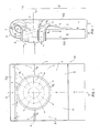
- the illustrated outlet housing for a turbomachine contains a body 01 which is rectangular in elevation and a circular diffuser d.
- the circular diffuser d consists of a trumpet-shaped jacket tube p open at the rear and a core j with a widened end part.
- the opening of the casing tube p is larger than the broadening of the core j, so that the circular cross-section of the diffuser d, which is delimited by both, widens towards the rear.
- the widened end of the core j is connected to the inside of the rear wall 100 of the body 01.
- the body 01 of the outlet housing is only supposed to be distributed vertically on the upper part H and the lower part D.
- the dividing line 14 between the upper part H and the lower part D runs below parallel or in alignment with the transverse axis z of the diffuser d.
- This assumed dividing line is an extension of the fictitious dividing plane between the proportion of steam flowing through the diffuser d into a straight duct I and the quantity of steam flowing into a circulation duct II.
- a distribution of the steam flow exists in every diffuser of flow machines of this type.
- the length D of the lower part D of the body 01 is divided by a partition 8 into two equal halves, ie into a rear section Z and a front section P.
- the straight channel I is accommodated in such a way that a rear oblique wall 4 is connected to the lower edge d2 of the diffuser d, which begins at the dividing line 14 and leads to the dividing wall 8.
- the circulation channel II begins in the upper part of the Kör pers 01, the outer cylinder wall 5 being connected to its end wall 100, the bending diameter of which corresponds to the sum of the width of the rear and front sections Z, P.
- the cylinder wall 5 merges into the front wall 200 of the body 01.
- the inner jacket of the circulation channel II forms a convex wall 7, which begins in the dividing line 14 and is connected to the upper end edge d1 of the diffuser d.
- 3 and 4 are in the straight channel I and the circulation channel II, in the immediate vicinity of the transverse axis z of the diffuser d, ie in the dividing line 14, two common edges 12, 13 of a first distributor 1 and a second Distributor 2 housed vertically and against each other and connected there to the outer jacket p of the circular diffuser d.
- These distributors 1, 2 are connected to the side walls 3, 6 via outer edges.
- the first and the second distributors 1, 2 are arcuate concave to the vertical axis x of the body 01.
- the steam flow from the last stage of the turbomachine enters the circular diffuser d and divides into a back through the straight channel 100 z. B. to the capacitors flowing lower part and in an upper partial flow, which is turned by the upper edge d1 of the diffuser, the convex wall 7 and the outer cylinder wall 7 and then guided along the casing tube p into the circulation channel II. Both steam parts then flow in the same direction in channels I and II.
- the distribution of the steam flow on the upper and lower flow is supported by distributors 1 and 2, on the surfaces of which the steam flows smoothly and does not form any eddies.
- the rear sloping wall 4 also essentially follows the streamlines of the steam and supports its uniform, continuous flow.
- the front sloping wall 11 in the circulation channel serves the same purpose.
- the two streamlined partitions 9 eliminate the risk of swirling in the area behind the lower edge d2 of the diffuser d and their streamlined shape also improves the swirl-free continuous steam flow.
- the baffles 10 reduce the swirl of the fluid by dividing the flow width into several narrower flows. The use of guide elements and / or partitions is matched to the characteristics of the respective turbomachine.
Abstract
Description
Die Erfindung betrifft ein Auslaßgehäuse einer Strömungsmaschine, in welchem sich eine axial gerichtete Einströmung in eine zur Maschinenachse senkrechte Ausströmung ändert. Die Erfindung ist besonders für Auslaßgehäuse von Dampfturbinen geeignet, die zwischen der letzten Stufe der Dampfturbine und dem Kondensator angeordnet sind.The invention relates to an outlet housing of a turbomachine, in which an axially directed inflow changes into an outflow perpendicular to the machine axis. The invention is particularly suitable for outlet casings of steam turbines which are arranged between the last stage of the steam turbine and the condenser.
Zu der Dampfabführung oder eines anderen Treibmittels aus der letzten Stufe einer Strömungsmaschine, z. B. einer Dampfturbine in die Kondensatoren, werden Auslaßgehäuse eingesetzt, die einen achssymmetrischen Diffusor und ein voluminöses Gehäuse enthalten, das in einen Einlaßstutzen des Kondensators übergeht. Das Gehäuse enthält eine Zylinderwand, deren Mantellinien zur Maschinenachse parallel sind. Es wurde festgestellt, daß das strömende Medium die Gehäusewände nicht glatt umströmt, sondern umfangreiche Wirbel entstehen, was zu erheblichen Energieverlusten führt.To evacuate steam or another blowing agent from the last stage of a turbomachine, e.g. B. a steam turbine in the condensers, outlet housings are used which contain an axisymmetric diffuser and a voluminous housing which merges into an inlet port of the condenser. The housing contains a cylinder wall, the surface lines of which are parallel to the machine axis. The flowing medium was found to be the Housing walls do not flow smoothly, but extensive vortices arise, which leads to considerable energy losses.
Ein anderes bekanntes Auslaßgehäuse weist zwei gegenüberliegende Austritte auf, durch welche der Dampf in zwei selbständige Kondensatoren strömt. In diesem Auslaßgehäuse ergeben sich geringere Energieverluste, aber für den Preis eines beträchtlichen Aufwandes durch die benötigten zwei Kondensatoren und deren Unterbringung im Maschinensaal.Another known outlet housing has two opposite outlets through which the steam flows into two independent condensers. This outlet housing results in lower energy losses, but for the price of a considerable outlay due to the two capacitors required and their accommodation in the machine room.
Aufgabe der Erfindung ist es, ein Auslaßgehäuse für Strömungsmaschinen zu schaffen, das bei relativ geringem technischen Aufwand verminderte Energieverluste gewährleistet.The object of the invention is to provide an outlet housing for turbomachines which ensures reduced energy losses with relatively little technical effort.
Diese Aufgabe wird durch die im Patentanspruch 1 angegebenen Merkmale gelöst.This object is achieved by the features specified in
Das erfindungsgemäße Auslaßgehäuse für Strömungsmaschinen enthält einen Körper, einen kreisförmigen Diffusor, Wände und Scheidewände. Der Körper umfaßt einen geraden Kanal, durch welchen etwa eine Dampfhälfte strömt, und einen Umführungskanal konstanter Breite, welcher den restlichen Dampfstrom um den kreisförmigen Diffusor in dieselbe Richtung führt, in welcher der Dampf in dem geraden Kanal strömt. Der gerade Kanal beginnt im Einklang mit der Strömung durch den kreisförmigen Diffusor an der Stelle unmittelbar hinter der Querachse des Diffusors und führt in Richtung von seiner Mitte zu dem Unterteil des Körpers und nimmt den hinteren Abschnitt dieses Unterteils des Körpers ein. Der Umführungskanal beginnt neben dem geraden Kanal am Ende des Diffusors und führt in einem nach oben und entgegen der Strömungsrichtung im Diffusor verlaufenden Bogen in einen geraden Kanalabschnitt, der in einen gemeinsamen quer zur Maschinenachse angeordneten Abströmkanal ausmündet. Der Außenmantel des Umlaufkanals bildet also einen Teil des Oberteils der Rückwand des Gehäusekörpers, an welche die äußere Zylinderwand anschließt, welche sich mit der Vorderwand des Gehäusekörpers verbindet. Den Innenmantel des Umlaufkanals bildet in dem Oberteil des Gehäusekörpers eine konvexe Wand, welche an den oberen Rand des Diffusormantels anschließt und in eine schräge Wand übergeht, welche allmählich zurückführt und in unmittelbarer Nähe der Querachse des Diffusors an eine vertikale Scheidewand im Unterteil des Gehäusekörpers anschließt, welche den vorderen Abschnitt des Gehäusekörpers vom hinteren trennt. Den Außenmantel des geraden Kanals bildet die Rückwand des Unterteils des Gehäusekörpers und seinen Innenmantel bildet die hintere schräge Wand, welche an den unteren Rand des Diffusormantels in der Nähe der Querebene des Diffusors beginnt und an den gegenüberliegenden Rand der Trenn- bzw. Scheidewand angeschlossen ist, welche den hinteren vom vorderen Abschnitt des Gehäusekörpers trennt. Den Seitenmantel des geraden Kanals und des Umlaufkanals bildet die rechte und linke Seitenwand des Gehäusekörpers.The outlet housing for turbomachines according to the invention contains a body, a circular diffuser, walls and partitions. The body includes a straight channel through which approximately one half of the steam flows and a bypass channel of constant width which guides the remaining steam flow around the circular diffuser in the same direction in which the steam flows in the straight channel. The straight channel begins in accordance with the flow through the circular diffuser at the location immediately behind the transverse axis of the diffuser and leads towards its center towards the lower part of the body and occupies the rear portion of this lower part of the body. The bypass channel begins next to the straight channel at the end of the diffuser and leads in an upward direction and against the direction of flow in the diffuser Elbow in a straight channel section, which opens into a common discharge channel arranged transversely to the machine axis. The outer jacket of the circulation channel thus forms part of the upper part of the rear wall of the housing body, to which the outer cylinder wall connects, which connects to the front wall of the housing body. The inner jacket of the circulation channel forms a convex wall in the upper part of the housing body, which connects to the upper edge of the diffuser jacket and merges into an inclined wall, which gradually leads back and connects to a vertical partition in the lower part of the housing body in the immediate vicinity of the transverse axis of the diffuser, which separates the front portion of the housing body from the rear. The outer casing of the straight channel forms the rear wall of the lower part of the housing body and its inner casing forms the rear oblique wall, which begins at the lower edge of the diffuser casing near the transverse plane of the diffuser and is connected to the opposite edge of the partition or partition, which separates the rear section from the front section of the housing body. The side jacket of the straight channel and the circulation channel forms the right and left side wall of the housing body.
Eine Ausgestaltung der Erfindung enthält Teiler in dem geraden Kanal und dem Umlaufkanal, wobei die gemeinsamen Kanten der ersten Verteiler miteinander und auch die gemeinsamen Kanten der zweiten Verteiler miteinander verbunden sind. Diese Verbindungen sind an den gegenüberliegenden Stellen des Diffusormantels und zwar waagerecht in unmittelbarer Nähe der Querachse des Diffusors angeschlossen. Die Verteiler sind mit ihren Außenkanten mit den Seitenwänden des Gehäusekörpers so verbunden, daß die einzelnen Verteiler hinsichtlich der Vertikalachse dieses Körpers konkav sind.One embodiment of the invention contains dividers in the straight channel and the circulation channel, the common edges of the first manifold being connected to one another and also the common edge of the second distributor being connected to one another. These connections are connected at the opposite points of the diffuser jacket, namely horizontally in the immediate vicinity of the transverse axis of the diffuser. The distributors are connected with their outer edges to the side walls of the housing body so that the individual distributors are concave with respect to the vertical axis of this body.
Bei einer Weiterbildung der Erfindung ist im Umlaufkanal an gegenüberliegenden Stellen des Diffusormantels unmittelbar hinter seiner Querachse ein Paar von stromlinienförmigen Leit- bzw. Scheidewänden waagerecht angeordnet, deren entgegengesetzte Kanten miteinander in der Vertikalachse des Gehäusekörpers verbunden sind. Zweckmäßig können zwischen die stromlinienförmigen Scheidewände und die Seitenwände des Körpers des Auslaßgehäuses die vertikalen Ablenkbleche eingelegt sein.In a further development of the invention, a pair of streamlined baffles or dividing walls are arranged horizontally in the circulation channel at opposite points of the diffuser jacket immediately behind its transverse axis, the opposite edges of which are connected to one another in the vertical axis of the housing body. The vertical baffles can expediently be inserted between the streamlined partition walls and the side walls of the body of the outlet housing.
Ein Vorteil des Auslaßgehäuses gemäß der Erfindung liegt in der wesentlichen Verminderung der Nachlauf- und Wirbel-Bereiche, was zu einer wesentlichen Minderung der Energieverluste der Strömungsmaschine führt. Ein weiterer Vorteil liegt darin, daß die ursprünglichen Gehäuseabmessungen und seine Außengestalt in etwa erhalten bleiben. Das erfindungsgemäße Gehäuse wird aus den formgestalteten Blechen hergestellt.An advantage of the outlet housing according to the invention is the substantial reduction in the wake and swirl areas, which leads to a substantial reduction in the energy losses of the turbomachine. Another advantage is that the original dimensions of the housing and its external shape are roughly preserved. The housing according to the invention is produced from the shaped sheets.
Im folgenden werden bevorzugte Ausführungsbeispiele der Erfindung anhand der Zeichnung ausführlich beschrieben. Es zeigen:
- Fig. 1 ein Auslaßgehäuse schematisch im vertikalen Axialschnitt,
- Fig. 2 das Auslaßgehäuse nach Fig. 1 in schematischer Seitenansicht,
- Fig. 3 ein anderes Auslaßgehäuse mit Hilfsscheidewänden im Axialschnitt,
- Fig. 4 einen schematischen Aufriß des so ausgebildeten Auslaßgehäuses in dem angedeuteten Schnitt.
- 1 is an outlet housing schematically in vertical axial section,
- 2 is a schematic side view of the outlet housing according to FIG. 1,
- 3 shows another outlet housing with auxiliary dividing walls in axial section,
- Fig. 4 is a schematic elevation of the outlet housing thus formed in the indicated section.
Die dargestellten Auslaßgehäuse für eine Strömungsmaschine enthalten einen im Aufriß rechteckigen Körper 01 und einen kreisförmigen Diffusor d. Der kreisförmige Diffusor d besteht aus einem trompetenförmigen hinten offenen Mantelrohr p und aus einem Kern j mit verbreitertem Endteil. Die Öffnung des Mantelrohrs p ist größer als die Verbreiterung des Kerns j, so daß sich der von beiden begrenzte Kreisringquerschnitt des Diffusors d nach hinten verbreitert. Der Kern j ist mit seinem verbreiterten Ende an die Innenseite der Rückwand 100 des Körpers 01 angeschlossen. Den Körper 01 des Auslaßgehäuses ist möglich nur angenommen auf den Oberteil H und den Unterteil D vertikal zu verteilen. Die Trennungslinie 14 zwischen dem Oberteil H und dem Unterteil D verläuft unterhalb parallel oder in Flucht zur Querachse z des Diffusors d. Diese angenommene Trennungslinie ist eine Verlängerung der fiktiven Trennungsebene zwischen dem durch den Diffusor d in einen geraden Kanal I einströmenden Dampfanteil und der in einen Umlaufkanal II einströmenden Dampfmenge. Eine Verteilung der Dampfströmung existiert in jedem Diffusor von Strömungsmaschinen dieses Typs. In seiner Länge ist der Unterteil D des Körpers 01 durch eine Trennwand 8 in zwei gleiche Hälften, d. h. in einen Hinterabschnitt Z und einen Vorderabschnitt P geteilt. Im Hinterabschnitt Z ist der gerade Kanal I so untergebracht, daß an dem unteren Rand d2 des Diffusors d eine hintere schräge Wand 4 angeschlossen ist, die an der Trennungslinie 14 beginnt und zur Trennwand 8 führt. Der Umlaufkanal II beginnt im Oberteil des Kör pers 01, wobei an seine Endwand 100 die äußere Zylinderwand 5 angeschlossen ist, deren Biegungsdurchmesser der Summe der Breite des Hinter- und Vorderabschnitts Z, P entspricht. Die Zylinderwand 5 geht in die Vorderwand 200 des Körpers 01 über. Den Innenmantel des Umlaufkanals II bildet eine konvexe Wand 7, die in der Trennungslinie 14 beginnt und an die obere Endkante d1 des Diffusors d angeschlossen ist. Ihre Abrundung folgt im wesentlichen der Abrundung der äußeren Zylinderwand 5 bis zu dem Umfang des Mantelrohrs p des Diffusors d, wo sie an eine vordere schräge Wand 11 angeschlossen ist, welche bis zu der Trennungslinie 14 ab steigt und hier mit der Anfangskante der Leit- bzw. Trennwand 8 verbunden ist.The illustrated outlet housing for a turbomachine contains a
Bei der Ausführung nach Fig. 3 und 4 sind in den geraden Kanal I und den Umlaufkanal II, und zwar in unmittelbarer Nähe der Querachse z des Diffusors d, d. h. in der Trennungslinie 14 zwei gemeinsame Kanten 12, 13 eines ersten Verteilers 1 und eines zweiten Verteilers 2 vertikal und gegeneinander untergebracht und dort an den äußeren Mantel p des kreisförmigen Diffusors d angeschlossen. Über äußere Kanten sind diese Verteiler 1, 2 an die Seitenwände 3, 6 angeschlossen. Die ersten und die zweiten Verteiler 1, 2 sind zur Vertikalachse x des Körpers 01 bogenförmig konkav. An den diametral gegenüberliegenden Stellen des Mantelrohrs p sind in der Nähe der Querachse z des Körpers 01 die Enden eines Paares von stromlinienförmigen Leit- bzw. Scheidewänden 9 angeschlossen, welche sich in Richtung der Dampfströmung stromlinienförmig aneinander annähern, bis sie in der Vertikalachse x des Körpers 01 zusammentreffen. Zwischen der Außenfläche der beiden Scheidewände 9 und den Seitenwänden 3, 6 sind im Umlaufkanal II zwei Paare von etwa vertikalen Leitblechen 10 angeordnet, deren Innenwände etwa dem Verlauf der stromlinienförmigen Scheidewände 9 folgen, wobei sich jedoch die Durchströmquerschnitte der von ihnen und den Wänden 9, 3, 6 begrenzten Strömungskanäle gleichförmig erweitern.3 and 4 are in the straight channel I and the circulation channel II, in the immediate vicinity of the transverse axis z of the diffuser d, ie in the dividing line 14, two
Der Dampfstrom aus der letzten Stufe der Strömungsmaschine tritt in den kreisförmigen Diffusor d ein und teilt sich an dessen Rückwand in einen durch den geraden Kanal 100 z. B. zu den Kondensatoren strömenden unteren Teil sowie in einen oberen Teilstrom, welcher durch den oberen Rand d1 des Diffusors, die konvexe Wand 7 und die äußere Zylinderwand 7 umgewendet und dann längs des Mantelrohrs p in den Umlaufkanal II geführt wird. Beide Dampfteile strömen dann in gleicher Richtung in den Kanälen I und II. Die Verteilung des Dampfstroms auf den oberen und den unteren Strom unterstützen die Verteiler 1 und 2, an deren Oberflächen der Dampf glatt abströmt und keine Wirbel bildet. Auch die hintere schräge Wand 4 folgt im wesentlichen den Stromlinien des Dampfes und unterstützt seine gleichförmige kontinuierliche Strömung. Die vordere schräge Wand 11 im Umlaufkanal dient demselben Zweck. Die beiden stromlinienförmigen Scheidewände 9 beseitigen die Wirbelgefahr im Bereich hinter dem unteren Rand d2 des Diffusors d und ihre Stromliniengestalt verbessert ebenfalls die wirbelfreie kontinuierliche Dampfströmung. Schließlich vermindern die Leitbleche 10 durch Aufteilung der Strombreite auf mehrere engere Ströme die Wirbelung des Strömungsmittels. Die Anwendung von Leitelementen und/oder Scheidewänden wird auf die Charakteristiken der jeweiligen Strömungsmaschine abgestimmt.The steam flow from the last stage of the turbomachine enters the circular diffuser d and divides into a back through the straight channel 100 z. B. to the capacitors flowing lower part and in an upper partial flow, which is turned by the upper edge d1 of the diffuser, the convex wall 7 and the outer cylinder wall 7 and then guided along the casing tube p into the circulation channel II. Both steam parts then flow in the same direction in channels I and II. The distribution of the steam flow on the upper and lower flow is supported by
Claims (5)
dadurch gekennzeichnet,
daß an das erweiterte Ende des Diffusors (d) zwei Abströmkanäle (I, II) angeschlossen sind, von denen der hintere von der Gehäuserückwand (100) begrenzte Abströmkanal (I) geradlinig und quer zur Maschinenlängsachse (0) verläuft und der vordere Abströmkanal (II) über einen entgegen der Strömungsrichtung im Diffusor verlaufenden Bogenabschnitt (IIa) an den ersten Abströmkanal angeschlossen ist.1. outlet housing for fluid-flow machines consisting of a housing body (01), a circular diffuser (d) and possibly guide walls,
characterized,
that two outflow channels (I, II) are connected to the extended end of the diffuser (d), of which the rear outflow channel (I) bounded by the rear wall of the housing (100) runs in a straight line and transversely to the machine longitudinal axis (0) and the front outflow channel (II ) is connected to the first outflow channel via an arc section (IIa) running counter to the flow direction in the diffuser.
dadurch gekennzeichnet,
daß der Gehäusekörper (01) in den geraden Abströmkanal (I) und den Umlaufkanal (II) aufgeteilt ist, wobei der gerade Abströmkanal (I) im wesentlichen von der Querachse (z) des kreisförmigen Diffusors (d) und den Hinterabschnitt (Z) des Unterteils des Gehäusekörpers (01) begrenzt ist, wogegen der Umlaufkanal (II) von konstanter Breite im wesentlichen durch die Querachse (z) des Diffusors (d), den Oberteil (H) und den Vorderabschnitt (P) des Gehäusekörpers (01) so begrenzt ist, daß sein Außenmantel im Oberteil (H) des Gehäusekörpers (01) die äußere Zylinderwand (5) als Fortsetzung der Fläche der geraden Rückwand (100) des Gehäusekörpers (01) und sowohl im Oberteil (H) als auch im Unterteil (D) des Gehäusekörpers (01) die Vorderwand (200) des Gehäusekörpers (01) bilden, und dabei sein Innenmantel in dem Oberteil (H) des Gehäusekörpers (01) eine konvexe Wand (7) bildet, welche an den verbreiterten oberen Rand (d1) des Diffusormantels (p) angeschlossen ist, welche an eine vordere schräge Wand (11) anknüpft, die im wesentlichen in der Querachse (z) des Diffusors (d) an der vertikalen Scheidewand (8) des Unterteils (D) angeschlossen ist, wobei der Außenmantel des geraden Abströmkanals (I)von der Rückwand (100) des Gehäusekörpers (01) und sein Innenmantel von der hinteren schrägen Wand (4) gebildet ist, welche an den unteren Rand (d2) des Mantels (p) des Diffusors (d) angeschlossen ist und welche mittels ihres gegenüberliegenden Randes an der Scheidewand (8) angeschlossen ist, die zwischen dem Hinterabschnitt (Z) und dem Vorderabschnitt (P) des Körpers (01) des Auslaßgehäuses untergebracht ist.2. outlet housing according to claim 1,
characterized,
that the housing body (01) is divided into the straight outflow channel (I) and the circulation channel (II), the straight outflow channel (I) essentially from the transverse axis (z) of the circular diffuser (d) and the rear section (Z) of the Lower part of the housing body (01) is limited, whereas the circulation channel (II) of constant Width is essentially limited by the transverse axis (z) of the diffuser (d), the upper part (H) and the front section (P) of the housing body (01) so that its outer jacket in the upper part (H) of the housing body (01) the outer Cylinder wall (5) as a continuation of the surface of the straight rear wall (100) of the housing body (01) and form the front wall (200) of the housing body (01) both in the upper part (H) and in the lower part (D) of the housing body (01), and thereby its inner casing in the upper part (H) of the housing body (01) forms a convex wall (7) which is connected to the widened upper edge (d1) of the diffuser casing (p), which connects to a front inclined wall (11) which is connected essentially in the transverse axis (z) of the diffuser (d) to the vertical partition (8) of the lower part (D), the outer jacket of the straight outflow channel (I) from the rear wall (100) of the housing body (01) and its inner jacket is formed by the rear sloping wall (4), which on de n lower edge (d2) of the jacket (p) of the diffuser (d) is connected and which is connected by means of its opposite edge to the partition (8) which is between the rear section (Z) and the front section (P) of the body (01 ) of the outlet housing.
dadurch gekennzeichnet,
daß in den geraden Abströmkanal (I) und den Umlaufkanal (II) erste und zweite Verteiler (1, 2) eingelegt sind, wobei die ersten Verteiler an einer Seite in einer gemeinsamen Kante (12) und die zweiten Verteiler an der anderen Seite in je einer gemeinsamen Kante (13) mitein ander verbunden sind, welche an den gegenüberliegenden Seiten des Diffusormantels (p) waagerecht und in unmittelbarer Nähe der Querachse (z) angeordnet sind, und wobei die Außenkanten der ersten Verteiler (1) an der einen Seitenwand (3) und die Außenkanten der zweiten Verteiler (2) an der anderen Seitenwand (6) des Gehäusekörpers (01) so angeschlossen sind, daß die einzelnen Verteiler (1, 2) hinsichtlich der Vertikalachse (x) dieses Gehäusekörpers (01) konkav sind.3. outlet housing according to claim 1 or 2,
characterized,
that in the straight outflow channel (I) and the circulation channel (II) first and second distributors (1, 2) are inserted, the first distributors on one side in a common edge (12) and the second distributors on the other side in each case a common edge (13) connected, which are arranged on the opposite sides of the diffuser shell (p) horizontally and in the immediate vicinity of the transverse axis (z), and wherein the outer edges of the first distributor (1) on one side wall (3) and the outer edges of the second distributor (2) are connected to the other side wall (6) of the housing body (01) in such a way that the individual distributors (1, 2) are concave with respect to the vertical axis (x) of this housing body (01).
dadurch gekennzeichnet,
daß im Umlaufkanal (II) an den gegenüberliegenden Seiten des Diffusormantels (p) unmittelbar hinter seiner Querachse (z) stromlinienförmige Leit- bzw. Scheidewände (9) waagerecht angeschlossen sind, deren entgegengesetzte Kanten miteinander in der Vertikalachse (x) des Gehäusekörpers (01) verbunden sind.4. outlet housing according to claim 1 to 3,
characterized,
that in the circulation channel (II) on the opposite sides of the diffuser jacket (p) directly behind its transverse axis (z) streamlined guiding or dividing walls (9) are connected horizontally, the opposite edges of which are in the vertical axis (x) of the housing body (01) are connected.
dadurch gekennzeichnet,
daß zwischen die Außenfläche der stromlinienförmigen Scheidewände (9) und die Seitenwände (3, 6) des Gehäusekörpers (01) etwa vertikale Ablenkbleche (10) eingelegt sind.5. outlet housing according to claim 1 to 4,
characterized,
that between the outer surface of the streamlined partition walls (9) and the side walls (3, 6) of the housing body (01) approximately vertical baffles (10) are inserted.
Applications Claiming Priority (2)
| Application Number | Priority Date | Filing Date | Title |
|---|---|---|---|
| CS392788A CS272676B1 (en) | 1988-06-07 | 1988-06-07 | Outlet branch for bladed machine |
| CS3927/88 | 1988-06-07 |
Publications (2)
| Publication Number | Publication Date |
|---|---|
| EP0345700A1 true EP0345700A1 (en) | 1989-12-13 |
| EP0345700B1 EP0345700B1 (en) | 1992-08-26 |
Family
ID=5380750
Family Applications (1)
| Application Number | Title | Priority Date | Filing Date |
|---|---|---|---|
| EP19890110149 Expired - Lifetime EP0345700B1 (en) | 1988-06-07 | 1989-06-05 | Turbo machine exhaust casing |
Country Status (3)
| Country | Link |
|---|---|
| EP (1) | EP0345700B1 (en) |
| CS (1) | CS272676B1 (en) |
| DE (1) | DE58902123D1 (en) |
Cited By (10)
| Publication number | Priority date | Publication date | Assignee | Title |
|---|---|---|---|---|
| EP0558652A1 (en) * | 1990-11-21 | 1993-09-08 | Norlock Technologies, Inc. | Method and apparatus for enhancing gas turbo machinery flow |
| WO1997016628A2 (en) * | 1995-10-31 | 1997-05-09 | Siemens Aktiengesellschaft | Transition element between components of the flue gas duct of a gas turbine |
| FR2757210A1 (en) * | 1996-12-12 | 1998-06-19 | Hispano Suiza Sa | Centrifugal exhaust for gas turbine |
| WO1998055739A1 (en) * | 1997-06-05 | 1998-12-10 | Abb Stal Ab | An outlet device for a flow machine |
| WO1999020874A1 (en) * | 1997-10-17 | 1999-04-29 | Zakrytoe Aktsionernoe Obschestvo 'entek' | Exhaust duct for a steam turbine |
| WO1999051858A1 (en) | 1998-04-06 | 1999-10-14 | Siemens Aktiengesellschaft | Steam turbine |
| US6062814A (en) * | 1995-10-31 | 2000-05-16 | Siemens Aktiengesellschaft | Transition element between components of a flue-gas duct of a gas turbine |
| JP2006307738A (en) * | 2005-04-28 | 2006-11-09 | Toshiba Corp | Steam turbine |
| EP1892384A1 (en) * | 2006-08-25 | 2008-02-27 | Siemens Aktiengesellschaft | Diffuser for a steam turbine |
| EP1992789A1 (en) * | 2007-05-18 | 2008-11-19 | ABB Turbo Systems AG | Exhaust gas turbine casing comprising a support element |
Families Citing this family (1)
| Publication number | Priority date | Publication date | Assignee | Title |
|---|---|---|---|---|
| CZ302698B6 (en) * | 2009-05-19 | 2011-09-07 | Ceské vysoké ucení technické v Praze | Transition piece of bladed machine |
Citations (4)
| Publication number | Priority date | Publication date | Assignee | Title |
|---|---|---|---|---|
| FR1110063A (en) * | 1953-10-23 | 1956-02-06 | Licentia Gmbh | Annular diffuser placed before the steam or gas exhaust chamber of a steam or gas turbine |
| US3149470A (en) * | 1962-08-29 | 1964-09-22 | Gen Electric | Low pressure turbine exhaust hood |
| FR2381907A1 (en) * | 1977-02-24 | 1978-09-22 | Maschf Augsburg Nuernberg Ag | Gas transfer duct for continuous flow engine - has diffuser and trunking at right angles with curved sidewalls leading to heat exchanger |
| US4326832A (en) * | 1978-11-14 | 1982-04-27 | Tokyo Shibaura Denki Kabushiki Kaisha | Exhaust outer casing |
-
1988
- 1988-06-07 CS CS392788A patent/CS272676B1/en unknown
-
1989
- 1989-06-05 EP EP19890110149 patent/EP0345700B1/en not_active Expired - Lifetime
- 1989-06-05 DE DE8989110149T patent/DE58902123D1/en not_active Expired - Fee Related
Patent Citations (4)
| Publication number | Priority date | Publication date | Assignee | Title |
|---|---|---|---|---|
| FR1110063A (en) * | 1953-10-23 | 1956-02-06 | Licentia Gmbh | Annular diffuser placed before the steam or gas exhaust chamber of a steam or gas turbine |
| US3149470A (en) * | 1962-08-29 | 1964-09-22 | Gen Electric | Low pressure turbine exhaust hood |
| FR2381907A1 (en) * | 1977-02-24 | 1978-09-22 | Maschf Augsburg Nuernberg Ag | Gas transfer duct for continuous flow engine - has diffuser and trunking at right angles with curved sidewalls leading to heat exchanger |
| US4326832A (en) * | 1978-11-14 | 1982-04-27 | Tokyo Shibaura Denki Kabushiki Kaisha | Exhaust outer casing |
Cited By (18)
| Publication number | Priority date | Publication date | Assignee | Title |
|---|---|---|---|---|
| EP0558652A4 (en) * | 1990-11-21 | 1994-01-19 | Thomas R. Norris | |
| EP0558652A1 (en) * | 1990-11-21 | 1993-09-08 | Norlock Technologies, Inc. | Method and apparatus for enhancing gas turbo machinery flow |
| US6062814A (en) * | 1995-10-31 | 2000-05-16 | Siemens Aktiengesellschaft | Transition element between components of a flue-gas duct of a gas turbine |
| WO1997016628A2 (en) * | 1995-10-31 | 1997-05-09 | Siemens Aktiengesellschaft | Transition element between components of the flue gas duct of a gas turbine |
| WO1997016628A3 (en) * | 1995-10-31 | 1997-07-03 | Siemens Ag | Transition element between components of the flue gas duct of a gas turbine |
| FR2757210A1 (en) * | 1996-12-12 | 1998-06-19 | Hispano Suiza Sa | Centrifugal exhaust for gas turbine |
| WO1998055739A1 (en) * | 1997-06-05 | 1998-12-10 | Abb Stal Ab | An outlet device for a flow machine |
| US6231304B1 (en) | 1997-06-05 | 2001-05-15 | Abb Stal Ab | Outlet device for a flow machine |
| WO1999020874A1 (en) * | 1997-10-17 | 1999-04-29 | Zakrytoe Aktsionernoe Obschestvo 'entek' | Exhaust duct for a steam turbine |
| CN1089136C (en) * | 1997-10-17 | 2002-08-14 | Entek股份有限公司 | Exhaust duct for steam turbine |
| WO1999051858A1 (en) | 1998-04-06 | 1999-10-14 | Siemens Aktiengesellschaft | Steam turbine |
| JP2002510769A (en) * | 1998-04-06 | 2002-04-09 | シーメンス アクチエンゲゼルシヤフト | Steam turbine |
| JP2006307738A (en) * | 2005-04-28 | 2006-11-09 | Toshiba Corp | Steam turbine |
| JP4557787B2 (en) * | 2005-04-28 | 2010-10-06 | 株式会社東芝 | Steam turbine |
| EP1892384A1 (en) * | 2006-08-25 | 2008-02-27 | Siemens Aktiengesellschaft | Diffuser for a steam turbine |
| EP1992789A1 (en) * | 2007-05-18 | 2008-11-19 | ABB Turbo Systems AG | Exhaust gas turbine casing comprising a support element |
| WO2008142044A2 (en) * | 2007-05-18 | 2008-11-27 | Abb Turbo Systems Ag | Turbine housing |
| WO2008142044A3 (en) * | 2007-05-18 | 2009-11-19 | Abb Turbo Systems Ag | Gas outlet housing of an exhaust turbine with a support element |
Also Published As
| Publication number | Publication date |
|---|---|
| DE58902123D1 (en) | 1992-10-01 |
| CS272676B1 (en) | 1991-02-12 |
| EP0345700B1 (en) | 1992-08-26 |
| CS392788A1 (en) | 1990-06-13 |
Similar Documents
| Publication | Publication Date | Title |
|---|---|---|
| DE60016937T2 (en) | ANTI-SWIVEL SYSTEM FOR CIRCULAR COMPRESSORS | |
| EP1223308B1 (en) | Turbomachine component | |
| DE2934041C2 (en) | Controlled exhaust gas turbocharger turbine | |
| DE3534905A1 (en) | HOLLOW TURBINE BLADE COOLED BY A FLUID | |
| AT2490U1 (en) | COOLER ARRANGEMENT FOR A CHARGED INTERNAL COMBUSTION ENGINE WITH EXHAUST GAS RECIRCULATION | |
| EP2495425A2 (en) | Jet engine device with a bypass flow channel | |
| DE2942143A1 (en) | HOUSING FOR A TURBINE WHEEL | |
| EP0345700B1 (en) | Turbo machine exhaust casing | |
| EP0799973A1 (en) | Wall contour for an axial turbomachine | |
| DE3421792A1 (en) | RADIAL TURBINE WITH VARIABLE CAPACITY, WITH A SWIVELING TONGUE PART | |
| DE2632155A1 (en) | FAN GAS TURBINE JET | |
| WO1989007194A1 (en) | Turbine for an exhaust gas turbocharger | |
| WO2016096813A1 (en) | Air pipe for an intake tract of an internal combustion engine, in particular of a motor vehicle | |
| DE3121341C2 (en) | Exhaust pipe system between a multi-cylinder internal combustion engine charged according to the stagnation principle and an exhaust gas turbocharger | |
| DE602004006035T2 (en) | Cooling device for turbine disks | |
| DE3203342C2 (en) | Air duct for supplying compressed air in a gas turbine system | |
| DE10145489B4 (en) | Arrangement for mixing two originally separately guided fluid streams in a two-circuit jet engine | |
| DE3614467C2 (en) | Bladed grille for gas turbine engines | |
| DE3916008C1 (en) | ||
| DE2708809C2 (en) | ||
| DE1601627C3 (en) | Cooled blade for a flow machine | |
| DE3630488A1 (en) | Intake pipe of adjustable length for an internal combustion engine | |
| DE10060705A1 (en) | Motor-independent heater for a motor vehicle | |
| EP1353054B1 (en) | Turboprop engine | |
| EP0086467A1 (en) | Scroll for a radial turbine |
Legal Events
| Date | Code | Title | Description |
|---|---|---|---|
| PUAI | Public reference made under article 153(3) epc to a published international application that has entered the european phase |
Free format text: ORIGINAL CODE: 0009012 |
|
| AK | Designated contracting states |
Kind code of ref document: A1 Designated state(s): CH DE FR GB IT LI SE |
|
| 17P | Request for examination filed |
Effective date: 19900208 |
|
| 17Q | First examination report despatched |
Effective date: 19910318 |
|
| GRAA | (expected) grant |
Free format text: ORIGINAL CODE: 0009210 |
|
| AK | Designated contracting states |
Kind code of ref document: B1 Designated state(s): CH DE FR GB IT LI SE |
|
| ITF | It: translation for a ep patent filed |
Owner name: ING. C. GREGORJ S.P.A. |
|
| GBT | Gb: translation of ep patent filed (gb section 77(6)(a)/1977) | ||
| REF | Corresponds to: |
Ref document number: 58902123 Country of ref document: DE Date of ref document: 19921001 |
|
| ET | Fr: translation filed | ||
| PLBE | No opposition filed within time limit |
Free format text: ORIGINAL CODE: 0009261 |
|
| STAA | Information on the status of an ep patent application or granted ep patent |
Free format text: STATUS: NO OPPOSITION FILED WITHIN TIME LIMIT |
|
| 26N | No opposition filed | ||
| EAL | Se: european patent in force in sweden |
Ref document number: 89110149.5 |
|
| PGFP | Annual fee paid to national office [announced via postgrant information from national office to epo] |
Ref country code: GB Payment date: 19960528 Year of fee payment: 8 |
|
| PGFP | Annual fee paid to national office [announced via postgrant information from national office to epo] |
Ref country code: FR Payment date: 19960611 Year of fee payment: 8 |
|
| PGFP | Annual fee paid to national office [announced via postgrant information from national office to epo] |
Ref country code: DE Payment date: 19960612 Year of fee payment: 8 |
|
| PGFP | Annual fee paid to national office [announced via postgrant information from national office to epo] |
Ref country code: SE Payment date: 19960619 Year of fee payment: 8 |
|
| PGFP | Annual fee paid to national office [announced via postgrant information from national office to epo] |
Ref country code: CH Payment date: 19960620 Year of fee payment: 8 |
|
| PG25 | Lapsed in a contracting state [announced via postgrant information from national office to epo] |
Ref country code: GB Free format text: LAPSE BECAUSE OF NON-PAYMENT OF DUE FEES Effective date: 19970605 |
|
| PG25 | Lapsed in a contracting state [announced via postgrant information from national office to epo] |
Ref country code: SE Effective date: 19970606 |
|
| PG25 | Lapsed in a contracting state [announced via postgrant information from national office to epo] |
Ref country code: LI Free format text: LAPSE BECAUSE OF NON-PAYMENT OF DUE FEES Effective date: 19970630 Ref country code: CH Free format text: LAPSE BECAUSE OF NON-PAYMENT OF DUE FEES Effective date: 19970630 |
|
| GBPC | Gb: european patent ceased through non-payment of renewal fee |
Effective date: 19970605 |
|
| REG | Reference to a national code |
Ref country code: CH Ref legal event code: PL |
|
| PG25 | Lapsed in a contracting state [announced via postgrant information from national office to epo] |
Ref country code: FR Free format text: LAPSE BECAUSE OF NON-PAYMENT OF DUE FEES Effective date: 19980227 |
|
| EUG | Se: european patent has lapsed |
Ref document number: 89110149.5 |
|
| PG25 | Lapsed in a contracting state [announced via postgrant information from national office to epo] |
Ref country code: DE Free format text: LAPSE BECAUSE OF NON-PAYMENT OF DUE FEES Effective date: 19980303 |
|
| REG | Reference to a national code |
Ref country code: FR Ref legal event code: ST |
|
| REG | Reference to a national code |
Ref country code: FR Ref legal event code: ST |
|
| PG25 | Lapsed in a contracting state [announced via postgrant information from national office to epo] |
Ref country code: IT Free format text: LAPSE BECAUSE OF NON-PAYMENT OF DUE FEES;WARNING: LAPSES OF ITALIAN PATENTS WITH EFFECTIVE DATE BEFORE 2007 MAY HAVE OCCURRED AT ANY TIME BEFORE 2007. THE CORRECT EFFECTIVE DATE MAY BE DIFFERENT FROM THE ONE RECORDED. Effective date: 20050605 |