EP0344569A2 - Appareil de commutation électronique notament interrupteur de proximité - Google Patents
Appareil de commutation électronique notament interrupteur de proximité Download PDFInfo
- Publication number
- EP0344569A2 EP0344569A2 EP89109202A EP89109202A EP0344569A2 EP 0344569 A2 EP0344569 A2 EP 0344569A2 EP 89109202 A EP89109202 A EP 89109202A EP 89109202 A EP89109202 A EP 89109202A EP 0344569 A2 EP0344569 A2 EP 0344569A2
- Authority
- EP
- European Patent Office
- Prior art keywords
- sleeve
- switching device
- electronic switching
- sleeve part
- plug
- Prior art date
- Legal status (The legal status is an assumption and is not a legal conclusion. Google has not performed a legal analysis and makes no representation as to the accuracy of the status listed.)
- Granted
Links
- 239000004033 plastic Substances 0.000 claims abstract description 17
- 229920003023 plastic Polymers 0.000 claims abstract description 17
- 239000000428 dust Substances 0.000 claims abstract description 7
- XLYOFNOQVPJJNP-UHFFFAOYSA-N water Substances O XLYOFNOQVPJJNP-UHFFFAOYSA-N 0.000 claims abstract description 7
- 238000001125 extrusion Methods 0.000 claims abstract description 5
- 238000005516 engineering process Methods 0.000 claims description 15
- 238000004023 plastic welding Methods 0.000 claims description 8
- 238000009413 insulation Methods 0.000 claims description 6
- 238000007789 sealing Methods 0.000 claims description 6
- 239000002184 metal Substances 0.000 claims description 5
- 230000003287 optical effect Effects 0.000 claims description 5
- 229920002492 poly(sulfone) Polymers 0.000 claims description 4
- 238000002347 injection Methods 0.000 description 3
- 239000007924 injection Substances 0.000 description 3
- 239000000463 material Substances 0.000 description 3
- 238000013459 approach Methods 0.000 description 2
- 230000001939 inductive effect Effects 0.000 description 2
- 239000004695 Polyether sulfone Substances 0.000 description 1
- 239000011324 bead Substances 0.000 description 1
- 239000002131 composite material Substances 0.000 description 1
- 239000012777 electrically insulating material Substances 0.000 description 1
- 238000000034 method Methods 0.000 description 1
- 230000036651 mood Effects 0.000 description 1
- 230000005693 optoelectronics Effects 0.000 description 1
- 229920006393 polyether sulfone Polymers 0.000 description 1
- 229920012287 polyphenylene sulfone Polymers 0.000 description 1
- 239000011347 resin Substances 0.000 description 1
- 229920005989 resin Polymers 0.000 description 1
- 238000002604 ultrasonography Methods 0.000 description 1
Images

Classifications
-
- H—ELECTRICITY
- H03—ELECTRONIC CIRCUITRY
- H03K—PULSE TECHNIQUE
- H03K17/00—Electronic switching or gating, i.e. not by contact-making and –breaking
- H03K17/94—Electronic switching or gating, i.e. not by contact-making and –breaking characterised by the way in which the control signals are generated
- H03K17/945—Proximity switches
-
- H—ELECTRICITY
- H01—ELECTRIC ELEMENTS
- H01H—ELECTRIC SWITCHES; RELAYS; SELECTORS; EMERGENCY PROTECTIVE DEVICES
- H01H9/00—Details of switching devices, not covered by groups H01H1/00 - H01H7/00
- H01H9/02—Bases, casings, or covers
- H01H9/04—Dustproof, splashproof, drip-proof, waterproof, or flameproof casings
-
- H—ELECTRICITY
- H01—ELECTRIC ELEMENTS
- H01H—ELECTRIC SWITCHES; RELAYS; SELECTORS; EMERGENCY PROTECTIVE DEVICES
- H01H9/00—Details of switching devices, not covered by groups H01H1/00 - H01H7/00
- H01H9/16—Indicators for switching condition, e.g. "on" or "off"
- H01H9/161—Indicators for switching condition, e.g. "on" or "off" comprising light emitting elements
Definitions
- the invention relates to an electronic switching device with an inner sleeve closed on one end face, a plug closing the inner sleeve on the open end face and an outer sleeve surrounding the inner sleeve, the inner sleeve being made of electrically insulating plastic that is impervious to water, dust and other media in the ambient atmosphere consists of hermetically sealed and puncture-proof, the plug is designed as a cable entry, made of electrically insulating plastic that is impermeable to water, dust and other media in the surrounding atmosphere, and is hermetically sealed and the outer sleeve is made of metal.
- Electronic switching devices of the type explained above are known in a large number of embodiments, in particular as inductive, capacitive and optoelectronic proximity switches.
- the outer sleeve which is made of metal and is provided with an external thread, such switching devices can be screwed into dimensionally specified threaded sockets at the place of use.
- the clear diameter available for the circuit arrangement is determined by the fixed predetermined outer diameter and by the wall thicknesses of the inner sleeve and the outer sleeve.
- very small wall thicknesses namely wall thicknesses of less than 0.5 mm, preferably of approximately 0.4 mm, have to be realized for the inner sleeve.
- the electronic switching device known from practice with a one-piece, namely injection molded inner sleeve has a maximum length of approximately 40 mm for wall thicknesses of the relevant size here for reasons of injection technology. This is not enough for many applications. Otherwise, the special problem explained above remains in connection with an optical switching state indicator, in particular a light-emitting diode.
- the invention is based on the object of improving the known electronic switching device in such a way that, even with the required small wall thickness of the inner sleeve, it meets high requirements for tightness and dielectric strength, for example for the VDE protection class IP 67.
- the electronic switching device in which the above-mentioned object is achieved, is characterized in that the inner sleeve is made in two parts, namely from a first sleeve part adjacent to the plug, which is open on both sides and a second sleeve part which is closed on one side, the first sleeve part transparent or translucent plastic and the second sleeve part consists of the same in terms of connection technology to the first sleeve part, sealing technology and insulation technology the same or equivalent, non-transparent or translucent, in particular colored plastic and the first sleeve part and the second sleeve part are permanently hermetically sealed and puncture-proof.
- the inner sleeve like the outer sleeve made of metal, can be produced in practically any length, even with the required small wall thicknesses.
- the first sleeve part as an extrusion part and the second sleeve can be designed as a molded part.
- Polysulfone can preferably be used as the material for the first sleeve part and / or the second sleeve part and / or the plug.
- the first sleeve part and the second sleeve part are connected to one another by ultrasonic plastic welding.
- the ultrasonic plastic welding leads to such a perfect, permanent bond between the two sleeve parts that they act as a continuous inner sleeve in terms of sealing technology and insulation technology, i.e. there is no weak point in sealing technology or insulation technology at the connection point of the two sleeve parts.
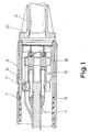
- the electronic switching device in the form of a proximity switch, shown schematically in section in FIG. 1, initially has an inner sleeve 1 closed on an end face (not shown in FIG. 1), a stopper 2 closing the inner sleeve 1 on the open end face, and an outer sleeve surrounding the inner sleeve 1 3 on.
- the inner sleeve 1 is made of electrically insulating plastic that is impermeable to water, dust and other media in the ambient atmosphere and is hermetically sealed and puncture-proof
- the plug 2 is designed as a cable bushing made of electrically insulating material that is suitable for water, dust and other media in the ambient atmosphere impermeable plastic and is hermetically sealed
- the outer sleeve 3 is made of metal.
- a conventional circuit arrangement 4 indicated here in the usual way on a circuit board, with a corresponding electrical connection device 5.
- part of the circuit arrangement 4 is an optical switching status indicator, preferably a light-emitting diode, which, for .
- the switching status indicator 6 is located directly on the inner wall of the inner sleeve 1 and can be seen from the outside of the outer sleeve 3, namely in the exemplary embodiment shown here and to that extent preferred through an observation opening 7 in the outer sleeve 3.
- the inner sleeve 1 is made in two parts, namely a first sleeve part 8 adjacent to the stopper 2, which is open on both sides and a second sleeve part 9 which is closed on one side, the first sleeve part 8 is made of transparent or translucent plastic and the second sleeve part 9 consists of plastic which is suitable in terms of connection technology, sealing technology and insulation technology and which is the same or equivalent, non-transparent or translucent, in particular colored.
- the first sleeve part 8 is designed as an extrusion part and the second sleeve part 9 as an injection molded part.
- the execution of the first sleeve part 8 as an extrusion part has the advantage that this first sleeve part 8 with practically any length at very ge ring wall thickness, for example with a wall thickness of approximately 0.4 mm.
- polysulfone or a similar plastic has proven to be particularly expedient as a material, in particular also taking into account the ultrasound plastic welding that is preferably to be used.
- Polysulfone is also known commercially as polyethersulfone, polyarylsulfone or polyphenylene sulfone.
- the above-mentioned selection of materials to be preferred for the inner sleeve 1 also applies in a similar way to the plug 2 of the electronic switching device according to the invention.
- the stopper 2 is also suitable for introducing the energy required for the ultrasonic plastic welding into the stopper 2 and into the inner sleeve 1.
- the stopper 2 which can be seen in FIG.
- FIG. 2 initially shows a large number of contexts moods with the embodiment shown in Fig. 1.
- the closed end of the inner sleeve 1 with the coil 11 of the proximity switch arranged behind it can be seen here; it is an inductive proximity switch.
- a circumferential annular bead 12 can also be seen on the inner sleeve 1, which, in conjunction with a corresponding annular groove 13 on the inside of the metallic outer sleeve 3, defines the relative position of the inner sleeve 1 and outer sleeve 3.
- the stopper 2 is constructed in the exemplary embodiment according to FIG. 2.
- the plug 2 is supported and sealed against the inner sleeve 1 by an O-ring 15 arranged on the outside in a receiving groove 14. So here the plug 2 is not permanently connected to the inner sleeve 1 by ultrasonic plastic welding, but by a press fit with the help of the O-ring 15.
- the plug 2 that the plug 2 has a central bushing 16 for a cable 17 and in the bushing 16 a circumferential contact flange 18 for an O-ring 19 surrounding the cable 17, on the plug 2 on the outside of the O-ring 19, an annular projection 20 is formed and when the cable 17 is inserted, the annular projection 20 is bent toward the cable 17 by permanent deformation, in particular at high temperature, of the plastic, and the O-ring 19 is thus pressed hermetically against the cable 17.
- the contact flange 18 is formed on a support ring 21 inserted in the stopper 2.
Landscapes
- Connector Housings Or Holding Contact Members (AREA)
- Switches That Are Operated By Magnetic Or Electric Fields (AREA)
- Casings For Electric Apparatus (AREA)
- Switch Cases, Indication, And Locking (AREA)
- Switches Operated By Changes In Physical Conditions (AREA)
- Electronic Switches (AREA)
Applications Claiming Priority (2)
| Application Number | Priority Date | Filing Date | Title |
|---|---|---|---|
| DE3818499A DE3818499A1 (de) | 1988-05-31 | 1988-05-31 | Elektronisches schaltgeraet, insbesondere naeherungsschalter |
| DE3818499 | 1988-05-31 |
Publications (3)
| Publication Number | Publication Date |
|---|---|
| EP0344569A2 true EP0344569A2 (fr) | 1989-12-06 |
| EP0344569A3 EP0344569A3 (fr) | 1991-07-17 |
| EP0344569B1 EP0344569B1 (fr) | 1995-08-02 |
Family
ID=6355517
Family Applications (1)
| Application Number | Title | Priority Date | Filing Date |
|---|---|---|---|
| EP89109202A Expired - Lifetime EP0344569B1 (fr) | 1988-05-31 | 1989-05-22 | Appareil de commutation électronique notament interrupteur de proximité |
Country Status (4)
| Country | Link |
|---|---|
| US (1) | US5018049A (fr) |
| EP (1) | EP0344569B1 (fr) |
| JP (1) | JPH0298026A (fr) |
| DE (2) | DE3818499A1 (fr) |
Families Citing this family (21)
| Publication number | Priority date | Publication date | Assignee | Title |
|---|---|---|---|---|
| CA2059427C (fr) * | 1991-01-22 | 2000-03-28 | Ichirou Ishibashi | Structure permettant d'empecher les pertes de courant dans les appareils de pulverisation electrostatique |
| DE4135876C2 (de) * | 1991-10-31 | 1994-03-10 | Ifm Electronic Gmbh | Elektronisches Schaltgerät |
| DE4225267C3 (de) * | 1992-03-19 | 2001-04-26 | Ifm Electronic Gmbh | Abdichtungsvorrichtung für ein elektronisches Schaltgerät |
| DE4244994B8 (de) * | 1992-03-19 | 2006-08-10 | I F M Electronic Gmbh | Gehäuse mit vergossenen Bauteilen |
| DE9208588U1 (de) * | 1992-06-29 | 1992-08-13 | I F M Electronic Gmbh, 45127 Essen | Elektrisches Schaltgerät |
| DE4345509C2 (de) * | 1992-09-30 | 2001-11-22 | Siemens Ag | Näherungsschalter |
| DE4341600C2 (de) * | 1993-12-07 | 1998-08-13 | Ifm Electronic Gmbh | Elektronisches Schaltgerät |
| US5712562A (en) | 1995-10-13 | 1998-01-27 | Bently Nevada Corporation | Encapsulated transducer with an alignment plug and method of manufacture |
| US5685884A (en) * | 1995-10-13 | 1997-11-11 | Bently Nevada Corporation | Method of making a transducer |
| US5818224A (en) * | 1995-10-13 | 1998-10-06 | Bently Nevada Corporation | Encapsulated transducer with an integrally formed full length sleeve and a component alignment preform and method of manufacture |
| US5770941A (en) * | 1995-10-13 | 1998-06-23 | Bently Nevada Corporation | Encapsulated transducer and method of manufacture |
| DE29721923U1 (de) * | 1997-12-11 | 1998-02-05 | Abb Patent Gmbh, 68309 Mannheim | Funkgerät |
| DE19923015A1 (de) * | 1999-05-20 | 2000-12-07 | Testo Gmbh & Co | Tragbares Bedien- und Anzeigegerät |
| DE10041166C2 (de) * | 2000-08-21 | 2002-11-14 | Ifm Electronic Gmbh | Elektronisches Schaltgerät |
| US6643909B2 (en) | 2001-04-10 | 2003-11-11 | Bently Nevada Llc | Method of making a proximity probe |
| DE10207762A1 (de) * | 2002-02-23 | 2003-09-04 | Endress & Hauser Gmbh & Co Kg | Elektrotechnisches Gerät |
| EP2018520A2 (fr) * | 2006-05-12 | 2009-01-28 | Baumer Electric AG | Boîtier de capteur |
| US8934217B2 (en) * | 2006-10-31 | 2015-01-13 | Linak A/S | Motor operator for switchgear for mains power distribution systems |
| CN107464675A (zh) * | 2017-09-26 | 2017-12-12 | 绵阳鑫阳知识产权运营有限公司 | 一种强化型变压器引线套管 |
| DE102021101181B4 (de) | 2021-01-21 | 2022-09-08 | Sick Ag | Gehäuse für einen induktiven Sensor und ein Verfahren zur Herstellung eines Gehäuses füreinen induktiven Sensor |
| DE102024102780A1 (de) * | 2024-01-31 | 2025-07-31 | Ifm Electronic Gmbh | Elektronisches Gerät der Automatisierungstechnik mit einer zweifach mit Kunstoff umpritzten Elektronikplatine sowie ein Herstellungsverfahren |
Family Cites Families (8)
| Publication number | Priority date | Publication date | Assignee | Title |
|---|---|---|---|---|
| JPS567243B2 (fr) * | 1973-05-14 | 1981-02-17 | ||
| DE2724939C3 (de) * | 1977-06-02 | 1984-08-09 | Buck, Robert, Ing.(grad.), 7995 Neukirch | Schaltgerät, insbesondere elektronisches, berührungslos arbeitendes Schaltgerät |
| DE2951968C2 (de) * | 1979-12-22 | 1984-03-29 | Eduard 7303 Neuhausen Hermle | Elektrischer Näherungsschalter |
| DE3029595C1 (de) * | 1980-08-05 | 1981-10-01 | Ifm Electronic Gmbh, 4300 Essen | Schaltzustandsanzeige fuer ein elektrisches,insbesondere elektronisches,beruehrungslos arbeitendes Schaltgeraet |
| DE3117386C1 (de) * | 1981-05-02 | 1982-10-28 | Gebhard Balluff, Fabrik Feinmechanischer Erzeugnisse, 7303 Neuhausen | Näherungsschalter |
| DE3203944A1 (de) * | 1982-02-05 | 1983-08-11 | Willi 7031 Nufringen Hanesch | Gehaeuse fuer einen naeherungsschalter und verfahren zu dessen herstellung |
| DE3215632C2 (de) * | 1982-04-27 | 1991-05-29 | R. Stahl Schaltgeräte GmbH, 7118 Künzelsau | Gehäuseverschluß für explosionsgeschützte Gehäuse |
| US4785240A (en) * | 1984-10-01 | 1988-11-15 | Square D Company | Proximity switch |
-
1988
- 1988-05-31 DE DE3818499A patent/DE3818499A1/de active Granted
-
1989
- 1989-05-22 EP EP89109202A patent/EP0344569B1/fr not_active Expired - Lifetime
- 1989-05-22 DE DE58909368T patent/DE58909368D1/de not_active Expired - Fee Related
- 1989-05-22 US US07/355,019 patent/US5018049A/en not_active Expired - Lifetime
- 1989-05-29 JP JP1132925A patent/JPH0298026A/ja active Pending
Also Published As
| Publication number | Publication date |
|---|---|
| DE3818499C2 (fr) | 1991-07-25 |
| EP0344569A3 (fr) | 1991-07-17 |
| JPH0298026A (ja) | 1990-04-10 |
| EP0344569B1 (fr) | 1995-08-02 |
| DE58909368D1 (de) | 1995-09-07 |
| US5018049A (en) | 1991-05-21 |
| DE3818499A1 (de) | 1989-12-07 |
Similar Documents
| Publication | Publication Date | Title |
|---|---|---|
| EP0344569B1 (fr) | Appareil de commutation électronique notament interrupteur de proximité | |
| DE2724939C3 (de) | Schaltgerät, insbesondere elektronisches, berührungslos arbeitendes Schaltgerät | |
| DE19528678C1 (de) | Einbaustecker | |
| DE3123594C2 (fr) | ||
| EP0122465A2 (fr) | Commutateur électrique ou bouton poussoir contenant deux bascules à grande surface | |
| EP1284333A2 (fr) | Ensemble composant électrique | |
| DE2713213B1 (de) | Schaltgeraet,insbesondere elektronisches,beruehrungslos arbeitendes Schaltgeraet | |
| EP0346587A2 (fr) | Traversée de câble | |
| DE3325462C2 (de) | Elektrisches, insbesondere elektronisches, berührungslos arbeitendes Schaltgerät | |
| DE102020111359A1 (de) | Berührgeschützte Verbindungsanordnung von zwei elektrischen Leitern sowie Kraftfahrzeug mit einer solchen Verbindungsanordnung | |
| DE19625589B4 (de) | Näherungsschalter | |
| EP4135168A1 (fr) | Dispositif interface électrique pour un moteur électrique | |
| DE10008885A1 (de) | Kupplung oder Stecker für eine Steckverbindung zur Anwendung in der Messtechnik, insbesondere in der Umweltmesstechnik | |
| DE19543372C5 (de) | Winkelmeßeinrichtung | |
| DE3024510C2 (de) | Staubdichter elektrischer Schalter | |
| DE2742647A1 (de) | Spannungspruefergehaeuse | |
| DE102013225100A1 (de) | Induktiver Näherungsschalter mit einem Ferritkern | |
| EP0989567A1 (fr) | Dispositif encapsulé en résine | |
| DE102010046752A1 (de) | Schaltelement | |
| DE2622482C2 (de) | Annäherungsschalter | |
| DE10131218C1 (de) | Hinterleuchteter Tastschalter | |
| DE19539840B4 (de) | Anzeigeanordnung | |
| EP2697542B1 (fr) | Dispositif de commande et de signalisation | |
| DE19920403B4 (de) | Optoelektronischer Koppler | |
| DE1490385A1 (de) | Kabelstecker fuer koaxiale Hochfrequenzkabel |
Legal Events
| Date | Code | Title | Description |
|---|---|---|---|
| PUAI | Public reference made under article 153(3) epc to a published international application that has entered the european phase |
Free format text: ORIGINAL CODE: 0009012 |
|
| AK | Designated contracting states |
Kind code of ref document: A2 Designated state(s): CH DE FR GB LI SE |
|
| 17P | Request for examination filed |
Effective date: 19891228 |
|
| PUAL | Search report despatched |
Free format text: ORIGINAL CODE: 0009013 |
|
| AK | Designated contracting states |
Kind code of ref document: A3 Designated state(s): CH DE FR GB LI SE |
|
| 17Q | First examination report despatched |
Effective date: 19931124 |
|
| GRAA | (expected) grant |
Free format text: ORIGINAL CODE: 0009210 |
|
| AK | Designated contracting states |
Kind code of ref document: B1 Designated state(s): CH DE FR GB LI SE |
|
| REF | Corresponds to: |
Ref document number: 58909368 Country of ref document: DE Date of ref document: 19950907 |
|
| GBT | Gb: translation of ep patent filed (gb section 77(6)(a)/1977) |
Effective date: 19950814 |
|
| ET | Fr: translation filed | ||
| PG25 | Lapsed in a contracting state [announced via postgrant information from national office to epo] |
Ref country code: SE Effective date: 19951102 |
|
| PG25 | Lapsed in a contracting state [announced via postgrant information from national office to epo] |
Ref country code: LI Effective date: 19960531 Ref country code: CH Effective date: 19960531 |
|
| PLBE | No opposition filed within time limit |
Free format text: ORIGINAL CODE: 0009261 |
|
| STAA | Information on the status of an ep patent application or granted ep patent |
Free format text: STATUS: NO OPPOSITION FILED WITHIN TIME LIMIT |
|
| 26N | No opposition filed | ||
| REG | Reference to a national code |
Ref country code: CH Ref legal event code: PL |
|
| REG | Reference to a national code |
Ref country code: GB Ref legal event code: IF02 |
|
| PGFP | Annual fee paid to national office [announced via postgrant information from national office to epo] |
Ref country code: DE Payment date: 20020402 Year of fee payment: 14 |
|
| REG | Reference to a national code |
Ref country code: FR Ref legal event code: RN |
|
| REG | Reference to a national code |
Ref country code: FR Ref legal event code: D3 |
|
| PG25 | Lapsed in a contracting state [announced via postgrant information from national office to epo] |
Ref country code: DE Free format text: LAPSE BECAUSE OF NON-PAYMENT OF DUE FEES Effective date: 20031202 |
|
| PG25 | Lapsed in a contracting state [announced via postgrant information from national office to epo] |
Ref country code: FR Free format text: LAPSE BECAUSE OF NON-PAYMENT OF DUE FEES Effective date: 20031231 |
|
| REG | Reference to a national code |
Ref country code: FR Ref legal event code: ST |
|
| REG | Reference to a national code |
Ref country code: FR Ref legal event code: RN |
|
| REG | Reference to a national code |
Ref country code: FR Ref legal event code: RN Ref country code: FR Ref legal event code: D3 |
|
| PGFP | Annual fee paid to national office [announced via postgrant information from national office to epo] |
Ref country code: GB Payment date: 20050513 Year of fee payment: 17 |
|
| PGFP | Annual fee paid to national office [announced via postgrant information from national office to epo] |
Ref country code: FR Payment date: 20051019 Year of fee payment: 17 |
|
| PG25 | Lapsed in a contracting state [announced via postgrant information from national office to epo] |
Ref country code: GB Free format text: LAPSE BECAUSE OF NON-PAYMENT OF DUE FEES Effective date: 20060522 |
|
| GBPC | Gb: european patent ceased through non-payment of renewal fee |
Effective date: 20060522 |
|
| REG | Reference to a national code |
Ref country code: FR Ref legal event code: ST Effective date: 20070131 |