EP0344569A2 - Elektronisches Schaltgerät, insbesondere Näherungsschalter - Google Patents
Elektronisches Schaltgerät, insbesondere Näherungsschalter Download PDFInfo
- Publication number
- EP0344569A2 EP0344569A2 EP89109202A EP89109202A EP0344569A2 EP 0344569 A2 EP0344569 A2 EP 0344569A2 EP 89109202 A EP89109202 A EP 89109202A EP 89109202 A EP89109202 A EP 89109202A EP 0344569 A2 EP0344569 A2 EP 0344569A2
- Authority
- EP
- European Patent Office
- Prior art keywords
- sleeve
- switching device
- electronic switching
- sleeve part
- plug
- Prior art date
- Legal status (The legal status is an assumption and is not a legal conclusion. Google has not performed a legal analysis and makes no representation as to the accuracy of the status listed.)
- Granted
Links
- 239000004033 plastic Substances 0.000 claims abstract description 17
- 229920003023 plastic Polymers 0.000 claims abstract description 17
- 239000000428 dust Substances 0.000 claims abstract description 7
- XLYOFNOQVPJJNP-UHFFFAOYSA-N water Substances O XLYOFNOQVPJJNP-UHFFFAOYSA-N 0.000 claims abstract description 7
- 238000001125 extrusion Methods 0.000 claims abstract description 5
- 238000005516 engineering process Methods 0.000 claims description 15
- 238000004023 plastic welding Methods 0.000 claims description 8
- 238000009413 insulation Methods 0.000 claims description 6
- 238000007789 sealing Methods 0.000 claims description 6
- 239000002184 metal Substances 0.000 claims description 5
- 230000003287 optical effect Effects 0.000 claims description 5
- 229920002492 poly(sulfone) Polymers 0.000 claims description 4
- 238000002347 injection Methods 0.000 description 3
- 239000007924 injection Substances 0.000 description 3
- 239000000463 material Substances 0.000 description 3
- 238000013459 approach Methods 0.000 description 2
- 230000001939 inductive effect Effects 0.000 description 2
- 239000004695 Polyether sulfone Substances 0.000 description 1
- 239000011324 bead Substances 0.000 description 1
- 239000002131 composite material Substances 0.000 description 1
- 239000012777 electrically insulating material Substances 0.000 description 1
- 238000000034 method Methods 0.000 description 1
- 230000036651 mood Effects 0.000 description 1
- 230000005693 optoelectronics Effects 0.000 description 1
- 229920006393 polyether sulfone Polymers 0.000 description 1
- 229920012287 polyphenylene sulfone Polymers 0.000 description 1
- 239000011347 resin Substances 0.000 description 1
- 229920005989 resin Polymers 0.000 description 1
- 238000002604 ultrasonography Methods 0.000 description 1
Images

Classifications
-
- H—ELECTRICITY
- H03—ELECTRONIC CIRCUITRY
- H03K—PULSE TECHNIQUE
- H03K17/00—Electronic switching or gating, i.e. not by contact-making and –breaking
- H03K17/94—Electronic switching or gating, i.e. not by contact-making and –breaking characterised by the way in which the control signals are generated
- H03K17/945—Proximity switches
-
- H—ELECTRICITY
- H01—ELECTRIC ELEMENTS
- H01H—ELECTRIC SWITCHES; RELAYS; SELECTORS; EMERGENCY PROTECTIVE DEVICES
- H01H9/00—Details of switching devices, not covered by groups H01H1/00 - H01H7/00
- H01H9/02—Bases, casings, or covers
- H01H9/04—Dustproof, splashproof, drip-proof, waterproof, or flameproof casings
-
- H—ELECTRICITY
- H01—ELECTRIC ELEMENTS
- H01H—ELECTRIC SWITCHES; RELAYS; SELECTORS; EMERGENCY PROTECTIVE DEVICES
- H01H9/00—Details of switching devices, not covered by groups H01H1/00 - H01H7/00
- H01H9/16—Indicators for switching condition, e.g. "on" or "off"
- H01H9/161—Indicators for switching condition, e.g. "on" or "off" comprising light emitting elements
Definitions
- the invention relates to an electronic switching device with an inner sleeve closed on one end face, a plug closing the inner sleeve on the open end face and an outer sleeve surrounding the inner sleeve, the inner sleeve being made of electrically insulating plastic that is impervious to water, dust and other media in the ambient atmosphere consists of hermetically sealed and puncture-proof, the plug is designed as a cable entry, made of electrically insulating plastic that is impermeable to water, dust and other media in the surrounding atmosphere, and is hermetically sealed and the outer sleeve is made of metal.
- Electronic switching devices of the type explained above are known in a large number of embodiments, in particular as inductive, capacitive and optoelectronic proximity switches.
- the outer sleeve which is made of metal and is provided with an external thread, such switching devices can be screwed into dimensionally specified threaded sockets at the place of use.
- the clear diameter available for the circuit arrangement is determined by the fixed predetermined outer diameter and by the wall thicknesses of the inner sleeve and the outer sleeve.
- very small wall thicknesses namely wall thicknesses of less than 0.5 mm, preferably of approximately 0.4 mm, have to be realized for the inner sleeve.
- the electronic switching device known from practice with a one-piece, namely injection molded inner sleeve has a maximum length of approximately 40 mm for wall thicknesses of the relevant size here for reasons of injection technology. This is not enough for many applications. Otherwise, the special problem explained above remains in connection with an optical switching state indicator, in particular a light-emitting diode.
- the invention is based on the object of improving the known electronic switching device in such a way that, even with the required small wall thickness of the inner sleeve, it meets high requirements for tightness and dielectric strength, for example for the VDE protection class IP 67.
- the electronic switching device in which the above-mentioned object is achieved, is characterized in that the inner sleeve is made in two parts, namely from a first sleeve part adjacent to the plug, which is open on both sides and a second sleeve part which is closed on one side, the first sleeve part transparent or translucent plastic and the second sleeve part consists of the same in terms of connection technology to the first sleeve part, sealing technology and insulation technology the same or equivalent, non-transparent or translucent, in particular colored plastic and the first sleeve part and the second sleeve part are permanently hermetically sealed and puncture-proof.
- the inner sleeve like the outer sleeve made of metal, can be produced in practically any length, even with the required small wall thicknesses.
- the first sleeve part as an extrusion part and the second sleeve can be designed as a molded part.
- Polysulfone can preferably be used as the material for the first sleeve part and / or the second sleeve part and / or the plug.
- the first sleeve part and the second sleeve part are connected to one another by ultrasonic plastic welding.
- the ultrasonic plastic welding leads to such a perfect, permanent bond between the two sleeve parts that they act as a continuous inner sleeve in terms of sealing technology and insulation technology, i.e. there is no weak point in sealing technology or insulation technology at the connection point of the two sleeve parts.
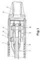
- the electronic switching device in the form of a proximity switch, shown schematically in section in FIG. 1, initially has an inner sleeve 1 closed on an end face (not shown in FIG. 1), a stopper 2 closing the inner sleeve 1 on the open end face, and an outer sleeve surrounding the inner sleeve 1 3 on.
- the inner sleeve 1 is made of electrically insulating plastic that is impermeable to water, dust and other media in the ambient atmosphere and is hermetically sealed and puncture-proof
- the plug 2 is designed as a cable bushing made of electrically insulating material that is suitable for water, dust and other media in the ambient atmosphere impermeable plastic and is hermetically sealed
- the outer sleeve 3 is made of metal.
- a conventional circuit arrangement 4 indicated here in the usual way on a circuit board, with a corresponding electrical connection device 5.
- part of the circuit arrangement 4 is an optical switching status indicator, preferably a light-emitting diode, which, for .
- the switching status indicator 6 is located directly on the inner wall of the inner sleeve 1 and can be seen from the outside of the outer sleeve 3, namely in the exemplary embodiment shown here and to that extent preferred through an observation opening 7 in the outer sleeve 3.
- the inner sleeve 1 is made in two parts, namely a first sleeve part 8 adjacent to the stopper 2, which is open on both sides and a second sleeve part 9 which is closed on one side, the first sleeve part 8 is made of transparent or translucent plastic and the second sleeve part 9 consists of plastic which is suitable in terms of connection technology, sealing technology and insulation technology and which is the same or equivalent, non-transparent or translucent, in particular colored.
- the first sleeve part 8 is designed as an extrusion part and the second sleeve part 9 as an injection molded part.
- the execution of the first sleeve part 8 as an extrusion part has the advantage that this first sleeve part 8 with practically any length at very ge ring wall thickness, for example with a wall thickness of approximately 0.4 mm.
- polysulfone or a similar plastic has proven to be particularly expedient as a material, in particular also taking into account the ultrasound plastic welding that is preferably to be used.
- Polysulfone is also known commercially as polyethersulfone, polyarylsulfone or polyphenylene sulfone.
- the above-mentioned selection of materials to be preferred for the inner sleeve 1 also applies in a similar way to the plug 2 of the electronic switching device according to the invention.
- the stopper 2 is also suitable for introducing the energy required for the ultrasonic plastic welding into the stopper 2 and into the inner sleeve 1.
- the stopper 2 which can be seen in FIG.
- FIG. 2 initially shows a large number of contexts moods with the embodiment shown in Fig. 1.
- the closed end of the inner sleeve 1 with the coil 11 of the proximity switch arranged behind it can be seen here; it is an inductive proximity switch.
- a circumferential annular bead 12 can also be seen on the inner sleeve 1, which, in conjunction with a corresponding annular groove 13 on the inside of the metallic outer sleeve 3, defines the relative position of the inner sleeve 1 and outer sleeve 3.
- the stopper 2 is constructed in the exemplary embodiment according to FIG. 2.
- the plug 2 is supported and sealed against the inner sleeve 1 by an O-ring 15 arranged on the outside in a receiving groove 14. So here the plug 2 is not permanently connected to the inner sleeve 1 by ultrasonic plastic welding, but by a press fit with the help of the O-ring 15.
- the plug 2 that the plug 2 has a central bushing 16 for a cable 17 and in the bushing 16 a circumferential contact flange 18 for an O-ring 19 surrounding the cable 17, on the plug 2 on the outside of the O-ring 19, an annular projection 20 is formed and when the cable 17 is inserted, the annular projection 20 is bent toward the cable 17 by permanent deformation, in particular at high temperature, of the plastic, and the O-ring 19 is thus pressed hermetically against the cable 17.
- the contact flange 18 is formed on a support ring 21 inserted in the stopper 2.
Landscapes
- Connector Housings Or Holding Contact Members (AREA)
- Switches That Are Operated By Magnetic Or Electric Fields (AREA)
- Casings For Electric Apparatus (AREA)
- Switch Cases, Indication, And Locking (AREA)
- Switches Operated By Changes In Physical Conditions (AREA)
- Electronic Switches (AREA)
Abstract
Description
- Die Erfindung betrifft ein elektronisches Schaltgerät, mit einer an einer Stirnseite geschlossenen Innenhülse, einem die Innenhülse an der offenen Stirnseite verschließenden Stopfen und einer die Innenhülse umgebenden Außenhülse, wobei die Innenhülse aus elektrisch isolierendem, für Wasser, Staub und andere Medien in der Umgebungsatmosphäre undurchlässigen Kunststoff besteht sowie hermetisch dicht und durchschlagsfest ausgeführt ist, der Stopfen als Kabeldurchführung ausgebildet ist, aus elektrisch isolierendem, für Wasser, Staub und andere Medien in der Umgebungsatmosphäre undurchlässigen Kunststoff besteht und hermetisch dicht ausgeführt ist und die Außenhülse aus Metall besteht.
- Elektronische Schaltgeräte der zuvor erläuterten Art sind in einer Vielzahl von Ausführungsformen bekannt, insbesondere als induktive, kapazitive und optoelektronische Näherungsschalter. Mit Hilfe der aus Metall bestehenden und mit einem Außengewinde versehenen Außenhülse können solche Schaltgeräte in maßlich vorgegebene Gewindefassungen am Einsatzort eingeschraubt werden. Der für die Schaltungsanordnung zur Verfügung stehende lichte Durchmesser wird durch den fest vorgegebenen Außendurchmesser und durch die Wandstärken der Innenhülse und der Außenhülse bestimmt. Bei einem kleinen Außendurchmesser, nämlich 18 mm und weniger, muß man für die Innenhülse sehr geringe Wandstärken, nämlich Wandstärken von weniger als 0,5 mm, vorzugsweise von ca. 0,4 mm realisieren. Das wiederum kollidiert mit höheren Anforderungen an die Dichtigkeit und Durchschlagsfestigkeit, wie sie beispielsweise für die VDE-Schutzart IP 67 gestellt sind. Diese Anforderungen erfordern nach derzeitiger Meinung der Fachwelt regelmäßig den Verguß der Schaltungsanordnung mit Gießharz.
- Ein besonderes Problem ergibt sich dann, wenn im Inneren der Innenhülse ein optischer Schaltzustandsanzeiger vorgesehen ist, der von außerhalb der Außenhülse erkennbar sein soll. Eine Vielzahl von Ansätzen sind bislang gemacht worden, um unter diesen Voraussetzungen die z. B. für die VDE-Schutzart IP 67 gestellten Anforderungen an Dichtigkeit und Durchschlagsfestigkeit zu erreichen (vgl. die DE-PS 30 29 595 einschließlich des dort referierten Standes der Technik). Soweit diese bekannten Lösungsansätze grundsätzlich sinnvoll sind, sind sie jedenfalls bei den vorliegend geforderten geringen Wandstärken nicht realisierbar.
- Das aus der Praxis bekannte elektronische Schaltgerät mit einstückig ausgeführter, nämlich gespritzter Innenhülse hat bei Wandstärken in der hier relevanten Größenordnung aus spritztechnischen Gründen eine maximale Länge von ca. 40 mm. Dies reicht für viele Anwendungsfälle nicht aus. Im übrigen verbleibt das zuvor erläuterte Sonderproblem in Verbindung mit einem optischen Schaltzustandsanzeiger, insbesondere einer Leuchtdiode.
- Der Erfindung liegt nun die Aufgabe zugrunde, das bekannte elektronische Schaltgerät so zu verbessern, daß es auch bei der geforderten geringen Wandstärke der Innenhülse hohe Anforderungen an Dichtigkeit und Durchschlagsfestigkeit erfüllt, beispielsweise für die VDE-Schutzart IP 67.
- Das erfindungsgemäße elektronische Schaltgerät, bei dem die zuvor aufgezeigte Aufgabe gelöst ist, ist dadurch gekennzeichnet, daß die Innenhülse zweiteilig ausgeführt ist, nämlich aus einem ersten, dem Stopfen benachbarten, beidseitig offenen Hülsenteil und einem zweiten, einseitig geschlossenen Hülsenteil besteht, das erste Hülsenteil aus durchsichtigem oder durchscheinendem Kunststoff und das zweite Hülsenteil aus zu dem ersten Hülsenteil verbindungstechnisch passendem, abdichtungstechnisch und isolationstechnisch gleichen oder gleichwertigen, nicht durchsichtigen oder durchscheinenden, insbesondere eingefärbten Kunststoff besteht und das erste Hülsenteil und das zweite Hülsenteil miteinander dauerhaft hermetisch dicht und durchschlagsfest verbunden sind. Dadurch läßt sich die Innenhülse, wie auch die Außenhülse aus Metall, in praktisch jeder beliebigen Länge auch bei den geforderten geringen Wandstärken herstellen. Insbesondere kann das erste Hülsenteil als Extrusionsteil und das zweite Hül senteil als Spritzteil ausgeführt werden. Für das erste Hülsenteil und/oder das zweite Hülsenteil und/oder den Stopfen kann als Werkstoff vorzugsweise Polysulfon verwendet werden.
- Bei einer besonders bevorzugten Ausführungsform des erfindungsgemäßen Schaltgerätes sind das erste Hülsenteil und das zweite Hülsenteil durch Ultraschall-Kunststoffschweißung miteinander verbunden. Entsprechende Kunststoffe vorausgesetzt, führt die Ultraschall-Kunststoffschweißung zu einem derart perfekten, dauerhaften Verbund der beiden Hülsenteile, daß diese abdichtungstechnisch und isolationstechnisch wie eine durchgehende Innenhülse wirken, also an der Verbindungsstelle der beiden Hülsenteile keine Schwachstelle in abdichtungstechnischer oder in isolationstechnischer Hinsicht entsteht.
- Es gibt nun noch eine Vielzahl von Möglichkeiten, die Lehre der Erfindung auszugestalten und weiterzubilden. Dazu darf zunächst auf die dem Patentanspruch 1 nachgeordneten Patentansprüche verwiesen werden. Im übrigen wird verwiesen auf die nachfolgende, anhand der Zeichnung gegebenen Erläuterung von zwei bevorzugten Ausführungsbeispielen erfindungsgemäßer elektronischer Schaltgeräte. In der Zeichnung zeigt
- Fig. 1 im Schnitt ein erstes Ausführungsbeispiel eines erfindungsgemäßen elektronischen Schaltgerätes und
- Fig. 2 ebenfalls im Schnitt ein zweites Ausführungsbeispiel eines erfindungsgemäßen elektronischen Schaltgerätes.
- Das in Fig. 1 im Schnitt schematisch dargestellte elektronische Schaltgerät in Form eines Näherungsschalters weist zunächst eine an einer, in Fig. 1 nicht dargestellten Stirnseite geschlossene Innenhülse 1, einen die Innenhülse 1 an der offenen Stirnseite verschließenden Stopfen 2 und eine die Innenhülse 1 umgebende Außenhülse 3 auf. Dabei gilt im einzelnen, daß die Innenhülse 1 aus elektrisch isolierendem, für Wasser, Staub und andere Medien in der Umgebungsatmosphäre undurchlässigen Kunststoff besteht sowie hermetisch dicht und durchschlagsfest ausgeführt ist, der Stopfen 2 als Kabeldurchführung ausgebildet ist, aus elektrisch isolierendem, für Wasser, Staub und andere Medien in der Umgebungsatmosphäre undurchlässigen Kunststoff besteht und hermetisch dicht ausgeführt ist und die Außenhülse 3 aus Metall besteht. Im Inneren der Innenhülse 1 befindet sich eine übliche Schaltungsanordnung 4, hier in üblicher Weise auf einer Schaltungsplatine angedeutet, mit einer entsprechenden elektrischen Anschlußeinrichtung 5. Im hier dargestellten und insoweit bevorzugten Ausführungsbeispiel ist Teil der Schaltungsanordnung 4 ein optischer Schaltzustandsanzeiger, vorzugsweise eine Leuchtdiode, die z. B. dann Licht emittiert, wenn das Schaltgerät durchgeschaltet hat, oder die Farbe wechselt, wenn sich der Schaltzustand des Schaltgerätes ändert. Der Schaltzustandsanzeiger 6 befindet sich unmittelbar an der Innenwandung der Innenhülse 1 und ist von außerhalb der Außenhülse 3 erkennbar, nämlich im hier dargestellten und insoweit bevorzugten Ausführungsbeispiel durch eine Beobachtungsöffnung 7 in der Außenhülse 3.
- Wesentlich ist nun, daß die Innenhülse 1 zweiteilig ausgeführt ist, nämlich aus einem ersten, dem Stopfen 2 benachbarten, beidseitig offenen Hülsenteil 8 und einem zweiten, einseitig geschlossenen Hülsenteil 9 besteht, das erste Hülsenteil 8 aus durchsichtigem oder durchscheinendem Kunststoff und das zweite Hülsenteil 9 aus zu dem ersten Hülsenteil 8 verbindungstechnisch passendem, abdichtungstechnisch und isolationstechnisch gleichen oder gleichwertigen, nicht durchsichtigen oder durchscheinenden, insbesondere eingefärbten Kunststoff besteht.
- In den dargestellten Ausführungsbeispielen ist das erste Hülsenteil 8 als Extrusionsteil und das zweite Hülsenteil 9 als Spritzteil ausgeführt. Die Ausführung des ersten Hülsenteils 8 als Extrusionsteil hat den Vorteil, daß dieses erste Hülsenteil 8 mit praktisch beliebiger Länge bei sehr ge ringer Wandstärke, beispielsweise bei einer Wandstärke von ca. 0,4 mm hergestellt werden kann.
- Von besonderer Bedeutung ist eine Lehre der Erfindung, die in der Zeichnung nur andeutungsweise zu erkennen ist. Diese Lehre geht nämlich dahin, das erste Hülsenteil 8 und das zweite Hülsenteil 9 durch Ultraschall-Kunststoffschweißung miteinander zu verbinden. Diese Verbindungstechnik ist deshalb für den vorliegenden Anwendungsfall besonders geeignet, weil sich ein inniger Stoffverbund der beiden Hülsenteile 8 und 9 ergibt, der die zunächst eigenständigen Hülsenteile 8 und 9 der Innenhülse 1 abdichtungstechnisch und isolationstechnisch wie eine einteilige Innenhülse 1 erscheinen läßt. Dadurch läßt sich die VDE-Schutzart IP 67 mit einer Durchschlagsfestigkeit von 5 kV trotz der geforderten geringen Wandstärke der Innenhülse 1 realisieren, ohne daß die Schaltungsanordnung 4 im Inneren der Innenhülse 1 vergossen werden müßte.
- Für die Innenhülse 1 hat sich als Werkstoff Polysulfon oder ein ähnlicher Kunststoff als besonders zweckmäßig erwiesen, insbesondere auch unter Berücksichtigung der vorzugsweise anzuwendenden Ultraschall-Kunststoffschweissung. Polysulfon ist im Handel auch unter den Namen Polyethersulfon, Polyarylsulfon oder Polyphenylensulfon bekannt.
- Die zuvor erläuterte, für die Innenhülse 1 zu bevorzugende Werkstoffauswahl gilt in ähnlicher Weise auch für den Stopfen 2 des erfindungsgemäßen elektronischen Schaltgerätes. Der Stopfen 2 eignet sich im übrigen auch zur Einleitung der für die Ultraschall-Kunststoffschweißung erforderlichen Energie in den Stopfen 2 und in die Innenhülse 1. Dazu weist der in Fig. 1 erkennbare Stopfen 2 außen Anlageflächen 10 für eine nicht dargestellte Ultraschall-Schwingungseinrichtung auf.
- Das in Fig. 2 dargestellte, weiter bevorzugte Ausführungsbeispiel eines erfindungsgemäßen Schaltgerätes zeigt zunächst eine Vielzahl von Überein stimmungen mit dem in Fig. 1 dargestellten Ausführungsbeispiel. Erkennbar ist hier jedoch das geschlossene Ende der Innenhülse 1 mit dahinter angeordneter Spule 11 des Näherungsschalters; es handelt sich hier also um einen induktiven Näherungsschalter. Erkennbar ist an der Innenhülse 1 auch eine umlaufende Ringsicke 12, die in Verbindung mit einer entsprechenden Ringnut 13 auf der Innenseite der metallischen Außenhülse 3 die Relativlage von Innenhülse 1 und Außenhülse 3 definiert.
- Abweichend vom Ausführungsbeispiel nach Fig. 1 ist bei dem Ausführungsbeispiel nach Fig. 2 der Stopfen 2 konstruiert. Hier gilt zunächst, daß der Stopfen 2 über einen auf der Außenseite in einer Aufnahmenut 14 angeordneten O-Ring 15 gegenüber der Innenhülse 1 abgestützt und abgedichtet ist. Hier besteht also die Verbindung des Stopfens 2 zur Innenhülse 1 nicht dauerhaft durch Ultraschall-Kunststoffschweißung, sondern durch einen Preßsitz mit Hilfe des O-Ringes 15.
- Im übrigen gilt für das Ausführungsbeispiel nach Fig. 2, daß der Stopfen 2 eine mittige Durchführung 16 für ein Kabel 17 und in der Durchführung 16 einen umlaufenden Anlageflansch 18 für einen das Kabel 17 umgebenden O-Ring 19 aufweist, am Stopfen 2 auf der Außenseite des O-Rings 19 ein Ringvorsprung 20 ausgebildet ist und bei eingestecktem Kabel 17 der Ringvorsprung 20 durch bleibende, insbesondere unter hoher Temperatur ablaufende Verformung des Kunststoffs an das Kabel 17 herangebogen und dadurch der O-Ring 19 hermetisch abdichtend an das Kabel 17 herangedrückt ist. Dabei ist im übrigen der Anlageflansch 18 an einem in dem Stopfen 2 eingesetzten Stützring 21 ausgebildet.
Claims (10)
Applications Claiming Priority (2)
| Application Number | Priority Date | Filing Date | Title |
|---|---|---|---|
| DE3818499 | 1988-05-31 | ||
| DE3818499A DE3818499A1 (de) | 1988-05-31 | 1988-05-31 | Elektronisches schaltgeraet, insbesondere naeherungsschalter |
Publications (3)
| Publication Number | Publication Date |
|---|---|
| EP0344569A2 true EP0344569A2 (de) | 1989-12-06 |
| EP0344569A3 EP0344569A3 (de) | 1991-07-17 |
| EP0344569B1 EP0344569B1 (de) | 1995-08-02 |
Family
ID=6355517
Family Applications (1)
| Application Number | Title | Priority Date | Filing Date |
|---|---|---|---|
| EP89109202A Expired - Lifetime EP0344569B1 (de) | 1988-05-31 | 1989-05-22 | Elektronisches Schaltgerät, insbesondere Näherungsschalter |
Country Status (4)
| Country | Link |
|---|---|
| US (1) | US5018049A (de) |
| EP (1) | EP0344569B1 (de) |
| JP (1) | JPH0298026A (de) |
| DE (2) | DE3818499A1 (de) |
Families Citing this family (21)
| Publication number | Priority date | Publication date | Assignee | Title |
|---|---|---|---|---|
| CA2059427C (en) * | 1991-01-22 | 2000-03-28 | Ichirou Ishibashi | Structure for preventing current from leaking out of devices for electrostatic spray coating |
| DE4135876C2 (de) * | 1991-10-31 | 1994-03-10 | Ifm Electronic Gmbh | Elektronisches Schaltgerät |
| DE4244994B8 (de) * | 1992-03-19 | 2006-08-10 | I F M Electronic Gmbh | Gehäuse mit vergossenen Bauteilen |
| DE4225267C3 (de) * | 1992-03-19 | 2001-04-26 | Ifm Electronic Gmbh | Abdichtungsvorrichtung für ein elektronisches Schaltgerät |
| DE9208588U1 (de) * | 1992-06-29 | 1992-08-13 | I F M Electronic Gmbh, 45127 Essen | Elektrisches Schaltgerät |
| DE4345509C2 (de) * | 1992-09-30 | 2001-11-22 | Siemens Ag | Näherungsschalter |
| DE4341600C2 (de) * | 1993-12-07 | 1998-08-13 | Ifm Electronic Gmbh | Elektronisches Schaltgerät |
| US5770941A (en) * | 1995-10-13 | 1998-06-23 | Bently Nevada Corporation | Encapsulated transducer and method of manufacture |
| US5818224A (en) * | 1995-10-13 | 1998-10-06 | Bently Nevada Corporation | Encapsulated transducer with an integrally formed full length sleeve and a component alignment preform and method of manufacture |
| US5712562A (en) * | 1995-10-13 | 1998-01-27 | Bently Nevada Corporation | Encapsulated transducer with an alignment plug and method of manufacture |
| US5685884A (en) * | 1995-10-13 | 1997-11-11 | Bently Nevada Corporation | Method of making a transducer |
| DE29721923U1 (de) * | 1997-12-11 | 1998-02-05 | Abb Patent Gmbh, 68309 Mannheim | Funkgerät |
| DE19923015A1 (de) * | 1999-05-20 | 2000-12-07 | Testo Gmbh & Co | Tragbares Bedien- und Anzeigegerät |
| DE10041166C2 (de) * | 2000-08-21 | 2002-11-14 | Ifm Electronic Gmbh | Elektronisches Schaltgerät |
| US6643909B2 (en) | 2001-04-10 | 2003-11-11 | Bently Nevada Llc | Method of making a proximity probe |
| DE10207762A1 (de) | 2002-02-23 | 2003-09-04 | Endress & Hauser Gmbh & Co Kg | Elektrotechnisches Gerät |
| EP2018520A2 (de) * | 2006-05-12 | 2009-01-28 | Baumer Electric AG | Sensorgehäuse |
| ATE531059T1 (de) * | 2006-10-31 | 2011-11-15 | Linak As | Motorbetätigungsglied für eine schaltanlage für stromnetzsysteme |
| CN107464675A (zh) * | 2017-09-26 | 2017-12-12 | 绵阳鑫阳知识产权运营有限公司 | 一种强化型变压器引线套管 |
| DE102021101181B4 (de) | 2021-01-21 | 2022-09-08 | Sick Ag | Gehäuse für einen induktiven Sensor und ein Verfahren zur Herstellung eines Gehäuses füreinen induktiven Sensor |
| DE102024102780A1 (de) * | 2024-01-31 | 2025-07-31 | Ifm Electronic Gmbh | Elektronisches Gerät der Automatisierungstechnik mit einer zweifach mit Kunstoff umpritzten Elektronikplatine sowie ein Herstellungsverfahren |
Family Cites Families (8)
| Publication number | Priority date | Publication date | Assignee | Title |
|---|---|---|---|---|
| JPS567243B2 (de) * | 1973-05-14 | 1981-02-17 | ||
| DE2724939C3 (de) * | 1977-06-02 | 1984-08-09 | Buck, Robert, Ing.(grad.), 7995 Neukirch | Schaltgerät, insbesondere elektronisches, berührungslos arbeitendes Schaltgerät |
| DE2951968C2 (de) * | 1979-12-22 | 1984-03-29 | Eduard 7303 Neuhausen Hermle | Elektrischer Näherungsschalter |
| DE3029595C1 (de) * | 1980-08-05 | 1981-10-01 | Ifm Electronic Gmbh, 4300 Essen | Schaltzustandsanzeige fuer ein elektrisches,insbesondere elektronisches,beruehrungslos arbeitendes Schaltgeraet |
| DE3117386C1 (de) * | 1981-05-02 | 1982-10-28 | Gebhard Balluff, Fabrik Feinmechanischer Erzeugnisse, 7303 Neuhausen | Näherungsschalter |
| DE3203944A1 (de) * | 1982-02-05 | 1983-08-11 | Willi 7031 Nufringen Hanesch | Gehaeuse fuer einen naeherungsschalter und verfahren zu dessen herstellung |
| DE3215632C2 (de) * | 1982-04-27 | 1991-05-29 | R. Stahl Schaltgeräte GmbH, 7118 Künzelsau | Gehäuseverschluß für explosionsgeschützte Gehäuse |
| US4785240A (en) * | 1984-10-01 | 1988-11-15 | Square D Company | Proximity switch |
-
1988
- 1988-05-31 DE DE3818499A patent/DE3818499A1/de active Granted
-
1989
- 1989-05-22 US US07/355,019 patent/US5018049A/en not_active Expired - Lifetime
- 1989-05-22 DE DE58909368T patent/DE58909368D1/de not_active Expired - Fee Related
- 1989-05-22 EP EP89109202A patent/EP0344569B1/de not_active Expired - Lifetime
- 1989-05-29 JP JP1132925A patent/JPH0298026A/ja active Pending
Also Published As
| Publication number | Publication date |
|---|---|
| DE58909368D1 (de) | 1995-09-07 |
| DE3818499C2 (de) | 1991-07-25 |
| DE3818499A1 (de) | 1989-12-07 |
| JPH0298026A (ja) | 1990-04-10 |
| US5018049A (en) | 1991-05-21 |
| EP0344569A3 (de) | 1991-07-17 |
| EP0344569B1 (de) | 1995-08-02 |
Similar Documents
| Publication | Publication Date | Title |
|---|---|---|
| EP0344569B1 (de) | Elektronisches Schaltgerät, insbesondere Näherungsschalter | |
| DE2724939C3 (de) | Schaltgerät, insbesondere elektronisches, berührungslos arbeitendes Schaltgerät | |
| DE102006006726A1 (de) | Elektrischer Steckverbinder | |
| DE19528678C1 (de) | Einbaustecker | |
| DE3123594C2 (de) | ||
| EP0122465A2 (de) | Elektrischer Schalter oder Taster mit zwei grossflächigen Betätigungswippen | |
| EP1284333A2 (de) | Elektrische Bauelementanordnung | |
| DE2713213B1 (de) | Schaltgeraet,insbesondere elektronisches,beruehrungslos arbeitendes Schaltgeraet | |
| EP0346587A2 (de) | Kabeldurchführung | |
| DE3325462C2 (de) | Elektrisches, insbesondere elektronisches, berührungslos arbeitendes Schaltgerät | |
| DE102020111359A1 (de) | Berührgeschützte Verbindungsanordnung von zwei elektrischen Leitern sowie Kraftfahrzeug mit einer solchen Verbindungsanordnung | |
| DE19625589B4 (de) | Näherungsschalter | |
| DE19543372C5 (de) | Winkelmeßeinrichtung | |
| EP3364504A1 (de) | Rundsteckverbinder | |
| DE2742647A1 (de) | Spannungspruefergehaeuse | |
| DE102013225100A1 (de) | Induktiver Näherungsschalter mit einem Ferritkern | |
| DE3519303A1 (de) | Gleichspannungsgespeister naeherungsschalter | |
| EP0989567A1 (de) | Vergussgekapselte Vorrichtung | |
| DE102010046752A1 (de) | Schaltelement | |
| EP2461137A1 (de) | Sensor mit einem Teach-in-Schalter sowie Verfahren zum Einleiten eines Teach-in-Vorgangs | |
| EP2026432A2 (de) | Schaltermodul für eine elektrische Schaltanlage | |
| DE3446463C2 (de) | ||
| DE2622482C2 (de) | Annäherungsschalter | |
| DE10131218C1 (de) | Hinterleuchteter Tastschalter | |
| DE19539840B4 (de) | Anzeigeanordnung |
Legal Events
| Date | Code | Title | Description |
|---|---|---|---|
| PUAI | Public reference made under article 153(3) epc to a published international application that has entered the european phase |
Free format text: ORIGINAL CODE: 0009012 |
|
| AK | Designated contracting states |
Kind code of ref document: A2 Designated state(s): CH DE FR GB LI SE |
|
| 17P | Request for examination filed |
Effective date: 19891228 |
|
| PUAL | Search report despatched |
Free format text: ORIGINAL CODE: 0009013 |
|
| AK | Designated contracting states |
Kind code of ref document: A3 Designated state(s): CH DE FR GB LI SE |
|
| 17Q | First examination report despatched |
Effective date: 19931124 |
|
| GRAA | (expected) grant |
Free format text: ORIGINAL CODE: 0009210 |
|
| AK | Designated contracting states |
Kind code of ref document: B1 Designated state(s): CH DE FR GB LI SE |
|
| REF | Corresponds to: |
Ref document number: 58909368 Country of ref document: DE Date of ref document: 19950907 |
|
| GBT | Gb: translation of ep patent filed (gb section 77(6)(a)/1977) |
Effective date: 19950814 |
|
| ET | Fr: translation filed | ||
| PG25 | Lapsed in a contracting state [announced via postgrant information from national office to epo] |
Ref country code: SE Effective date: 19951102 |
|
| PG25 | Lapsed in a contracting state [announced via postgrant information from national office to epo] |
Ref country code: LI Effective date: 19960531 Ref country code: CH Effective date: 19960531 |
|
| PLBE | No opposition filed within time limit |
Free format text: ORIGINAL CODE: 0009261 |
|
| STAA | Information on the status of an ep patent application or granted ep patent |
Free format text: STATUS: NO OPPOSITION FILED WITHIN TIME LIMIT |
|
| 26N | No opposition filed | ||
| REG | Reference to a national code |
Ref country code: CH Ref legal event code: PL |
|
| REG | Reference to a national code |
Ref country code: GB Ref legal event code: IF02 |
|
| PGFP | Annual fee paid to national office [announced via postgrant information from national office to epo] |
Ref country code: DE Payment date: 20020402 Year of fee payment: 14 |
|
| REG | Reference to a national code |
Ref country code: FR Ref legal event code: RN |
|
| REG | Reference to a national code |
Ref country code: FR Ref legal event code: D3 |
|
| PG25 | Lapsed in a contracting state [announced via postgrant information from national office to epo] |
Ref country code: DE Free format text: LAPSE BECAUSE OF NON-PAYMENT OF DUE FEES Effective date: 20031202 |
|
| PG25 | Lapsed in a contracting state [announced via postgrant information from national office to epo] |
Ref country code: FR Free format text: LAPSE BECAUSE OF NON-PAYMENT OF DUE FEES Effective date: 20031231 |
|
| REG | Reference to a national code |
Ref country code: FR Ref legal event code: ST |
|
| REG | Reference to a national code |
Ref country code: FR Ref legal event code: RN |
|
| REG | Reference to a national code |
Ref country code: FR Ref legal event code: RN Ref country code: FR Ref legal event code: D3 |
|
| PGFP | Annual fee paid to national office [announced via postgrant information from national office to epo] |
Ref country code: GB Payment date: 20050513 Year of fee payment: 17 |
|
| PGFP | Annual fee paid to national office [announced via postgrant information from national office to epo] |
Ref country code: FR Payment date: 20051019 Year of fee payment: 17 |
|
| PG25 | Lapsed in a contracting state [announced via postgrant information from national office to epo] |
Ref country code: GB Free format text: LAPSE BECAUSE OF NON-PAYMENT OF DUE FEES Effective date: 20060522 |
|
| GBPC | Gb: european patent ceased through non-payment of renewal fee |
Effective date: 20060522 |
|
| REG | Reference to a national code |
Ref country code: FR Ref legal event code: ST Effective date: 20070131 |