EP0344526A2 - Bloc de jonction pour unité de terminaison de câbles - Google Patents
Bloc de jonction pour unité de terminaison de câbles Download PDFInfo
- Publication number
- EP0344526A2 EP0344526A2 EP89108935A EP89108935A EP0344526A2 EP 0344526 A2 EP0344526 A2 EP 0344526A2 EP 89108935 A EP89108935 A EP 89108935A EP 89108935 A EP89108935 A EP 89108935A EP 0344526 A2 EP0344526 A2 EP 0344526A2
- Authority
- EP
- European Patent Office
- Prior art keywords
- contact
- block according
- terminal block
- slot
- connection
- Prior art date
- Legal status (The legal status is an assumption and is not a legal conclusion. Google has not performed a legal analysis and makes no representation as to the accuracy of the status listed.)
- Granted
Links
Images


Classifications
-
- H—ELECTRICITY
- H01—ELECTRIC ELEMENTS
- H01R—ELECTRICALLY-CONDUCTIVE CONNECTIONS; STRUCTURAL ASSOCIATIONS OF A PLURALITY OF MUTUALLY-INSULATED ELECTRICAL CONNECTING ELEMENTS; COUPLING DEVICES; CURRENT COLLECTORS
- H01R4/00—Electrically-conductive connections between two or more conductive members in direct contact, i.e. touching one another; Means for effecting or maintaining such contact; Electrically-conductive connections having two or more spaced connecting locations for conductors and using contact members penetrating insulation
- H01R4/24—Connections using contact members penetrating or cutting insulation or cable strands
- H01R4/2416—Connections using contact members penetrating or cutting insulation or cable strands the contact members having insulation-cutting edges, e.g. of tuning fork type
- H01R4/242—Connections using contact members penetrating or cutting insulation or cable strands the contact members having insulation-cutting edges, e.g. of tuning fork type the contact members being plates having a single slot
- H01R4/2425—Flat plates, e.g. multi-layered flat plates
- H01R4/2429—Flat plates, e.g. multi-layered flat plates mounted in an insulating base
-
- H—ELECTRICITY
- H01—ELECTRIC ELEMENTS
- H01R—ELECTRICALLY-CONDUCTIVE CONNECTIONS; STRUCTURAL ASSOCIATIONS OF A PLURALITY OF MUTUALLY-INSULATED ELECTRICAL CONNECTING ELEMENTS; COUPLING DEVICES; CURRENT COLLECTORS
- H01R4/00—Electrically-conductive connections between two or more conductive members in direct contact, i.e. touching one another; Means for effecting or maintaining such contact; Electrically-conductive connections having two or more spaced connecting locations for conductors and using contact members penetrating insulation
- H01R4/24—Connections using contact members penetrating or cutting insulation or cable strands
- H01R4/2416—Connections using contact members penetrating or cutting insulation or cable strands the contact members having insulation-cutting edges, e.g. of tuning fork type
- H01R4/2445—Connections using contact members penetrating or cutting insulation or cable strands the contact members having insulation-cutting edges, e.g. of tuning fork type the contact members having additional means acting on the insulation or the wire, e.g. additional insulation penetrating means, strain relief means or wire cutting knives
Definitions
- connection block for e.g. a cable termination unit according to the preamble of claim 1.
- connection block is known for example from EP-A-0 200 883.
- This comprises an insulating body, which consists of a lower part and an upper part, in which receiving recesses are formed.
- Connection contacts are arranged in the receiving recesses, each having contact slots.
- the connection block comprises disconnection devices in the form of cutting knives, one of which is assigned to a connection contact and is used to cut excess lengths of the wires to be connected.
- connection block constructed in this way has proven itself in practice, it is in need of improvement insofar as its construction is still relatively complex. Because the cutting knives are stored separately in the insulating body and due to the special design of the connection contacts and their arrangement with respect to the cutting knives, a specially designed so-called two-legged or multi-legged wiring tool is required to contact the wires to be connected in the terminal block. This wiring tool has a special construction, so that its manufacturing costs are not insignificant.
- connection block of the type specified in the preamble of claim 1 the construction of which is simplified and which enables the use of a commercially available tool as a wiring tool.
- connection contacts and the disconnection or clamping devices first simplifies the connection block, since no separate receiving recesses for the disconnection devices are required.
- connection contacts and the disconnection or clamping devices can be produced in one operation, which initially reduces the manufacturing costs and further reduces the assembly costs, since in the course of arranging the connection contacts, the disconnection or clamping devices are naturally simultaneously inserted into the connection block.
- connection block according to the invention has the advantage that, for example, a screwdriver or a similarly designed plunger can be used as a wiring tool, for which purpose corresponding guides for such a one-leg wiring tool are provided on the connection block and / or on the connection contact.
- the guides and the connection contact elastically springing away in front of the screwdriver, the screwdriver or the one-legged wiring tool can be guided along the contact by the operator, regardless of his skill, in such a way that the wire is connected and possibly cut off.
- the spring-loaded connection contact or the corresponding part finds a limited clearance in the insulating body, which prevents deformation of the legs or the entire connection contact.
- connection block according to the invention is designed such that, in the course of pushing in the wire to be connected by means of a one-legged wiring tool, both the contacting of the wire not previously stripped and, if appropriate, a protruding wire length are cut off.
- a clamp-like design of the disconnection or clamping device and the connection contact results in the advantage of a particularly simple production possibility that is inexpensive.
- the resilient arrangement of the disconnection or clamping device on the connecting contact advantageously ensures that the disconnecting or clamping device or the contact is deflected in the course of contacting the wire to be connected, as a result of which a tensile force is exerted on the pinched wire and, for example, notched in the separating device which, in the corresponding embodiments, ultimately leads to the excess wire length being cut off.
- a particularly advantageous design for the separating device is a knife slot in one leg of the clip, since this represents a simple design of the separating device.
- the knife slot and the contact slot are arranged so that they open upwards in the installed state so that the unit formed from the disconnecting device and the connecting contact is easily accessible.
- the lower end region of the separation device or the knife slot is arranged higher than the lower end region of the contact slot, so that sufficient pulling force can be applied to separate the protruding wire length after a relatively short push-in path of the wiring tool.
- a particularly easy and exact separation is achieved if the knife slot is tapered.
- the guide surface for the one-leg wiring tool can be arranged on the disconnection device, the guide surface pointing to the connection contact.
- an insertion area can be connected upwards to the knife slot and the contact slot, which widens conically.
- the receiving recess of the insulating body has a contact surface to which the separating or clamping device is attached in the course of contacting and and disconnecting or clamping the wire after passing through a certain evasion movement. This stabilizes the clip and prevents it from undesirably buckling when making contact and disconnection or clamping. This is particularly important and advantageous when using a one-legged wiring tool, since this itself cannot have any supporting effect on the connection contact or the disconnection or clamping device.
- a clamping device can e.g. be provided in the form of a clamping slot.
- a resilient clamping and contact clip which has the clamping slot on the one hand and the contact slot on the other.
- the embodiment with a clamping slot also has the particular advantage that it also acts as a strain relief slot for the contacted wire, so that the tensile forces and vibrations exerted on the wire during operation do not impair the contacting.
- the guide surface for the wiring tool is arranged on a side of the connection contact pointing to an adjacent wall of the connection block.
- the opposite wall of the insulating body of the terminal block has a surface that together with the guide surface of the connection contact in the installed state delimits a tapered receiving chamber.
- the dimensions of the chamber are adapted to the one-legged wiring tool to be used in such a way that, on the one hand, the operator can easily insert the one-legged wiring tool, ie the screwdriver, between the bracket and the insulating body, regardless of their skill, and that, on the other hand, the bracket dodges elastically, but after the evasion finds stabilization on the insulating body.
- the conically tapering wall of the insulating body can be replaced by a further clamping leg, which is integrally connected to the clamping and contacting unit and can also have an edge that further clamps the protruding wire length facilitated.
- connection block As a particularly simple embodiment for the wiring tool, which can be used due to the special design of the connection block according to the invention, a commercially available screwdriver or other conically tapering pressure plunger is suitable. This results in the particular advantage that no costs have to be expended for a specially designed wiring tool, so that the contacting and disconnecting process can be carried out at any time with commonly used screwdrivers.
- connection block according to the invention In addition, it should be pointed out that, for reasons of simplification, only parts of the connection block according to the invention are shown. In practical terms, this consists of a plurality of parts to be described below. To complete the description, reference is therefore expressly made to the disclosure of EP-A-0 200 883, which explains in detail all the parts which are also used in the connection block according to the invention, with differences of course due to the design according to the invention, which follows is described in detail.
- connection block 1 for a cable termination unit, which is not shown in any more detail.
- the connection block 1 has an insulating body 2, which is provided with receiving recesses 3.
- the insulating body 2 is thus essentially U-shaped. At its top edge areas are Clamping ribs 4 are formed.
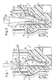
- the insulating body 2 is provided with an extension 5 which has a feed-through recess 6. Through the feed-through recess 6, wires 7 to be connected can be passed through, as can be seen in detail from FIGS. 1 and 2.
- connection block 1 has a connection contact 8 and a disconnection device 9.
- the connection contact 8 and the disconnecting device 9 are formed in one piece and together form an elastic spring clip 10.
- the respective clamp 10 is arranged in the associated receiving recess 3 of the insulating body 2.
- the receiving recess 3 has in particular a boundary wall 11, as shown in FIGS. 1 and 2, on the left-hand side, essentially perpendicular to the bottom surface of the insulating body 2, a bottom wall 12 adjoining it at right angles and a bottom wall 12 adjoining it at right angles Wall piece 13 on.
- the wall piece 13 merges at an obtuse angle upwards into a wall area 14 which forms a contact surface 15 pointing into the receiving recess 3.
- the function of this contact surface 15 will be described in more detail below.
- connection contact 8 has a rectilinearly extending, flat leg 18, which has a contact slot 19 in its upper region is provided. This contact slot 19 is used for contact-free contacting of the wire 7.
- the leg 18 is integrally connected to a U-shaped connecting piece 20.
- the connector 20 is also integrally connected at its other end to a flat leg part 21 which extends parallel to the leg 18 and which, like the parts still to be mentioned, is to be counted among the separating device 9.
- the leg part 21 is adjoined at the top by a convex region 22 which is bent at the upper end and has a knife slot 23.
- the lower end region 24 of the knife slot 23 - corresponding to FIG. 3 - is arranged higher than the lower end region 25 of the contact slot 19. Furthermore, it can be seen that the knife slot 23 and the Open contact slot 19 upwards so that they are easily accessible.
- FIGS. 1 and 2 illustrate that a conically widening insertion region 26 adjoins the contact slot 19 and the knife slot 23 at the top.
- the insertion area 26 is formed by two leg parts 27 and 28, which are arranged in one piece on the leg 18 and the bent area 22, respectively.
- an intermediate section 29 extending parallel to the leg 18 is arranged between the leg part 28 and the bent region 22.
- This section 29 has on its side facing the leg 18 a guide surface 30, which therefore on the Separating device 9 is arranged.
- This guide surface 30 is used to guide a one-legged wiring tool 31, which can be, for example, a conventional screwdriver with tapered side surfaces.
- a wiring tool 31 is also shown schematically in a slightly simplified manner in FIGS. 1 and 2.
- connection block 1 in the course of contacting the wire 7 becomes clear.
- the wire 7 is guided through the feed-through recess 6 into the area of the contact slot 19 and the knife slot 23. 1 with a part of it essentially horizontally in the insertion area 26. In this position, the leg 18 and the leg part 21 lie flat against the boundary wall 11 or the wall piece 13, whereas the bulged area 22 is at a certain distance from the contact surface 15 occupies.
- the wiring tool 31 If the wire 7 is to be contacted, the wiring tool 31 is moved in the direction of the double arrow 32 down towards the bottom of the receiving recess 3. As is clear from FIG. 2, the wiring tool 31 presses the wire 7 with its left-hand end into the contact slot 19, the insulation of the wire being severed and thus contact being made. The wiring tool 31 rests with its corresponding surface on the guide surface 30 of the separating device 9. Due to the conical design of the tip of the wiring tool 31, the bent region 22, which is connected to the leg 18 in a resilient manner via the leg part 21 and the connecting piece 20, is deflected and is supported on the contact surface 15.
- the wire end 34 of the contacted area of the wire 7, which end extends into the receiving recess 3, is bent over and thus lies against the inside of the leg 18. This improves the hold of the wire 7 in the contact slot 19, so that the contact is maintained even when a tensile load is applied.
- the wiring tool 31 is pulled upward in the direction of the double arrow 32 from the receiving recess 3, after which the disconnecting device 9 springs back into its position shown in FIG. 1.
- a modified bracket 10 is shown, which in principle can also be used in the connection block 1 according to FIGS. 1 and 2.
- the separating device of the clamp 10 in FIG. 3 points in contrast to 1 and 2 does not have an outwardly bent region 22.
- the connection contact 8, comprises the flat leg 18 already described above, to which the flat leg part 21 extends in parallel. These two legs 18 and 21 are also connected to one another in one piece via the connecting piece 20.
- the U-shaped connecting piece 20 is fastened to two narrow sides 35 and 36 of the legs 18 and 21 lying in a horizontal plane.
- the fastening areas of the connecting piece 20 on the narrow sides 35 and 36 lie somewhat above the lower edge of the legs 18 and 21, as can be seen in detail from FIG. 3.
- contact slot 19 is made wider in its upper end region and merges into the leg part 27 of the insertion region 26.
- the knife slot 23 is V-shaped according to FIG. 3, the lower end region 24 of the conically downwardly converging knife slot 23 again being higher than the end region 25 of the contact slot 19.
- the modified clamp 10 shown in FIG. 3 has an extension 37 that comes to rest in a correspondingly designed area of the connection block 1.
- the receiving recess 3 must also have an inclined contact surface 15 due to the resilient arrangement of the separating device 9 on the connection contact 8, to which the leg part 21 with its corresponding surface in the course of the train the introduction of the wiring tool 31 for stabilization.
- leg 18, starting from the end region 25 of the contact slot 19 is provided in the center with a separating slot which runs through the corresponding wall part to an essentially rectangular opening and which serves to increase the elasticity.
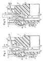
- connection block 1 ' comprises an insulating body 2', in which a receiving recess 3 'is provided.
- the receiving recess 3 ' has mutually parallel boundary walls 11', 13 'in a lower section.
- boundary wall 11 ' is in a thickened area to the bottom surface of the insulating body 2' parallel opening 38 is provided, which is above the approach 5 '.
- a bracket 10 ' is arranged within the recess 3', which has a connection contact 8 'and an integral clamping device 9' thereon.
- the connection contact 8 'and the clamping device 9' are connected to each other via an arcuate connector 20 '.
- the wire is only clamped to the device 9 ', in contrast to the arrangements described above, in which the device 9 is used to actually separate the wire.
- the clamping device 9 ' has at its lower end a projection 39, the free end of which projects into the opening 38 and is used for improved fixing. Furthermore, the clamping device 9 'has a clamping slot 40, which may preferably be designed to taper downwards. The clamping slot 40 passes in its upper region into an insertion opening 41 in the connector 20 '.
- connection contact 8 ' has an elongated, flat leg 18', in the upper region of which a contact slot 19 'is provided, which also merges into the insertion opening 41.
- the contact slot 19 ' extends obliquely to the overall direction of the connector 8' as such, whereby the contact legs of the contact slot 19 'form a torsion spring.
- the contact slot 19 ' is arranged in a sloping section adjoining a guide surface 30', as can be seen in particular from FIG. 6 in detail.
- the insertion opening 41 itself extends from a horizontal surface area of the connecting piece 20 'into an adjoining inclined surface section which is connected to the guide surface 30'. As can be seen from Fig. 6, the insertion opening 41 narrows just above the transition into the guide surface 30 ', which in the installed state for Bottom surface of the insulating body 2 'parallel edge is created for the separation of the wire insulation.
- a surface 42 'opposite the guide surface 30' is provided on the insulating body 2 '. This surface 42 is slightly inclined so that the guide surface 30 'and the opposite surface 42 define a tapered, upwardly opening receiving chamber 43.
- the incoming end of the wire 7 ' is fixed in the clamping slot 40, which results in the advantage in the contacted state that the clamping slot 40 also acts as a strain relief slot for the contacted wire 7'.
- the wire 7 'in the contact slot 19' is contacted by cutting the insulation. Due to the inclination of the contact slot 19 ', there is a positive notch of the edges of the contact tongues due to their torsional spring force in the material of the wire running approximately parallel to this in the bevels.
- connection block 1' also shows, by further pressing in the wiring tool 31 ', the wire is torn off, since it is fixed on the one hand in the clamping slot 40 of the clamping device 9' and, on the other hand, is clamped between the opposite surface 42 and the corresponding surface area of the wiring tool 31 '.
- the torn free end or the protruding wire length 33 'after the contacting and disconnection process can be removed from the connection block 1'.
- connection block 1 ⁇ in turn comprises an insulating body 2 ⁇ , in which a receiving recess 3 ⁇ is arranged.
- the receiving recess 3 ⁇ has a U-shaped cross section with parallel boundary walls 11 ⁇ , 13 ⁇ , which are connected to one another via a bottom wall 12 ⁇ .
- a shaft 47 is arranged in addition to this receiving recess 3 ⁇ .
- the insulating body 2 ⁇ also has a strip 48, which is arranged above the shoulder 5 ⁇ and is pulled outwards relative to a main region 49 of the insulating body 2 ⁇ .
- the strip 48 has an outer wall 50 which runs essentially parallel to the boundary wall 11 ⁇ . Its inner wall 51 forms an acute angle with the surface of the outer wall 50.
- the strip 48 also has a support surface 52 which extends substantially parallel to the bottom surface of the insulating body 2 ⁇ between the outer wall 50 and the inner wall 51.
- the clamp 10 ⁇ is U-shaped in its lower region arranged in the receiving recess 3 ⁇ , a holding part 53 having a defined holding edge 54 being arranged on a leg part 21 ⁇ of the clamping device 9 ⁇ above the recess 3 ⁇ .
- a contact slot 19 ⁇ is provided above the leg 18 ⁇ of the connection contact, the lower end region 25 Scheme thereof being lower than the holding edge 54.
- an essentially L-shaped extension piece 55 which can be integrally connected to the leg 18 ⁇ .
- the design and arrangement of the extension piece 55 can be seen in detail in FIG. 7. It can serve for further support of the clamp 10 ⁇ and for contacting further connections in the connection block 1 ⁇ .
- a guide surface 30 ⁇ is provided for a wiring tool 31 ⁇ , which in turn can be designed as a screwdriver provided with a conical tip.
- the guide surface 30 ⁇ and the inner wall 51 thereby delimit a receiving chamber 43 ⁇ .
- Fig. 7 the state is shown in which a wire 7 'is inserted into the bracket or into the contact slot 19' of the connection contact 8 '. From this illustration it is clear that the wire 7 'rests on the support surface 52 and is pressed into the receiving chamber 43' by the wiring tool 31 '. Here, a surface of the wiring tool 31 ⁇ bears against the guide surface 30 ⁇ , as is shown in detail in FIG. 7. As a result, the non-stripped wire 7 ⁇ is contacted in the contact slot 19 ⁇ . The wire 7 ⁇ is pressed and fixed on the retaining edge 54. The free end is inserted into the shaft 47. In this embodiment, the wire to be connected must be cut to length before contacting.
- the clamping device 9 ⁇ is arranged resiliently on the connection contact 8 ⁇ , and since the holding part 53 is also slightly inclined relative to the leg part 21 ⁇ in the direction of the shaft 47, the leg part 21 ⁇ is pressed onto the wall piece 13 ⁇ during the clamping operation and attaches in doing so. As a result, the clamp 10 ⁇ experiences increased stabilization, which in turn prevents undesired evasion or buckling. This is further increased by the contact of the leg 18 ⁇ on the longitudinal boundary wall 11 ⁇ of the receiving recess 3 ⁇ .
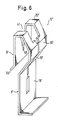
- FIG. 8 the clip that is used in the connection block 1 ⁇ shown in FIG. 7 is shown again in perspective, the extension piece 55 is not shown in part for reasons of clarity. 8, the position of the contact slot 19 Sch in the leg 18 ⁇ is particularly clear. Furthermore, it is shown that at the top of the contact slot 19 ⁇ there is an enlarged insertion opening 41 ⁇ with respect to this, which also extends into the part of the extension piece 55 directly adjoining the leg 18 ⁇ .
- connection block 1 ′′′ has an insulating body 2 ′′′, which is provided with receiving recesses 3 ′′′.
- connection block 1 ′′′ has a connection contact 8 ′′′ and a disconnecting device 9 ′′′, which are formed in one piece and together form an elastic spring clip 10 ′′′.
- the bracket 10 ′′′ is arranged in the associated receiving recess 3 ′′′ of the insulating body 2 ′′′.
- the receiving recess 3 ′′′ is adapted to the special shape of the bracket 10 ′′′, which can be seen in detail in FIG. 9.
- the parts corresponding to the previous embodiments are provided with indexed identical reference numerals.
- the insulating body 2 ′′′ is symmetrical with respect to the central plane M and has insertion openings for wires in its respective upper edge regions, of which the insertion opening 56 is visible in FIG. 9.
- insertion opening 56 has a hinged lid 57 arranged so that it can pivot, the left hinged lid 57 shown in FIG. 9 being shown in the pivoted-away state.
- these can be attached to the insulating body 2 2 with a suitable hinge or pivoting device.
- Insertion openings are arranged in the hinged covers 57, of which the insertion opening 58 is shown in FIG. 9.
- a screwdriver can be inserted through the insertion opening 58 into the insulating body 2 ′′′ for contacting and disconnecting a wire, as has already been described in detail above with reference to the preceding embodiments of the connection block according to the invention.
- Fig. 10 shows the structure of the bracket 10 ′′′ in perspective, from which it is clear that the bracket 10 ′′′ is symmetrical. Accordingly, the following description of one symmetry half of the bracket 10 ammer also applies to the other symmetry half.
- the clamp 10 ′′′ has a plate-shaped main part 60, on which the connection contact 8 ′′′ is arranged essentially at a right angle.
- the connection contact 8 ′′′ is designed as an insulation displacement contact, which comprises a flat leg 61 which merges into an inwardly curved, approximately V-shaped extension part 62.
- an essentially U-shaped insertion opening 63 is arranged, which merges into an insulation displacement slot 64, which ends approximately in the middle of the leg 61.
- a contact and guide surface 65 is provided below of the extension part 62 is arranged.
- the contact and guide surface 65 is connected to the lower end region of the leg 61 via a connecting section 66.
- a connecting section 66 Above the connecting section 66 there is a slot 67 which separates the upper part of the contact and guide surface from the leg 61 and which tapers upwards towards the extension part.
- the contact and guide surface 65 also has two upper edge regions 68 and 69 arranged at an acute angle to one another.
- the edge region 69 merges into a stop strip 70 which is essentially rectangular in shape and projects from the contact and guide surface parallel to the leg 61 from the contact and guide surface 65 in the same direction as the leg 61.
- a shear strip 71 is provided above the stop strip 70.
- the shear strip 71 projects in the same direction as the stop strip 70 and is arranged on a wall section 72 which lies in the same plane as the contact and guide surface 65.
- the stepped position of the shear strip 71 and the stop strip 70 resulting from the arrangement described above can be seen in particular from FIG. 9. It should also be emphasized that the parts 61 and 65 to 72 of the bracket 10 ′′′ are integrally formed on one another. Here, the stop strip 70 and the shear strip 71 can be produced by angling.
- a substantially inverted V-shaped recess 73 is arranged in the main part 60 of the bracket 10 ′′′ below the stop strip 70, in which a correspondingly formed projection 74 of the insulating body 2 ′′′ engages to secure the position when the bracket 10 ′′′. is inserted in the insulating body 2 ′′′.
- This arrangement is illustrated in FIG. 9.
- FIG. 9 shows that, depending on the position of the stop strip 70 and the shear strip 71 in the insulating body 2 ′′′, two shoulders 75 and 76 are formed, on which the shear strip 71 and the stop strip 70 in the inserted state of the clamp 10 ′′′ lie on.
- a web 77 projecting in the same direction as the shear strip 71, integrally adjoins the wall section 72 substantially at right angles, which in turn tapers into the median plane M at an acute angle according to FIG. 9
- Leg 78 merges.
- a further leg 79 lying essentially parallel to the central plane M is arranged on the leg 78.
- the legs 78 and 79 form a separating contact 82 with the symmetrically arranged legs 80 and 81, the upper region of which is delimited by the legs 78 and 80 and is V-shaped, while the legs 79 and 81 are substantially parallel below Delimitation of a gap to each other.
- the contact legs 79 and 81 each carry a vertical or horizontal contact bead, which together form a normally closed contact.
- Fig. 10 illustrates here that the legs 79 and 81 are provided with a contact stamping 85.
- a connecting wall section 83 in which one Separation 84 shown in dashed lines in FIG. 10 can be attached.
- Such a separation or opening 84 can be produced by punching out the corresponding wall section, which only enables the connected wires to be connected through the two legs 79 and 81 of the isolating contact 82.
- a wire is to be contacted in the embodiment of the connection block 1 ′′′ according to FIG. 9, this is inserted into the interior of the insulating body 2 ′′′, after which a commercially available screwdriver is inserted through the opening 58.
- This can contact the contact and guide surface 65 and possibly adjacent housing parts of the insulating body 2 ′′′ and contacts the wire in the insulation displacement slot 64 in the course of the pressing down.
- the excess length is cut off at the shear strip 71 because the underneath the insertion opening 58 in the insulating body 2 ′′′ formed V-shaped chamber 86 only offers space for the one-leg wiring tool in the form of a screwdriver 87, but not for the wire.
- the illustration in FIG. 9 shows that the design of the chamber 86 is selected so that it fits exactly with the screwdriver 87, so that the desired function is ensured.
- the separating device from the shear strip 71 and the stop strip 70 is formed, which are also integrally connected to the connection contact 8 Kunststoff to form the clamp 10 'and enable the use of a simple screwdriver as a wiring tool.
- the additional disconnection option further expands the adaptation options of the embodiment according to FIGS. 9 and 10. Otherwise, this embodiment also has all advantages that have been explained above in connection with the other embodiments.
Landscapes
- Connections By Means Of Piercing Elements, Nuts, Or Screws (AREA)
- Connections Arranged To Contact A Plurality Of Conductors (AREA)
- Multi-Conductor Connections (AREA)
- Cable Accessories (AREA)
- Details Of Connecting Devices For Male And Female Coupling (AREA)
- Structure Of Telephone Exchanges (AREA)
- Coupling Device And Connection With Printed Circuit (AREA)
- Communication Cables (AREA)
Priority Applications (1)
| Application Number | Priority Date | Filing Date | Title |
|---|---|---|---|
| AT8989108935T ATE105112T1 (de) | 1988-05-31 | 1989-05-18 | Anschlussblock fuer eine kabelabschlusseinheit. |
Applications Claiming Priority (2)
| Application Number | Priority Date | Filing Date | Title |
|---|---|---|---|
| DE3818497A DE3818497C5 (de) | 1988-05-31 | 1988-05-31 | Anschlußblock für eine Kabelabschlußeinheit |
| DE3818497 | 1988-05-31 |
Publications (4)
| Publication Number | Publication Date |
|---|---|
| EP0344526A2 true EP0344526A2 (fr) | 1989-12-06 |
| EP0344526A3 EP0344526A3 (en) | 1990-10-24 |
| EP0344526B1 EP0344526B1 (fr) | 1994-04-27 |
| EP0344526B2 EP0344526B2 (fr) | 1997-09-10 |
Family
ID=6355516
Family Applications (1)
| Application Number | Title | Priority Date | Filing Date |
|---|---|---|---|
| EP89108935A Expired - Lifetime EP0344526B2 (fr) | 1988-05-31 | 1989-05-18 | Bloc de jonction pour unité de terminaison de câbles |
Country Status (8)
| Country | Link |
|---|---|
| US (1) | US5118305A (fr) |
| EP (1) | EP0344526B2 (fr) |
| JP (1) | JP2982963B2 (fr) |
| AT (1) | ATE105112T1 (fr) |
| CA (1) | CA1305227C (fr) |
| DE (2) | DE3818497C5 (fr) |
| NO (1) | NO892182L (fr) |
| PT (1) | PT90703B (fr) |
Cited By (5)
| Publication number | Priority date | Publication date | Assignee | Title |
|---|---|---|---|---|
| DE4131822C1 (en) * | 1991-09-20 | 1992-06-11 | Krone Ag, 1000 Berlin, De | Contact element with cutting clamp - has cut=outs forming contact slot in front and rear walls of metal strip material |
| EP0613219A1 (fr) * | 1993-02-26 | 1994-08-31 | Quante Aktiengesellschaft | Outil de câblage pour des conducteurs isolés |
| EP0554810A3 (en) * | 1992-02-07 | 1996-04-24 | Harting Elektronik Gmbh | Electrical connector |
| EP2144331A1 (fr) | 2008-07-11 | 2010-01-13 | Reichle & De-Massari AG | Contact à déplacement d'isolation et dispositif de connexion |
| SE2450270A1 (en) * | 2024-03-08 | 2025-09-09 | Eltelligent Ab | Insulation removing connection device and arrangement for electrical wires |
Families Citing this family (10)
| Publication number | Priority date | Publication date | Assignee | Title |
|---|---|---|---|---|
| US5643004A (en) * | 1992-09-04 | 1997-07-01 | Quante Aktiengesellschaft | Electric connection contact in a single piece |
| DE9211917U1 (de) * | 1992-09-04 | 1992-11-12 | Quante AG, 5600 Wuppertal | Einstückiger Anschlußkontakt |
| DE4312781C2 (de) * | 1993-04-20 | 1995-10-19 | Vossloh Schwabe Gmbh | Anschlußelement für wenigstens ein elektrisches Betriebsmittel |
| DE4437022C1 (de) * | 1994-10-08 | 1996-02-22 | Krone Ag | Anschlußelement |
| DE19541137A1 (de) * | 1995-10-30 | 1997-05-07 | Wago Verwaltungs Gmbh | Elektr. Frontverdrahtungsklemme |
| ID21145A (id) * | 1997-05-15 | 1999-04-29 | Reichle & De Massari Fa | Terminal pengkabelan untuk pengkabelan penjepit-potong bebas-solder dari konduktor elektrik terisolasi |
| ATE529920T1 (de) * | 2004-04-23 | 2011-11-15 | Tyco Electronics Amp Es Sa | Kappe, abschlussbaugruppe und gehäusebaugruppe für einen modularen telekom-verbindungsstecker |
| FR2871299B1 (fr) * | 2004-06-03 | 2006-08-11 | Legrand Sa | Accessoire de denudage d'un conducteur electrique isole et borne de connexion auto-denudante comprenant un tel accessoire |
| EP2665128B1 (fr) | 2012-05-14 | 2017-12-13 | TE Connectivity Germany GmbH | Élément de contact IDC destiné à une fiche électrique |
| EP3657604A1 (fr) | 2018-11-26 | 2020-05-27 | TE Connectivity Germany GmbH | Ensemble de terminaison de câble avec des lames de coupe électriquement isolantes |
Family Cites Families (11)
| Publication number | Priority date | Publication date | Assignee | Title |
|---|---|---|---|---|
| IL33234A (en) * | 1968-11-18 | 1973-05-31 | Amp Inc | Wire insertion device |
| CA981352A (en) * | 1972-04-08 | 1976-01-06 | Roberto Plana | Electrical connectors |
| DE3021798C2 (de) * | 1980-06-11 | 1982-03-11 | Krone Gmbh, 1000 Berlin | Vorrichtung und Verfahren zur Herstellung eines Doppelkontaktes an einem löt-, schraub- und abisolierfreiem Klemmverbinder |
| DE3122303A1 (de) * | 1981-06-04 | 1983-01-27 | Felten & Guilleaume Energietechnik GmbH, 5000 Köln | Federklemme zum anschluss isolierter elektrischer leiter |
| DE3137429C2 (de) * | 1981-09-19 | 1984-03-22 | Krone Gmbh, 1000 Berlin | Anschlußeinrichtung in einer Anschlußleiste |
| FR2516711A1 (fr) * | 1981-11-17 | 1983-05-20 | Alsthom Cgee | Borne de raccordement de fil electrique sans denudage |
| US4552429A (en) * | 1984-10-01 | 1985-11-12 | Amp Incorporated | Modular electrical connector for connecting wires in cable ends |
| DE3509523C3 (de) * | 1985-03-16 | 1996-07-04 | Quante Ag | Kabelabschlußeinheit |
| DE3711675A1 (de) * | 1987-04-07 | 1988-10-27 | Krone Ag | Aderverbinder fuer kabeladern, insbesondere von fernmeldekabeln |
| US4781618A (en) * | 1987-06-25 | 1988-11-01 | Reed Devices, Inc. | Pushbutton electrical terminal |
| US4768976A (en) * | 1987-08-06 | 1988-09-06 | Bruno Gelati | Electrical connector |
-
1988
- 1988-05-31 DE DE3818497A patent/DE3818497C5/de not_active Expired - Lifetime
-
1989
- 1989-05-18 AT AT8989108935T patent/ATE105112T1/de not_active IP Right Cessation
- 1989-05-18 DE DE58907547T patent/DE58907547D1/de not_active Expired - Fee Related
- 1989-05-18 EP EP89108935A patent/EP0344526B2/fr not_active Expired - Lifetime
- 1989-05-29 CA CA000601008A patent/CA1305227C/fr not_active Expired - Fee Related
- 1989-05-30 NO NO89892182A patent/NO892182L/no unknown
- 1989-05-31 JP JP1139009A patent/JP2982963B2/ja not_active Expired - Fee Related
- 1989-06-01 PT PT90703A patent/PT90703B/pt not_active IP Right Cessation
-
1991
- 1991-05-15 US US07/701,589 patent/US5118305A/en not_active Expired - Lifetime
Cited By (8)
| Publication number | Priority date | Publication date | Assignee | Title |
|---|---|---|---|---|
| DE4131822C1 (en) * | 1991-09-20 | 1992-06-11 | Krone Ag, 1000 Berlin, De | Contact element with cutting clamp - has cut=outs forming contact slot in front and rear walls of metal strip material |
| EP0554810A3 (en) * | 1992-02-07 | 1996-04-24 | Harting Elektronik Gmbh | Electrical connector |
| EP0613219A1 (fr) * | 1993-02-26 | 1994-08-31 | Quante Aktiengesellschaft | Outil de câblage pour des conducteurs isolés |
| EP2144331A1 (fr) | 2008-07-11 | 2010-01-13 | Reichle & De-Massari AG | Contact à déplacement d'isolation et dispositif de connexion |
| CH699105A1 (de) * | 2008-07-11 | 2010-01-15 | Reichle & De Massari Fa | Schneidklemmkontakt und Kontaktierungsvorrichtung. |
| US7857655B2 (en) | 2008-07-11 | 2010-12-28 | Reichle & De-Massari Ag | Insulation displacement contact and contacting device |
| SE2450270A1 (en) * | 2024-03-08 | 2025-09-09 | Eltelligent Ab | Insulation removing connection device and arrangement for electrical wires |
| SE547588C2 (en) * | 2024-03-08 | 2025-10-21 | Eltelligent Ab | Insulation removing connection device and arrangement for electrical wires |
Also Published As
| Publication number | Publication date |
|---|---|
| EP0344526A3 (en) | 1990-10-24 |
| EP0344526B1 (fr) | 1994-04-27 |
| PT90703A (pt) | 1989-12-29 |
| DE58907547D1 (de) | 1994-06-01 |
| DE3818497C2 (de) | 1996-03-28 |
| ATE105112T1 (de) | 1994-05-15 |
| CA1305227C (fr) | 1992-07-14 |
| US5118305A (en) | 1992-06-02 |
| NO892182D0 (no) | 1989-05-30 |
| DE3818497A1 (de) | 1989-12-14 |
| JPH02112171A (ja) | 1990-04-24 |
| DE3818497C5 (de) | 2005-05-25 |
| EP0344526B2 (fr) | 1997-09-10 |
| PT90703B (pt) | 1994-02-28 |
| JP2982963B2 (ja) | 1999-11-29 |
| NO892182L (no) | 1989-12-01 |
Similar Documents
| Publication | Publication Date | Title |
|---|---|---|
| EP0730785B1 (fr) | Borne de connexion pour installations electriques | |
| DE4423220C2 (de) | Unterbrechungsmechanismus für eine Dunkelstromsicherung | |
| EP0344526B1 (fr) | Bloc de jonction pour unité de terminaison de câbles | |
| DE1765818C3 (de) | Verbindungsklemme zum Andrücken an elektrische Drähte | |
| DE69022199T2 (de) | Torsionsschneidklemmverbinder. | |
| EP0283427A2 (fr) | Contact tubulaire tranchant à serrage | |
| EP0823752A2 (fr) | Connecteur à ressort pour conducteur électrique | |
| DE2735838C2 (de) | Elektrische Anschlußklemme und elektrisches Kabelverbindungsglied | |
| WO1999013533A1 (fr) | Contact enfichable | |
| DE2342408A1 (de) | Elektrisches klemmanschlusstueck | |
| WO1999012233A1 (fr) | Borne serre-fils pour le raccordement sans denudage de conducteurs isoles | |
| DE102020100333B3 (de) | Klemmfeder und Leiteranschlussklemme | |
| EP0267145B1 (fr) | Borne à découpage et serrage pour conducteur électrique | |
| DE3618108C2 (fr) | ||
| EP0038494A1 (fr) | Support de contact | |
| DE10232256B4 (de) | Klemmfedervorichtung für eine Federkraftklemme | |
| EP0424806B1 (fr) | Dispositif pour fixer un organe de connexion électrique et/ou mécanique, notamment un ressort de contact | |
| DE102018206849B4 (de) | Vorrichtung zur klemmenden Befestigung | |
| DE19909825C5 (de) | Hülsenförmiges Klemmelement zum abisolierfreien Anschluß elektrischer Leiter | |
| EP0993689B1 (fr) | Dispositif de connexion pour conducteurs electriques isoles non denudes | |
| EP3855572A1 (fr) | Borne de liaison | |
| DE10205613B4 (de) | Kontaktelement | |
| DE8702252U1 (de) | Hochspannungsbauteil | |
| EP1420481A1 (fr) | Elément de raccordement | |
| DE1765478A1 (de) | Federklemme zur Verbindung elektrischer Leiter |
Legal Events
| Date | Code | Title | Description |
|---|---|---|---|
| PUAI | Public reference made under article 153(3) epc to a published international application that has entered the european phase |
Free format text: ORIGINAL CODE: 0009012 |
|
| AK | Designated contracting states |
Kind code of ref document: A2 Designated state(s): AT BE CH DE ES FR GB IT LI NL SE |
|
| RIN1 | Information on inventor provided before grant (corrected) |
Inventor name: TENHAM, HORST-HELMUT Inventor name: HELL, ERICH Inventor name: ROTT, JOACHIM Inventor name: OTTO, HANS-DIETER |
|
| PUAL | Search report despatched |
Free format text: ORIGINAL CODE: 0009013 |
|
| AK | Designated contracting states |
Kind code of ref document: A3 Designated state(s): AT BE CH DE ES FR GB IT LI NL SE |
|
| 17P | Request for examination filed |
Effective date: 19901211 |
|
| 17Q | First examination report despatched |
Effective date: 19930817 |
|
| GRAA | (expected) grant |
Free format text: ORIGINAL CODE: 0009210 |
|
| AK | Designated contracting states |
Kind code of ref document: B1 Designated state(s): AT BE CH DE ES FR GB IT LI NL SE |
|
| PG25 | Lapsed in a contracting state [announced via postgrant information from national office to epo] |
Ref country code: IT Free format text: LAPSE BECAUSE OF FAILURE TO SUBMIT A TRANSLATION OF THE DESCRIPTION OR TO PAY THE FEE WITHIN THE PRESCRIBED TIME-LIMIT;WARNING: LAPSES OF ITALIAN PATENTS WITH EFFECTIVE DATE BEFORE 2007 MAY HAVE OCCURRED AT ANY TIME BEFORE 2007. THE CORRECT EFFECTIVE DATE MAY BE DIFFERENT FROM THE ONE RECORDED. Effective date: 19940427 Ref country code: ES Free format text: THE PATENT HAS BEEN ANNULLED BY A DECISION OF A NATIONAL AUTHORITY Effective date: 19940427 |
|
| REF | Corresponds to: |
Ref document number: 105112 Country of ref document: AT Date of ref document: 19940515 Kind code of ref document: T |
|
| PG25 | Lapsed in a contracting state [announced via postgrant information from national office to epo] |
Ref country code: SE Effective date: 19940519 |
|
| PG25 | Lapsed in a contracting state [announced via postgrant information from national office to epo] |
Ref country code: LI Effective date: 19940531 Ref country code: CH Effective date: 19940531 |
|
| REF | Corresponds to: |
Ref document number: 58907547 Country of ref document: DE Date of ref document: 19940601 |
|
| GBT | Gb: translation of ep patent filed (gb section 77(6)(a)/1977) |
Effective date: 19940505 |
|
| ET | Fr: translation filed | ||
| PG25 | Lapsed in a contracting state [announced via postgrant information from national office to epo] |
Ref country code: GB Effective date: 19940727 |
|
| PLBI | Opposition filed |
Free format text: ORIGINAL CODE: 0009260 |
|
| 26 | Opposition filed |
Opponent name: KRONE AG Effective date: 19941203 |
|
| EUG | Se: european patent has lapsed |
Ref document number: 89108935.1 Effective date: 19950110 |
|
| REG | Reference to a national code |
Ref country code: CH Ref legal event code: PL |
|
| EUG | Se: european patent has lapsed |
Ref document number: 89108935.1 |
|
| NLR1 | Nl: opposition has been filed with the epo |
Opponent name: KRONE AG |
|
| GBPC | Gb: european patent ceased through non-payment of renewal fee |
Effective date: 19940727 |
|
| PLAW | Interlocutory decision in opposition |
Free format text: ORIGINAL CODE: EPIDOS IDOP |
|
| PLAW | Interlocutory decision in opposition |
Free format text: ORIGINAL CODE: EPIDOS IDOP |
|
| PLAW | Interlocutory decision in opposition |
Free format text: ORIGINAL CODE: EPIDOS IDOP |
|
| PUAH | Patent maintained in amended form |
Free format text: ORIGINAL CODE: 0009272 |
|
| STAA | Information on the status of an ep patent application or granted ep patent |
Free format text: STATUS: PATENT MAINTAINED AS AMENDED |
|
| 27A | Patent maintained in amended form |
Effective date: 19970910 |
|
| AK | Designated contracting states |
Kind code of ref document: B2 Designated state(s): AT BE CH DE ES FR GB IT LI NL SE |
|
| REG | Reference to a national code |
Ref country code: CH Ref legal event code: AEN Free format text: AUFRECHTERHALTUNG DES PATENTES IN GEAENDERTER FORM |
|
| ET3 | Fr: translation filed ** decision concerning opposition | ||
| NLR2 | Nl: decision of opposition | ||
| NLR3 | Nl: receipt of modified translations in the netherlands language after an opposition procedure | ||
| PGFP | Annual fee paid to national office [announced via postgrant information from national office to epo] |
Ref country code: FR Payment date: 19990512 Year of fee payment: 11 |
|
| PGFP | Annual fee paid to national office [announced via postgrant information from national office to epo] |
Ref country code: NL Payment date: 19990531 Year of fee payment: 11 Ref country code: AT Payment date: 19990531 Year of fee payment: 11 |
|
| PGFP | Annual fee paid to national office [announced via postgrant information from national office to epo] |
Ref country code: BE Payment date: 19990623 Year of fee payment: 11 |
|
| PG25 | Lapsed in a contracting state [announced via postgrant information from national office to epo] |
Ref country code: AT Free format text: LAPSE BECAUSE OF NON-PAYMENT OF DUE FEES Effective date: 20000518 |
|
| PG25 | Lapsed in a contracting state [announced via postgrant information from national office to epo] |
Ref country code: BE Free format text: LAPSE BECAUSE OF NON-PAYMENT OF DUE FEES Effective date: 20000531 |
|
| BERE | Be: lapsed |
Owner name: QUANTE A.G. Effective date: 20000531 |
|
| PG25 | Lapsed in a contracting state [announced via postgrant information from national office to epo] |
Ref country code: NL Free format text: LAPSE BECAUSE OF NON-PAYMENT OF DUE FEES Effective date: 20001201 |
|
| PG25 | Lapsed in a contracting state [announced via postgrant information from national office to epo] |
Ref country code: FR Free format text: LAPSE BECAUSE OF NON-PAYMENT OF DUE FEES Effective date: 20010131 |
|
| NLV4 | Nl: lapsed or anulled due to non-payment of the annual fee |
Effective date: 20001201 |
|
| REG | Reference to a national code |
Ref country code: FR Ref legal event code: ST |
|
| PGFP | Annual fee paid to national office [announced via postgrant information from national office to epo] |
Ref country code: DE Payment date: 20070702 Year of fee payment: 19 |
|
| PG25 | Lapsed in a contracting state [announced via postgrant information from national office to epo] |
Ref country code: DE Free format text: LAPSE BECAUSE OF NON-PAYMENT OF DUE FEES Effective date: 20081202 |