EP0424806B1 - Dispositif pour fixer un organe de connexion électrique et/ou mécanique, notamment un ressort de contact - Google Patents
Dispositif pour fixer un organe de connexion électrique et/ou mécanique, notamment un ressort de contact Download PDFInfo
- Publication number
- EP0424806B1 EP0424806B1 EP90120001A EP90120001A EP0424806B1 EP 0424806 B1 EP0424806 B1 EP 0424806B1 EP 90120001 A EP90120001 A EP 90120001A EP 90120001 A EP90120001 A EP 90120001A EP 0424806 B1 EP0424806 B1 EP 0424806B1
- Authority
- EP
- European Patent Office
- Prior art keywords
- spring strip
- spring
- contact
- opening
- arrangement according
- Prior art date
- Legal status (The legal status is an assumption and is not a legal conclusion. Google has not performed a legal analysis and makes no representation as to the accuracy of the status listed.)
- Expired - Lifetime
Links
Images


Classifications
-
- H—ELECTRICITY
- H01—ELECTRIC ELEMENTS
- H01R—ELECTRICALLY-CONDUCTIVE CONNECTIONS; STRUCTURAL ASSOCIATIONS OF A PLURALITY OF MUTUALLY-INSULATED ELECTRICAL CONNECTING ELEMENTS; COUPLING DEVICES; CURRENT COLLECTORS
- H01R4/00—Electrically-conductive connections between two or more conductive members in direct contact, i.e. touching one another; Means for effecting or maintaining such contact; Electrically-conductive connections having two or more spaced connecting locations for conductors and using contact members penetrating insulation
- H01R4/28—Clamped connections, spring connections
- H01R4/48—Clamped connections, spring connections utilising a spring, clip, or other resilient member
-
- H—ELECTRICITY
- H01—ELECTRIC ELEMENTS
- H01R—ELECTRICALLY-CONDUCTIVE CONNECTIONS; STRUCTURAL ASSOCIATIONS OF A PLURALITY OF MUTUALLY-INSULATED ELECTRICAL CONNECTING ELEMENTS; COUPLING DEVICES; CURRENT COLLECTORS
- H01R4/00—Electrically-conductive connections between two or more conductive members in direct contact, i.e. touching one another; Means for effecting or maintaining such contact; Electrically-conductive connections having two or more spaced connecting locations for conductors and using contact members penetrating insulation
- H01R4/58—Electrically-conductive connections between two or more conductive members in direct contact, i.e. touching one another; Means for effecting or maintaining such contact; Electrically-conductive connections having two or more spaced connecting locations for conductors and using contact members penetrating insulation characterised by the form or material of the contacting members
- H01R4/64—Connections between or with conductive parts having primarily a non-electric function, e.g. frame, casing, rail
Definitions
- the invention relates to an arrangement for fixing a mechanical and / or electrical connecting element, in particular a contact spring, according to the preamble of patent claim 1.
- the invention has for its object to provide an arrangement for fixing a mechanical and / or electrical connecting element, which is simpler in construction, inexpensive to manufacture and is nevertheless held securely on a sheet metal wall.
- the connecting element is not only securely attached to the To hold the sheet metal wall, but also to be able to detach it from the sheet metal wall. Due to its at least partial resting on a transverse web dividing the receiving opening into two opening sections, the ends of the spring strip are pressed into the respective one Opening section particularly easily possible, since the support of the spring strip on the crossbar allows the spring strip to bend in the transverse direction and thus allows the ends to be pressed in easily. When the spring strip is bent in the transverse direction, the ends are therefore arranged in the pressing-in direction in front of the section of the spring strip which is supported on the transverse web.
- each end of the spring strip Since the width of the ends of the spring strip is slightly larger than the width of the respective opening section, each end is firmly clamped in the corresponding opening section, so that the spring strip and thus the connecting element are held firmly on the sheet metal wall.
- a setting movement acting in the longitudinal and transverse directions occurs shortly after the pushing-in process, through which the spring strip cuts into the receiving opening and expands in it.
- This setting movement enables not only good electrical contact and thus shielding, but also permanent anchoring of the spring strip in the opening sections of the receiving opening, so that the connecting element connected to the spring strip can be used for electrical and / or mechanical purposes.
- the increasing width of the ends in the direction of the respective longitudinal end of the spring strip enables a contact pressure which increases with the width, so that the outer section of the ends is still held firmly in the respective opening section when the axially inner section of the ends nods more firmly the opening portion is fixed.
- the longitudinal ends of the spring strip each have a central notch, which facilitate the reception of the spring strip in a tool for pressing in the ends.
- this can result in more favorable stress curves at the ends due to the deflection of the spring strip in the transverse direction and the ends in the longitudinal direction.
- the arrangement to fix an electrical contact spring to the sheet metal wall, which is connected in one piece to the middle section of the spring strip connecting the ends.
- the middle section therefore serves in the sense of a double action both for connecting the ends and for receiving the contact spring.
- This embodiment therefore consists of only one part that can be produced very inexpensively and inserted into the receiving opening.
- the manufacture of such an arrangement is particularly simple if the contact spring is a spring arm which extends transversely to the longitudinal direction of the spring strip, since this can easily be provided on one of the free sides of the central section.
- the feature of forming the outer surface of the spring arm as a smooth contact surface is also favorable, in order thereby to achieve an uninterrupted ground connection on the contact spring side and thus good electrical shielding.
- the further embodiment of the invention is also favorable, in which an electrical contact plate forming the connecting element is formed by the section of the spring strip connecting the ends.
- the middle section therefore serves in the sense of a double action both for connecting the ends of the spring strip and as a contact plate for establishing a ground connection.
- the spring strip can thus serve on the one hand to receive the connecting element and on the other hand, as such, be a contact plate.
- it is the same spring strip, so that its production can be carried out rationally and inexpensively for both applications because of the formation of only one part.
- the middle section of the spring strip is advantageously considerably wider than its ends, so that a large contact area is available for receiving a counter-contact element.
- such a contact plate is securely supported on the crossbar and on the part of the sheet metal wall delimiting the receiving opening by means of the central section.
- a tool for pressing the ends of a spring strip of a fixing arrangement into a receiving opening which has two pressing jaws which receive the spring strip in the longitudinal direction between them, between which a recess is formed which allows the spring strip to bend.
- the ends of the spring strip can rest when the middle section of the The spring strip on the crossbar can be easily pressed into the respective opening section.
- Fixing the spring strip is particularly simple if each press-in jaw has a central, inward projection that fits into the respective notch of the spring strip.
- a spring strip provided with such a notch is securely held in the longitudinal direction by the press-in jaws and in the transverse direction by means of the projections engaging in the respective notches.
- the recess provided between the press-in jaws also enables the spring strip carrying a connecting element to be received, which extends into the recess when the spring strip is inserted into the tool.
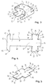
- FIGS. 1, 2 and 6, 7 show an arrangement 1 for fixing a mechanical and / or electrical connecting element 2 in the region of a receiving opening 3 on a sheet metal wall 4.
- the connecting element 2 is designed as a contact spring 5.
- the receiving opening 3 is divided by a crosspiece 6 into two opening sections 10, 11, which are rectangular in FIGS. 1, 2 and 6, 7.
- the contact spring 5 is carried by an elongated spring strip 12, which consists of two opposite ends 13, 14 and a middle section 15 connecting the ends.
- the ends 13, 14 can be pressed into one of the opening sections 10, 11 when the middle section 15 rests on the crossbar 6, so that the length of the spring strip 12 exceeds the width of the crossbar 6 and the width of the ends 13, 14 is slightly larger is the width of the respective opening section 10, 11.
- the central section 15 of the spring strip 12 lies at least partially on the transverse web 6, in particular on its longitudinal edges 16, 17.
- the central section 15 is slightly longer than the width of the transverse web 6 extending between the longitudinal edges 16, 17.
- the ends 13, 14 in the longitudinal direction of the spring strip 12 are bent in the middle at 21 to form a V-shape 20 that opens against the direction of insertion.
- the longitudinal ends 22, 23 (see FIG. 4) of the spring strip 12 each have a central notch 24, 25 which is approximately semicircular.
- approximately semicircular incisions 26 to 29 are provided so that the width of the ends 13, 14 is smaller in this area than between the longitudinal sides 32 to 35 of the ends 13, 14 (see Fig. 4).
- the incisions 26 to 29 favor pressing the ends 13, 14 into the respective opening section 10, 11, since they support both the formation of the V-shape and a kinking of the entire ends 13, 14 in the pushing-in direction (see FIG. 2). 2 clearly shows that the transverse side 36, 37 of the ends carrying the respective notch 24, 25 is arranged deeper in the respective opening section 10, 11 in the pressing-in direction than the end of the longitudinal sides 32 to 35 near the incisions 26 to 29.
- the width of the ends 13, 14 in the direction of the respective longitudinal end 22, 23 of the spring strip 12 may increase, so that overall a dovetail-shaped end is formed.
- This embodiment favors an increase the transverse tension holding the spring strip in the respective opening section towards the longitudinal end of the spring strip and thereby preventing the spring strip from sliding out of the receiving opening, in particular in the region of the longitudinal ends of the spring strip.
- the arrangement 1 for fixing the electrical contact spring 5 is shown.
- This is connected in one piece to the central section 15 of the spring strip 12 and is designed as a spring arm 40 which extends transversely to the longitudinal direction of the spring strip.
- One end 41 is integrally connected to the central section 15, whereas the other end 42 is designed as a free end and approximately T-shaped.
- the section 43 of the T-shaped free end 42 extending parallel to the longitudinal direction of the spring strip 12 has at its ends completely or, as shown in dashed lines in FIG. 4, partially inclined edges 44, 45.
- the contact spring 5 is bent with its one end 41 approximately semicircularly from the central section 15 of the spring strip 12.
- the spring arm 40 is convex according to FIGS. 1 to 3, ie bent upwards in the figures, and has an outer surface 46; which is designed as a smooth contact surface. 1 to 3, the free end 42 of the spring arm 40 is bent approximately vertically in the direction of the spring strip such that at least the section 43 of the spring arm 40 is arranged below the spring strip 12 and the ends of section 43 with their obliquely running edges 44 , are angled towards the spring strip. 2, the sheet metal wall 4 is between the central section 15 and section 43 of the Spring arm 40 arranged, the former lying on the sheet metal wall and the latter below the sheet metal wall and this is arranged behind.
- the spring arm can first be kinked at its end 41 and then further out between the end 41 and the free end 42, i.e. 1 to 3 be angled upwards and straight in this area, i.e. not be convexly curved.
- the connecting element 2 is designed as an electrical contact plate 47, which is essentially formed by the central section 15 of the spring strip 12 connecting the ends 13, 14. 5 can completely correspond to that of FIG. 4, only the spring arm 40 which extends in the left half of FIG. 4 being omitted.
- the parts of the arrangement according to FIG. 5 therefore have the same reference numerals insofar as they correspond to those in the other figures. 1 to 5, the central section 15 of the spring strip 12 has a substantially greater width than its ends 13, 14, so that it can be supported on the sheet metal wall 4 delimiting the receiving opening 3 (see FIG. 2).
- FIGS. 6 and 7 each show an upper corner of the housing parts 50, 51, each of which has a horizontal section 52, 53 and a vertical section 54, 55 connected to it to have. 6, also mutually aligned receiving openings 3 are provided, in the case of the housing part 50, a spring strip 12 designed as a contact plate 47 and in the case of the housing part 51, a spring strip 12 carrying a contact spring 5 is.
- the two housing parts 50, 51 are connected to one another, for example, via a hinge joint, not shown.
- FIG. 7 is identical with respect to the housing part 51 to the embodiment shown in FIG. 6. Only the housing part 50 is designed differently in that rectangular, elongated contact surfaces 56, 57 are applied to the sections 52, 54 facing the housing part 51, which interact with the contact springs 5 and the spring strips 12 of the housing part 51.
- the housing parts 50, 51 When pivoting, for example, the right housing part 51 around the hinge joint, not shown, the housing parts 50, 51 finally abut one another, so that the respective contact surface of the spring arm 40 of the contact spring 5 with the contact surface of the contact plate 47 (see FIG. 6) or with the contact surfaces 56, 57 can cooperate.
- each contact spring 5 protrudes from the respective spring strip 12
- electrical contact and electrical shielding are also ensured if a gap is arranged between the two housing parts.
- the spring arms 40 are pivoted in the direction of the central section of the spring strip 12 such that each section 43 in FIGS. 6 and 7 moves to the right from the rear side 58 of the sheet metal wall 4 takes off.
- a connecting element not a contact spring, but any other element which is connected to the spring strip as flexibly as possible and protrudes therefrom.
- Such an element can also be a pin or a screw attached to the spring strip. It is only important that the maximum distance between the connecting element and the sheet metal wall corresponds at least to the (distance of the oppositely arranged contact surfaces in the assembled state of an electrical or electronic device.
- Contact spring or contact plate are designed so that the relative movement of the contact spring with respect to the The surface of the contact spring can be galvanically refined for safe contacting.
- the contact spring should also be highly elastic and be able to accommodate large housing gap tolerances with a soft spring characteristic. As shown in particular in FIGS.
- all receiving openings 3 are of identical design, so that both a spring strip forming the contact plate and a spring strip carrying the contact spring can be pressed into them strengths of the connecting elements and / or the spring strip can vary greatly and are not limited to thin spring steel plates. It is also possible to design the arrangement for fixing a mechanical and / or electrical connecting element as a holding device, in which a housing part by means of the arrangement e.g. can be held pivotably on the other arm part via hinge joints attached to the spring arm.
- a tool (not shown) for pushing in the ends 13, 14 of the spring strip 12 of the fixing arrangement 1 into a receiving opening 3 preferably consists of two spring strips 12 which receive spring strips 12 in the longitudinal direction between them, between which a recess is formed which allows the spring strip to bend.
- Each press-in jaw has a central, inward projection that fits into the notch in the spring strip.
- the spring strip with the associated contact spring is inserted between the press-in jaws of the tool in such a way that the spring arm of the contact spring extends into the recess between the press-in jaws and the respective projection of each press-in jaw engages in the corresponding recess in the longitudinal ends of the spring strip. Accordingly, the spring strip carrying the contact spring is arranged in the tool in such a way that it extends outwards and the contact spring extends toward the tool.
- the tool with the spring strip carrying the contact spring in the direction of the receiving opening 3 z. B. Fig. 1 performed.
- the pressing-in process takes place in such a way that the spring strip 12 is first placed on the receiving opening 3, the spring ends 13, 14 resting on the opening sections 10, 11 and the middle section 15 on the crosspiece 6.
- the respective end 13, 14 is pressed into the corresponding opening section 10, 11, the spring strip bending in the transverse direction and each end 13, 14 is additionally compressed in the longitudinal direction, ie along the central kink, in such a way that the angle 60 of the V-shape that opens against the direction of insertion is slightly reduced (see FIG. 2).
- the spring strip 12 When the spring strip 12 is bent in the transverse direction, it lies primarily on the longitudinal edges 16, 17 of the cross piece 6.
- the section 43 of the spring arm 40 slides horizontally to the right with its oblique edges 44, 45 on the sheet metal wall 4 in FIG. 2 until the inner edges 61 (see FIG. 3) can slide vertically downward along the side wall 62 of the sheet metal wall 4 and finally reach behind the sheet metal wall 4 as shown in FIG. 2.
- This figure also shows that the longitudinal ends of the spring strip 12 are pressed deeper into the respective opening section than the longitudinal sides 32 to 35 near the incisions 26 to 29.
- Such an arrangement of the ends can be achieved in that the tool in the area between the projections of the Press-in jaws and the recess is conical.
- each end 13, 14 of the spring strip 12 cuts slightly in the direction of arrow 63, 64 into the respective opening section as a result of the previously described deflection of the spring strip and expands therein in the transverse direction, that is, along the arrows 65 to 68. Accordingly, each end 13, 14 of the spring strip executes a setting movement in the longitudinal and transverse directions shortly after the tool has been removed. As a result, the sharp-edged long sides 32 to 35 of the ends are pressed firmly in the respective opening section, whereby an existing lacquer layer is torn open and there is direct contact between metal parts.
- a spring strip forming only the contact plate 47 is pressed into the receiving opening 3 in the same way.
Claims (10)
- Dispositif pour fixer un élément de liaison mécanique et/ou électrique (2), notamment un ressort de contact, au niveau d'une ouverture de réception (3) dans une paroi en tôle (4), comportant une barrette transversale (6), qui partage l'ouverture de réception (3) en deux sections d'ouverture (10,11), et comportant un ressort en forme de bande (12), qui porte l'élément de liaison (2) et qui est d'une longueur supérieure à la largeur de la barrette transversale (6) et dont les extrémités (13,14) peuvent être enfoncées dans les sections respectives de l'ouverture (10,11), lorsque le ressort en forme de bande est appliqué au moins partiellement sur la barrette transversale (6), caractérisé par le fait que les extrémités (13,14) possèdent respectivement une largeur qui est légèrement supérieure à la largeur de la section respective de l'ouverture (10,11), en sorte que chaque extrémité (13,14) peut être serrée fermement dans la section d'ouverture correspondante (10,11), et que la longueur du ressort en forme de bande (12) est inférieure à la longueur de l'ouverture (3), dans le sens longitudinal.
- Dispositif suivant la revendication 1, caractérisé par le fait que les extrémités (13,14) sont coudées en leur centre, dans la direction longitudinale du ressort en forme de bande (12), moyennant la formation d'une forme en V (20) qui s'ouvre en sens opposé du sens d'enfoncement.
- Dispositif suivant la revendication 1 ou 2, caractérisé par le fait que la largeur des extrémités (13,14) augmente en direction de l'extrémité longitudinale respective (22,23) du ressort en forme de bande (12).
- Dispositif suivant l'une des revendications 1 à 3, caractérisé par le fait que les extrémités longitudinales (22,23) du ressort en forme de bande (12) possèdent respectivement une encoche médiane (24,25).
- Dispositif suivant l'une des revendications précédentes pour la fixation d'un ressort de contact électrique, caractérisé par le fait que le ressort de contact (5) est relié d'un seul tenant à la section médiane (15), qui relie les extrémités (13,14) du ressort en forme de bande (12).
- Dispositif suivant la revendication 5, caractérisé par le fait que le ressort de contact (5) est un bras de ressort (40), qui s'étend transversalement par rapport à la direction longitudinale du ressort en forme de bande (12) et dont la surface extérieure (46) est agencée en tant que surface de contact.
- Dispositif suivant l'une des revendications 1 à 4 pour la fixation d'une plaque de contact électrique formant l'élément de liaison, caractérisé par le fait que la plaque de contact (47) est formée par la section médiane (15) du ressort en forme de bande (12), qui relie les extrémités.
- Dispositif suivant la revendication 5 ou 7, caractérisé par le fait que la section médiane (15) du ressort en forme de bande (12) est nettement plus large que ses extrémités (13,14).
- Outil en combinaison avec le ressort en forme de bande (12) d'un dispositif de fixation suivant l'une des revendications précédentes pour l'enfoncement des extrémités du ressort en forme de bande (12) dans une ouverture de réception, caractérisé par deux mâchoires d'enfoncement, qui reçoivent entre elles le ressort en forme de bande (12) dans la direction longitudinale et entre lesquelles est formé un évidement qui permet le pliage du ressort en forme de bande (12).
- Outil suivant la revendication 9 pour l'enfoncement des extrémités du ressort en forme de bande (12) d'un dispositif de fixation suivant l'une des revendications 4 à 8, caractérisé par le fait que chaque mâchoire d'enfoncement possède un appendice saillant médian dirigé vers l'intérieur et qui s'adapte dans l'encoche respective (24,25) du ressort en forme de bande (12).
Applications Claiming Priority (2)
| Application Number | Priority Date | Filing Date | Title |
|---|---|---|---|
| DE3935717 | 1989-10-26 | ||
| DE3935717A DE3935717C1 (fr) | 1989-10-26 | 1989-10-26 |
Publications (3)
| Publication Number | Publication Date |
|---|---|
| EP0424806A2 EP0424806A2 (fr) | 1991-05-02 |
| EP0424806A3 EP0424806A3 (en) | 1992-01-08 |
| EP0424806B1 true EP0424806B1 (fr) | 1994-02-02 |
Family
ID=6392292
Family Applications (1)
| Application Number | Title | Priority Date | Filing Date |
|---|---|---|---|
| EP90120001A Expired - Lifetime EP0424806B1 (fr) | 1989-10-26 | 1990-10-18 | Dispositif pour fixer un organe de connexion électrique et/ou mécanique, notamment un ressort de contact |
Country Status (3)
| Country | Link |
|---|---|
| EP (1) | EP0424806B1 (fr) |
| DE (2) | DE3935717C1 (fr) |
| ES (1) | ES2048930T3 (fr) |
Families Citing this family (6)
| Publication number | Priority date | Publication date | Assignee | Title |
|---|---|---|---|---|
| DE4217436C1 (en) * | 1992-05-26 | 1993-09-09 | Siemens Nixdorf Informationssysteme Ag, 33106 Paderborn, De | Individual contact spring for HF screening of electronic appts - has spring contact cap attached by two perpendicular tongues to fixing cage located in appts. panel opening |
| FI97938C (fi) * | 1993-06-03 | 1997-03-10 | Nokia Telecommunications Oy | Tiivistyslaite sähkökentän häiriösäteilyn vaimentamiseksi |
| SE503467C2 (sv) * | 1994-12-14 | 1996-06-17 | Ericsson Telefon Ab L M | Jordnings- och skärmningsanordning |
| DE19601614C1 (de) * | 1996-01-18 | 1997-04-17 | Loh Kg Rittal Werk | Vorrichtung zum elektrisch leitenden Verbinden des Rahmengestelles oder des Schrankkorpus eines Schaltschrankes mit der Türe |
| DE19601615C1 (de) * | 1996-01-18 | 1997-04-30 | Loh Kg Rittal Werk | Vorrichtung zum elektrisch leitenden Verbinden einer in einen Schaltschrank eingebauten Montageplatte |
| ITRM20050202A1 (it) * | 2005-04-29 | 2006-10-30 | Bticino Spa | Dispositivo di collegamento elettrico fra un pannello ed un quadro elettrico. |
Family Cites Families (3)
| Publication number | Priority date | Publication date | Assignee | Title |
|---|---|---|---|---|
| DE8310731U1 (de) * | 1983-04-12 | 1983-09-15 | Nixdorf Computer Ag, 4790 Paderborn | Kontaktanordnung zur Herstellung eines elektrischen Kontaktes zwischen aneinandergrenzenden Gehäuseteilen |
| DE3328395A1 (de) * | 1983-08-05 | 1985-02-14 | Siemens AG, 1000 Berlin und 8000 München | Hochfrequenzdichte abschirmung von flaechenteilen |
| US4803306A (en) * | 1987-06-03 | 1989-02-07 | Computervision Corporation | Electromagnetic shielding clip |
-
1989
- 1989-10-26 DE DE3935717A patent/DE3935717C1/de not_active Expired - Fee Related
-
1990
- 1990-10-18 ES ES90120001T patent/ES2048930T3/es not_active Expired - Lifetime
- 1990-10-18 DE DE90120001T patent/DE59004503D1/de not_active Expired - Fee Related
- 1990-10-18 EP EP90120001A patent/EP0424806B1/fr not_active Expired - Lifetime
Also Published As
| Publication number | Publication date |
|---|---|
| ES2048930T3 (es) | 1994-04-01 |
| EP0424806A3 (en) | 1992-01-08 |
| EP0424806A2 (fr) | 1991-05-02 |
| DE3935717C1 (fr) | 1991-02-07 |
| DE59004503D1 (de) | 1994-03-17 |
Similar Documents
| Publication | Publication Date | Title |
|---|---|---|
| DE60121877T2 (de) | Befestigungselement für ein auf einer Platte zu montierendes Objekt und damit ausgerüstete Klemme | |
| EP3507866B1 (fr) | Borne de raccordement d'un conducteur | |
| DE102015211002B4 (de) | Verbinder mit einem Verbindergehäuse und einem Verbinderanschluss | |
| DE2941029A1 (de) | Zum einpressverbinden mit einem elektrischen leiter vorgesehenen elektrischen anschlussteil, verfahren zum verbinden eines anschlussteils mit einem elektrischen leiter sowie verbinder mit einer mehrzahl elektrischer anschlussteile | |
| EP2551962A1 (fr) | Dispositif de raccordement électrique | |
| EP2475057B2 (fr) | Dispositif de support de câble | |
| DE4111054C2 (fr) | ||
| DE10253858B4 (de) | Anschlußklemmelement und damit gebildete Anschlußklemme | |
| EP2756238B1 (fr) | Dispositif de fixation d'un rail de montage sur un crochet de toit | |
| DE3628211A1 (de) | Komponentenhalterung | |
| EP1559176A1 (fr) | Connecteur a serrage destine a des cables plats souples | |
| EP3843221A1 (fr) | Cadre de support pour un connecteur | |
| DE10100182B4 (de) | Feder zur Befestigung einer Reihenklemme an einer Schiene | |
| DE3411914C1 (de) | Vorrichtung zum Verbinden von Wandelementen,fuer Druckerboecke in Druckeinrichtungen | |
| DE3818497C5 (de) | Anschlußblock für eine Kabelabschlußeinheit | |
| DE2239769A1 (de) | Verbinder fuer elektrokabel | |
| EP0424806B1 (fr) | Dispositif pour fixer un organe de connexion électrique et/ou mécanique, notamment un ressort de contact | |
| DE602005003380T2 (de) | Verfahren zur Montage eines Verstärkungsteils auf die Frontplatte eines Kühl- oder Gefrierschrankes | |
| DE3643087A1 (de) | Schnellkupplungsklemme fuer den klemmenpol eines elektrischen geraetes | |
| EP1523069A1 (fr) | Ressort de contact pour amplificateur d'antenne | |
| DE102011015118A1 (de) | Sicherheitsklemme für PV-Module und Verfahren zum Sichern von PV-Modulen in einem Einlegesystem | |
| EP1045475A2 (fr) | Terminal ou borne de connexion sans vis pour connecteur électrique | |
| DE69821547T2 (de) | Verfahren zur Herstellung von elektrischen Verbindern und Verbinder | |
| EP0927308A1 (fr) | Dispositif a crans pour element de construction a deplacement lineaire | |
| EP1243078B1 (fr) | Appareil electrique pourvu d'un boitier |
Legal Events
| Date | Code | Title | Description |
|---|---|---|---|
| PUAI | Public reference made under article 153(3) epc to a published international application that has entered the european phase |
Free format text: ORIGINAL CODE: 0009012 |
|
| AK | Designated contracting states |
Kind code of ref document: A2 Designated state(s): AT BE CH DE DK ES FR GB GR IT LI LU NL SE |
|
| RBV | Designated contracting states (corrected) |
Designated state(s): DE ES FR GB IT NL SE |
|
| PUAL | Search report despatched |
Free format text: ORIGINAL CODE: 0009013 |
|
| AK | Designated contracting states |
Kind code of ref document: A3 Designated state(s): AT BE CH DE DK ES FR GB GR IT LI LU NL SE |
|
| 17P | Request for examination filed |
Effective date: 19920702 |
|
| 17Q | First examination report despatched |
Effective date: 19920916 |
|
| GRAA | (expected) grant |
Free format text: ORIGINAL CODE: 0009210 |
|
| AK | Designated contracting states |
Kind code of ref document: B1 Designated state(s): DE ES FR GB IT NL SE |
|
| REF | Corresponds to: |
Ref document number: 59004503 Country of ref document: DE Date of ref document: 19940317 |
|
| REG | Reference to a national code |
Ref country code: ES Ref legal event code: FG2A Ref document number: 2048930 Country of ref document: ES Kind code of ref document: T3 |
|
| ITF | It: translation for a ep patent filed |
Owner name: STUDIO JAUMANN |
|
| GBT | Gb: translation of ep patent filed (gb section 77(6)(a)/1977) |
Effective date: 19940412 |
|
| ET | Fr: translation filed | ||
| PGFP | Annual fee paid to national office [announced via postgrant information from national office to epo] |
Ref country code: SE Payment date: 19940912 Year of fee payment: 5 |
|
| PGFP | Annual fee paid to national office [announced via postgrant information from national office to epo] |
Ref country code: GB Payment date: 19940916 Year of fee payment: 5 |
|
| PGFP | Annual fee paid to national office [announced via postgrant information from national office to epo] |
Ref country code: ES Payment date: 19941006 Year of fee payment: 5 |
|
| PGFP | Annual fee paid to national office [announced via postgrant information from national office to epo] |
Ref country code: FR Payment date: 19941024 Year of fee payment: 5 |
|
| PGFP | Annual fee paid to national office [announced via postgrant information from national office to epo] |
Ref country code: NL Payment date: 19941031 Year of fee payment: 5 |
|
| PLBE | No opposition filed within time limit |
Free format text: ORIGINAL CODE: 0009261 |
|
| STAA | Information on the status of an ep patent application or granted ep patent |
Free format text: STATUS: NO OPPOSITION FILED WITHIN TIME LIMIT |
|
| PGFP | Annual fee paid to national office [announced via postgrant information from national office to epo] |
Ref country code: DE Payment date: 19941216 Year of fee payment: 5 |
|
| 26N | No opposition filed | ||
| EAL | Se: european patent in force in sweden |
Ref document number: 90120001.4 |
|
| PG25 | Lapsed in a contracting state [announced via postgrant information from national office to epo] |
Ref country code: GB Effective date: 19951018 |
|
| PG25 | Lapsed in a contracting state [announced via postgrant information from national office to epo] |
Ref country code: SE Effective date: 19951019 Ref country code: ES Free format text: LAPSE BECAUSE OF THE APPLICANT RENOUNCES Effective date: 19951019 |
|
| PG25 | Lapsed in a contracting state [announced via postgrant information from national office to epo] |
Ref country code: NL Effective date: 19960501 |
|
| GBPC | Gb: european patent ceased through non-payment of renewal fee |
Effective date: 19951018 |
|
| PG25 | Lapsed in a contracting state [announced via postgrant information from national office to epo] |
Ref country code: FR Effective date: 19960628 |
|
| EUG | Se: european patent has lapsed |
Ref document number: 90120001.4 |
|
| NLV4 | Nl: lapsed or anulled due to non-payment of the annual fee |
Effective date: 19960501 |
|
| PG25 | Lapsed in a contracting state [announced via postgrant information from national office to epo] |
Ref country code: DE Effective date: 19960801 |
|
| REG | Reference to a national code |
Ref country code: FR Ref legal event code: ST |
|
| REG | Reference to a national code |
Ref country code: ES Ref legal event code: FD2A Effective date: 19991007 |
|
| PG25 | Lapsed in a contracting state [announced via postgrant information from national office to epo] |
Ref country code: IT Free format text: LAPSE BECAUSE OF NON-PAYMENT OF DUE FEES;WARNING: LAPSES OF ITALIAN PATENTS WITH EFFECTIVE DATE BEFORE 2007 MAY HAVE OCCURRED AT ANY TIME BEFORE 2007. THE CORRECT EFFECTIVE DATE MAY BE DIFFERENT FROM THE ONE RECORDED. Effective date: 20051018 |