EP0424806B1 - Device for fixing a mechanical and/or electrical connection element, especially a contact spring - Google Patents
Device for fixing a mechanical and/or electrical connection element, especially a contact spring Download PDFInfo
- Publication number
- EP0424806B1 EP0424806B1 EP90120001A EP90120001A EP0424806B1 EP 0424806 B1 EP0424806 B1 EP 0424806B1 EP 90120001 A EP90120001 A EP 90120001A EP 90120001 A EP90120001 A EP 90120001A EP 0424806 B1 EP0424806 B1 EP 0424806B1
- Authority
- EP
- European Patent Office
- Prior art keywords
- spring strip
- spring
- contact
- opening
- arrangement according
- Prior art date
- Legal status (The legal status is an assumption and is not a legal conclusion. Google has not performed a legal analysis and makes no representation as to the accuracy of the status listed.)
- Expired - Lifetime
Links
Images


Classifications
-
- H—ELECTRICITY
- H01—ELECTRIC ELEMENTS
- H01R—ELECTRICALLY-CONDUCTIVE CONNECTIONS; STRUCTURAL ASSOCIATIONS OF A PLURALITY OF MUTUALLY-INSULATED ELECTRICAL CONNECTING ELEMENTS; COUPLING DEVICES; CURRENT COLLECTORS
- H01R4/00—Electrically-conductive connections between two or more conductive members in direct contact, i.e. touching one another; Means for effecting or maintaining such contact; Electrically-conductive connections having two or more spaced connecting locations for conductors and using contact members penetrating insulation
- H01R4/28—Clamped connections, spring connections
- H01R4/48—Clamped connections, spring connections utilising a spring, clip, or other resilient member
-
- H—ELECTRICITY
- H01—ELECTRIC ELEMENTS
- H01R—ELECTRICALLY-CONDUCTIVE CONNECTIONS; STRUCTURAL ASSOCIATIONS OF A PLURALITY OF MUTUALLY-INSULATED ELECTRICAL CONNECTING ELEMENTS; COUPLING DEVICES; CURRENT COLLECTORS
- H01R4/00—Electrically-conductive connections between two or more conductive members in direct contact, i.e. touching one another; Means for effecting or maintaining such contact; Electrically-conductive connections having two or more spaced connecting locations for conductors and using contact members penetrating insulation
- H01R4/58—Electrically-conductive connections between two or more conductive members in direct contact, i.e. touching one another; Means for effecting or maintaining such contact; Electrically-conductive connections having two or more spaced connecting locations for conductors and using contact members penetrating insulation characterised by the form or material of the contacting members
- H01R4/64—Connections between or with conductive parts having primarily a non-electric function, e.g. frame, casing, rail
Definitions
- the invention relates to an arrangement for fixing a mechanical and / or electrical connecting element, in particular a contact spring, according to the preamble of patent claim 1.
- the invention has for its object to provide an arrangement for fixing a mechanical and / or electrical connecting element, which is simpler in construction, inexpensive to manufacture and is nevertheless held securely on a sheet metal wall.
- the connecting element is not only securely attached to the To hold the sheet metal wall, but also to be able to detach it from the sheet metal wall. Due to its at least partial resting on a transverse web dividing the receiving opening into two opening sections, the ends of the spring strip are pressed into the respective one Opening section particularly easily possible, since the support of the spring strip on the crossbar allows the spring strip to bend in the transverse direction and thus allows the ends to be pressed in easily. When the spring strip is bent in the transverse direction, the ends are therefore arranged in the pressing-in direction in front of the section of the spring strip which is supported on the transverse web.
- each end of the spring strip Since the width of the ends of the spring strip is slightly larger than the width of the respective opening section, each end is firmly clamped in the corresponding opening section, so that the spring strip and thus the connecting element are held firmly on the sheet metal wall.
- a setting movement acting in the longitudinal and transverse directions occurs shortly after the pushing-in process, through which the spring strip cuts into the receiving opening and expands in it.
- This setting movement enables not only good electrical contact and thus shielding, but also permanent anchoring of the spring strip in the opening sections of the receiving opening, so that the connecting element connected to the spring strip can be used for electrical and / or mechanical purposes.
- the increasing width of the ends in the direction of the respective longitudinal end of the spring strip enables a contact pressure which increases with the width, so that the outer section of the ends is still held firmly in the respective opening section when the axially inner section of the ends nods more firmly the opening portion is fixed.
- the longitudinal ends of the spring strip each have a central notch, which facilitate the reception of the spring strip in a tool for pressing in the ends.
- this can result in more favorable stress curves at the ends due to the deflection of the spring strip in the transverse direction and the ends in the longitudinal direction.
- the arrangement to fix an electrical contact spring to the sheet metal wall, which is connected in one piece to the middle section of the spring strip connecting the ends.
- the middle section therefore serves in the sense of a double action both for connecting the ends and for receiving the contact spring.
- This embodiment therefore consists of only one part that can be produced very inexpensively and inserted into the receiving opening.
- the manufacture of such an arrangement is particularly simple if the contact spring is a spring arm which extends transversely to the longitudinal direction of the spring strip, since this can easily be provided on one of the free sides of the central section.
- the feature of forming the outer surface of the spring arm as a smooth contact surface is also favorable, in order thereby to achieve an uninterrupted ground connection on the contact spring side and thus good electrical shielding.
- the further embodiment of the invention is also favorable, in which an electrical contact plate forming the connecting element is formed by the section of the spring strip connecting the ends.
- the middle section therefore serves in the sense of a double action both for connecting the ends of the spring strip and as a contact plate for establishing a ground connection.
- the spring strip can thus serve on the one hand to receive the connecting element and on the other hand, as such, be a contact plate.
- it is the same spring strip, so that its production can be carried out rationally and inexpensively for both applications because of the formation of only one part.
- the middle section of the spring strip is advantageously considerably wider than its ends, so that a large contact area is available for receiving a counter-contact element.
- such a contact plate is securely supported on the crossbar and on the part of the sheet metal wall delimiting the receiving opening by means of the central section.
- a tool for pressing the ends of a spring strip of a fixing arrangement into a receiving opening which has two pressing jaws which receive the spring strip in the longitudinal direction between them, between which a recess is formed which allows the spring strip to bend.
- the ends of the spring strip can rest when the middle section of the The spring strip on the crossbar can be easily pressed into the respective opening section.
- Fixing the spring strip is particularly simple if each press-in jaw has a central, inward projection that fits into the respective notch of the spring strip.
- a spring strip provided with such a notch is securely held in the longitudinal direction by the press-in jaws and in the transverse direction by means of the projections engaging in the respective notches.
- the recess provided between the press-in jaws also enables the spring strip carrying a connecting element to be received, which extends into the recess when the spring strip is inserted into the tool.
- FIGS. 1, 2 and 6, 7 show an arrangement 1 for fixing a mechanical and / or electrical connecting element 2 in the region of a receiving opening 3 on a sheet metal wall 4.
- the connecting element 2 is designed as a contact spring 5.
- the receiving opening 3 is divided by a crosspiece 6 into two opening sections 10, 11, which are rectangular in FIGS. 1, 2 and 6, 7.
- the contact spring 5 is carried by an elongated spring strip 12, which consists of two opposite ends 13, 14 and a middle section 15 connecting the ends.
- the ends 13, 14 can be pressed into one of the opening sections 10, 11 when the middle section 15 rests on the crossbar 6, so that the length of the spring strip 12 exceeds the width of the crossbar 6 and the width of the ends 13, 14 is slightly larger is the width of the respective opening section 10, 11.
- the central section 15 of the spring strip 12 lies at least partially on the transverse web 6, in particular on its longitudinal edges 16, 17.
- the central section 15 is slightly longer than the width of the transverse web 6 extending between the longitudinal edges 16, 17.
- the ends 13, 14 in the longitudinal direction of the spring strip 12 are bent in the middle at 21 to form a V-shape 20 that opens against the direction of insertion.
- the longitudinal ends 22, 23 (see FIG. 4) of the spring strip 12 each have a central notch 24, 25 which is approximately semicircular.
- approximately semicircular incisions 26 to 29 are provided so that the width of the ends 13, 14 is smaller in this area than between the longitudinal sides 32 to 35 of the ends 13, 14 (see Fig. 4).
- the incisions 26 to 29 favor pressing the ends 13, 14 into the respective opening section 10, 11, since they support both the formation of the V-shape and a kinking of the entire ends 13, 14 in the pushing-in direction (see FIG. 2). 2 clearly shows that the transverse side 36, 37 of the ends carrying the respective notch 24, 25 is arranged deeper in the respective opening section 10, 11 in the pressing-in direction than the end of the longitudinal sides 32 to 35 near the incisions 26 to 29.
- the width of the ends 13, 14 in the direction of the respective longitudinal end 22, 23 of the spring strip 12 may increase, so that overall a dovetail-shaped end is formed.
- This embodiment favors an increase the transverse tension holding the spring strip in the respective opening section towards the longitudinal end of the spring strip and thereby preventing the spring strip from sliding out of the receiving opening, in particular in the region of the longitudinal ends of the spring strip.
- the arrangement 1 for fixing the electrical contact spring 5 is shown.
- This is connected in one piece to the central section 15 of the spring strip 12 and is designed as a spring arm 40 which extends transversely to the longitudinal direction of the spring strip.
- One end 41 is integrally connected to the central section 15, whereas the other end 42 is designed as a free end and approximately T-shaped.
- the section 43 of the T-shaped free end 42 extending parallel to the longitudinal direction of the spring strip 12 has at its ends completely or, as shown in dashed lines in FIG. 4, partially inclined edges 44, 45.
- the contact spring 5 is bent with its one end 41 approximately semicircularly from the central section 15 of the spring strip 12.
- the spring arm 40 is convex according to FIGS. 1 to 3, ie bent upwards in the figures, and has an outer surface 46; which is designed as a smooth contact surface. 1 to 3, the free end 42 of the spring arm 40 is bent approximately vertically in the direction of the spring strip such that at least the section 43 of the spring arm 40 is arranged below the spring strip 12 and the ends of section 43 with their obliquely running edges 44 , are angled towards the spring strip. 2, the sheet metal wall 4 is between the central section 15 and section 43 of the Spring arm 40 arranged, the former lying on the sheet metal wall and the latter below the sheet metal wall and this is arranged behind.
- the spring arm can first be kinked at its end 41 and then further out between the end 41 and the free end 42, i.e. 1 to 3 be angled upwards and straight in this area, i.e. not be convexly curved.
- the connecting element 2 is designed as an electrical contact plate 47, which is essentially formed by the central section 15 of the spring strip 12 connecting the ends 13, 14. 5 can completely correspond to that of FIG. 4, only the spring arm 40 which extends in the left half of FIG. 4 being omitted.
- the parts of the arrangement according to FIG. 5 therefore have the same reference numerals insofar as they correspond to those in the other figures. 1 to 5, the central section 15 of the spring strip 12 has a substantially greater width than its ends 13, 14, so that it can be supported on the sheet metal wall 4 delimiting the receiving opening 3 (see FIG. 2).
- FIGS. 6 and 7 each show an upper corner of the housing parts 50, 51, each of which has a horizontal section 52, 53 and a vertical section 54, 55 connected to it to have. 6, also mutually aligned receiving openings 3 are provided, in the case of the housing part 50, a spring strip 12 designed as a contact plate 47 and in the case of the housing part 51, a spring strip 12 carrying a contact spring 5 is.
- the two housing parts 50, 51 are connected to one another, for example, via a hinge joint, not shown.
- FIG. 7 is identical with respect to the housing part 51 to the embodiment shown in FIG. 6. Only the housing part 50 is designed differently in that rectangular, elongated contact surfaces 56, 57 are applied to the sections 52, 54 facing the housing part 51, which interact with the contact springs 5 and the spring strips 12 of the housing part 51.
- the housing parts 50, 51 When pivoting, for example, the right housing part 51 around the hinge joint, not shown, the housing parts 50, 51 finally abut one another, so that the respective contact surface of the spring arm 40 of the contact spring 5 with the contact surface of the contact plate 47 (see FIG. 6) or with the contact surfaces 56, 57 can cooperate.
- each contact spring 5 protrudes from the respective spring strip 12
- electrical contact and electrical shielding are also ensured if a gap is arranged between the two housing parts.
- the spring arms 40 are pivoted in the direction of the central section of the spring strip 12 such that each section 43 in FIGS. 6 and 7 moves to the right from the rear side 58 of the sheet metal wall 4 takes off.
- a connecting element not a contact spring, but any other element which is connected to the spring strip as flexibly as possible and protrudes therefrom.
- Such an element can also be a pin or a screw attached to the spring strip. It is only important that the maximum distance between the connecting element and the sheet metal wall corresponds at least to the (distance of the oppositely arranged contact surfaces in the assembled state of an electrical or electronic device.
- Contact spring or contact plate are designed so that the relative movement of the contact spring with respect to the The surface of the contact spring can be galvanically refined for safe contacting.
- the contact spring should also be highly elastic and be able to accommodate large housing gap tolerances with a soft spring characteristic. As shown in particular in FIGS.
- all receiving openings 3 are of identical design, so that both a spring strip forming the contact plate and a spring strip carrying the contact spring can be pressed into them strengths of the connecting elements and / or the spring strip can vary greatly and are not limited to thin spring steel plates. It is also possible to design the arrangement for fixing a mechanical and / or electrical connecting element as a holding device, in which a housing part by means of the arrangement e.g. can be held pivotably on the other arm part via hinge joints attached to the spring arm.
- a tool (not shown) for pushing in the ends 13, 14 of the spring strip 12 of the fixing arrangement 1 into a receiving opening 3 preferably consists of two spring strips 12 which receive spring strips 12 in the longitudinal direction between them, between which a recess is formed which allows the spring strip to bend.
- Each press-in jaw has a central, inward projection that fits into the notch in the spring strip.
- the spring strip with the associated contact spring is inserted between the press-in jaws of the tool in such a way that the spring arm of the contact spring extends into the recess between the press-in jaws and the respective projection of each press-in jaw engages in the corresponding recess in the longitudinal ends of the spring strip. Accordingly, the spring strip carrying the contact spring is arranged in the tool in such a way that it extends outwards and the contact spring extends toward the tool.
- the tool with the spring strip carrying the contact spring in the direction of the receiving opening 3 z. B. Fig. 1 performed.
- the pressing-in process takes place in such a way that the spring strip 12 is first placed on the receiving opening 3, the spring ends 13, 14 resting on the opening sections 10, 11 and the middle section 15 on the crosspiece 6.
- the respective end 13, 14 is pressed into the corresponding opening section 10, 11, the spring strip bending in the transverse direction and each end 13, 14 is additionally compressed in the longitudinal direction, ie along the central kink, in such a way that the angle 60 of the V-shape that opens against the direction of insertion is slightly reduced (see FIG. 2).
- the spring strip 12 When the spring strip 12 is bent in the transverse direction, it lies primarily on the longitudinal edges 16, 17 of the cross piece 6.
- the section 43 of the spring arm 40 slides horizontally to the right with its oblique edges 44, 45 on the sheet metal wall 4 in FIG. 2 until the inner edges 61 (see FIG. 3) can slide vertically downward along the side wall 62 of the sheet metal wall 4 and finally reach behind the sheet metal wall 4 as shown in FIG. 2.
- This figure also shows that the longitudinal ends of the spring strip 12 are pressed deeper into the respective opening section than the longitudinal sides 32 to 35 near the incisions 26 to 29.
- Such an arrangement of the ends can be achieved in that the tool in the area between the projections of the Press-in jaws and the recess is conical.
- each end 13, 14 of the spring strip 12 cuts slightly in the direction of arrow 63, 64 into the respective opening section as a result of the previously described deflection of the spring strip and expands therein in the transverse direction, that is, along the arrows 65 to 68. Accordingly, each end 13, 14 of the spring strip executes a setting movement in the longitudinal and transverse directions shortly after the tool has been removed. As a result, the sharp-edged long sides 32 to 35 of the ends are pressed firmly in the respective opening section, whereby an existing lacquer layer is torn open and there is direct contact between metal parts.
- a spring strip forming only the contact plate 47 is pressed into the receiving opening 3 in the same way.
Description
Die Erfindung bezieht sich auf eine Anordnung zum Fixieren eines mechanischen und/oder elektrischen Verbindungselements, insbesondere einer Kontaktfeder, nach dem Oberbegriff des Patentanspruchs 1.The invention relates to an arrangement for fixing a mechanical and / or electrical connecting element, in particular a contact spring, according to the preamble of
Bei einer aus der EP-A2-0 121 720 bekannten Anordnung ist zum Herstellen eines Masseschlusses zwischen Gehäuseteilen ein guter elektrischer Kontakt durch eine an einem Wandabschnitt mit Hilfe von Nieten befestigte, annähernd M-förmig gebogene Kontaktfeder sichergestellt, die in ihrem Mittelabschnitt durch eine Aufnahmeöffnung in der Blechwand in Richtung auf den gegenüberliegenden Wandabschnitt des anderen Gehäuseteils hindurchragt. Der Mittelabschnitt ist verbreitert und weist eine parallel zur Oberfläche des Wandabschnitts gerichtete erste Kontaktfläche auf, die mit einer Schutzfolie überzogen ist. Um die Stabilität der Kontaktfeder im Bereich der Kontaktfläche zu erhöhen, sind zwei Randabschnitte von der Kontaktfläche nach rückwärts, d.h. von dem gegenüberliegenden Wandabschnitt weg umgebogen. Die Schutzfolie wird nach einem Lackiervorgang von der Kontaktfläche abgezogen, so daß diese frei von Verunreinigungen einen guten elektrischen Kontakt gewährleistet. Eine solche Anordnung erfordert nicht nur beim Herstellen der Kontaktfeder sondern auch bei deren Befestigung an der Blechwand eine Vielzahl von Arbeitsgängen, so daß diese Anordnung aufwendig herzustellen und deshalb teuer ist. Der Aufbau dieser Vorrichtung ist schon aufgrund der Nietverbindung zwischen Kontaktfeder und Blechwand und aufgrund der nach dem Lackieren abzuziehenden Schutzfolie kompliziert. Eine ähnliche Problematik tritt auch bei mechanischen, an einer Blechwand zu befestigenden Verbindungselementen auf.In an arrangement known from EP-A2-0 121 720, good electrical contact is ensured for establishing a ground connection between housing parts by an approximately M-shaped contact spring which is fastened to a wall section with the aid of rivets and in its central section through a receiving opening protrudes in the sheet metal wall in the direction of the opposite wall section of the other housing part. The middle section is widened and has a first contact surface directed parallel to the surface of the wall section, which is covered with a protective film. Around To increase the stability of the contact spring in the area of the contact surface, two edge sections are bent backwards from the contact surface, ie away from the opposite wall section. The protective film is removed from the contact surface after a painting process, so that this ensures good electrical contact free of contaminants. Such an arrangement requires a large number of operations not only when producing the contact spring but also when fastening it to the sheet metal wall, so that this arrangement is complex to produce and is therefore expensive. The construction of this device is already complicated because of the riveted connection between the contact spring and the sheet metal wall and because of the protective film to be removed after painting. A similar problem also occurs with mechanical connecting elements to be fastened to a sheet metal wall.
Aus der EP-A-0 134 540 ist eine Anordnung nach dem Oberbegriff des Anspruchs 1 bekannt. Bei dieser Anordnung greifen die Enden des Federstreifens unter die Blechwand und stützen sich dort ab.An arrangement according to the preamble of
Der Erfindung liegt die Aufgabe zugrunde, eine Anordnung zum Fixieren eines mechanischen und/oder elektrischen Verbindungselements zu schaffen, die einfacher aufgebaut, preiswert herstellbar und trotzdem sicher an einer Blechwand gehalten ist.The invention has for its object to provide an arrangement for fixing a mechanical and / or electrical connecting element, which is simpler in construction, inexpensive to manufacture and is nevertheless held securely on a sheet metal wall.
Diese Aufgabe wird durch eine Anordnung mit den Merkmalen des Anspruchs 1 gelöst.This object is achieved by an arrangement with the features of
Mit Hilfe des das Verbindungselement tragenden, in Öffnungsabschnitte der Aufnahmeöffnung eindrückbaren Federstreifens ist eine einfache Möglichkeit geschaffen, daß Verbindungselement nicht nur sicher an der Blechwand zu halten, sondern dieses auch von der Blechwand wieder lösen zu können. Durch sein zumindest teilweises Aufliegen auf einem die Aufnahmeöffnung in zwei Öffnungsabschnitte teilenden Quersteg ist das Eindrükken der Enden des Federstreifens in den jeweiligen Öffnungsabschnitt besonders einfach möglich, da das Abstützen des Federstreifens auf dem Quersteg ein Durchbiegen des Federstreifens in Querrichtung und damit ein leichtes Eindrücken der Enden gestattet. Die Enden sind bei einem Durchbiegen des Federstreifens in Querrichtung deshalb in Eindrückrichtung vor dem sich auf dem Quersteg abstützenden Abschnitt des Federstreifens angeordnet. Da die Breite der Enden des Federstreifens geringfügig größer ist als die Breite des jeweiligen Öffnungsabschnitts, ist jedes Ende in den entsprechenden Öffnungsabschnitt fest eingespannt, so daß der Federstreifen und damit das Verbindungselement fest an der Blechwand gehalten sind. Infolge der Durchbiegung des Federstreifens in Längs- und Querrichtung tritt kurz nach dem Eindrückvorgang eine in Längs- und Querrichtung wirkende Setzbewegung ein, durch die sich der Federstreifen in die Aufnahmeöffnung einschneidet und sich in dieser verspreizt. Diese Setzbewegung ermöglicht nicht nur einen guten elektrischen Kontakt und damit eine Schirmung sondern auch eine dauerhafte Verankerung des Federstreifens in den Öffnungsabschnitten der Aufnahmeöffnung, so daß das mit dem Federstreifen verbundene Verbindungselement für elektrische und/oder mechanische Zwecke eingesetzt werden kann.With the aid of the spring strip carrying the connecting element, which can be pressed into opening sections of the receiving opening, a simple possibility is created that the connecting element is not only securely attached to the To hold the sheet metal wall, but also to be able to detach it from the sheet metal wall. Due to its at least partial resting on a transverse web dividing the receiving opening into two opening sections, the ends of the spring strip are pressed into the respective one Opening section particularly easily possible, since the support of the spring strip on the crossbar allows the spring strip to bend in the transverse direction and thus allows the ends to be pressed in easily. When the spring strip is bent in the transverse direction, the ends are therefore arranged in the pressing-in direction in front of the section of the spring strip which is supported on the transverse web. Since the width of the ends of the spring strip is slightly larger than the width of the respective opening section, each end is firmly clamped in the corresponding opening section, so that the spring strip and thus the connecting element are held firmly on the sheet metal wall. As a result of the deflection of the spring strip in the longitudinal and transverse directions, a setting movement acting in the longitudinal and transverse directions occurs shortly after the pushing-in process, through which the spring strip cuts into the receiving opening and expands in it. This setting movement enables not only good electrical contact and thus shielding, but also permanent anchoring of the spring strip in the opening sections of the receiving opening, so that the connecting element connected to the spring strip can be used for electrical and / or mechanical purposes.
Günstig ist auch das Merkmal, die Enden in Längsrichtung des Federstreifens unter Bildung einer entgegen der Eindrückrichtung sich öffnenden V-Form mittig anzuknicken, um dadurch das Eindrücken der Enden in den jeweiligen Öffnungsabschnitt zu erleichtern. Durch die V-Form der Enden sind diese bereits vorgeknickt, so daß ein weiteres Zusammendrücken der Enden in Querrichtung des Federstreifens leichter möglich ist. Außerdem ist durch die entgegen der Eindrückrichtung sich öffnende V-Form der Enden des Federstreifens automatisch die richtige Eindrückstellung vorgegeben.It is also advantageous to bend the ends in the longitudinal direction of the spring strip to form a V-shape that opens in the opposite direction to the insertion direction, thereby facilitating the insertion of the ends into the respective opening section. Due to the V-shape of the ends, these are already bent, so that a further compression of the ends in the transverse direction of the spring strip is easier. In addition, the opening against the direction of indentation V-shape of the ends of the spring strip automatically predefines the correct indentation position.
Die in Richtung zum jeweiligen Längsende des Federstreifens zunehmende Breite der Enden ermöglicht einen mit der Breite sich erhöhenden Anpreßdruck, so daß der äußere Abschnitt der Enden selbst dann noch fest in dem jeweiligen Öffnungsabschnitt gehalten ist, wenn der axial innenliegende Abschnitt der Enden nickt mehr fest in dem Öffnungsabschnitt fixiert ist.The increasing width of the ends in the direction of the respective longitudinal end of the spring strip enables a contact pressure which increases with the width, so that the outer section of the ends is still held firmly in the respective opening section when the axially inner section of the ends nods more firmly the opening portion is fixed.
Vorteilhafterweise haben die Längsenden des Federstreifens jeweils eine mittige Einkerbung, die die Aufnahme des Federstreifens in einem Werkzeug zum Eindrücken der Enden erleichtern. Außerdem können sich dadurch günstigere Spannungsverläufe an den Enden infolge der Durchbiegung des Federstreifens in Querrichtung und der Enden in Längsrichtung einstellen.Advantageously, the longitudinal ends of the spring strip each have a central notch, which facilitate the reception of the spring strip in a tool for pressing in the ends. In addition, this can result in more favorable stress curves at the ends due to the deflection of the spring strip in the transverse direction and the ends in the longitudinal direction.
Vorteilhaft ist insbesondere, mit der Anordnung eine elektrische Kontaktfeder an der Blechwand zu fixieren, die einstückig mit dem die Enden verbindenden mittleren Abschnitt des Federstreifens verbunden ist. Der mittlere Abschnitt dient daher im Sinne einer Doppelwirkung sowohl zum Verbinden der Enden als auch zum Aufnehmen der Kontaktfeder. Diese Ausführungsform besteht also lediglich aus einem Teil, das sehr kostengünstig hergestellt und in die Aufnahmeöffnung eingesetzt werden kann. Das Herstellen einer solchen Anordnung ist besonders einfach, wenn die Kontaktfeder ein sich quer zur Längsrichtung des Federstreifens erstreckender Federarm ist, da dieser leicht an einer der freien Seiten des mittleren Abschnitts vorgesehen werden kann. Günstig ist dabei auch das Merkmal, die Außenfläche des Federarms als glatte Kontaktfläche auszubilden, um dadurch auf Seiten der Kontaktfeder einen ununterbrochenen Masseschluß und damit eine gute elektrische Schirmung zu erreichen.It is particularly advantageous to use the arrangement to fix an electrical contact spring to the sheet metal wall, which is connected in one piece to the middle section of the spring strip connecting the ends. The middle section therefore serves in the sense of a double action both for connecting the ends and for receiving the contact spring. This embodiment therefore consists of only one part that can be produced very inexpensively and inserted into the receiving opening. The manufacture of such an arrangement is particularly simple if the contact spring is a spring arm which extends transversely to the longitudinal direction of the spring strip, since this can easily be provided on one of the free sides of the central section. The feature of forming the outer surface of the spring arm as a smooth contact surface is also favorable, in order thereby to achieve an uninterrupted ground connection on the contact spring side and thus good electrical shielding.
Günstig ist auch die weitere Ausführungsform der Erfindung, bei der eine das Verbindungselement bildende elektrische Kontaktplatte durch den die Enden verbindenden Abschnitt des Federstreifens gebildet ist. Auch bei dieser Ausführungsform dient deshalb der mittlere Abschnitt im Sinne einer Doppelwirkung sowohl zum Verbinden der Enden des Federstreifens als auch als Kontaktplatte zum Herstellen eines Masseschlusses. Somit kann der Federstreifen zum einen zur Aufnahme des Verbindungselementes dienen und zum andern als solcher eine Kontaktplatte sein. In beiden Fällen handelt es sich aber um den gleichen Federstreifen, so daß dessen Herstellung wegen der Ausbildung nur eines Teils für beide Anwendungsfälle rationell und kostengünstig durchführbar ist. Vorteilhafterweise ist der mittlere Abschnitt des Federstreifens wesentlich breiter als seine Enden, so daß zur Aufnahme eines Gegenkontaktelementes eine große Kontaktfläche zur Verfügung steht. Außerdem ist eine solche Kontaktplatte mit Hilfe des mittleren Abschnitts sicher auf dem Quersteg und auf dem die Aufnahmeöffnung begrenzenden Teil der Blechwand abgestützt.The further embodiment of the invention is also favorable, in which an electrical contact plate forming the connecting element is formed by the section of the spring strip connecting the ends. In this embodiment too, the middle section therefore serves in the sense of a double action both for connecting the ends of the spring strip and as a contact plate for establishing a ground connection. The spring strip can thus serve on the one hand to receive the connecting element and on the other hand, as such, be a contact plate. In both cases, however, it is the same spring strip, so that its production can be carried out rationally and inexpensively for both applications because of the formation of only one part. The middle section of the spring strip is advantageously considerably wider than its ends, so that a large contact area is available for receiving a counter-contact element. In addition, such a contact plate is securely supported on the crossbar and on the part of the sheet metal wall delimiting the receiving opening by means of the central section.
Günstig ist auch ein Werkzeug zum Eindrücken der Enden eines Federstreifens einer Fixieranordnung in eine Aufnahmeöffnung, das zwei den Federstreifen in Längsrichtung zwischen sich aufnehmende Eindrückbacken hat, zwischen denen eine das Durchbiegen des Federstreifens erlaubende Aussparung ausgebildet ist. Mit Hilfe eines solchen Werkzeugs können die Enden des Federstreifens bei einem Aufliegen des mittleren Abschnitts des Federstreifens auf dem Quersteg leicht in den jeweiligen Öffnungsabschnitt eingedrückt werden. Ein Fixieren des Federstreifens ist besonders einfach, wenn jede Eindrückbacke einen mittigen, nach innen gerichteten und in die jeweilige Einkerbung des Federstreifens passenden Vorsprung hat. Ein mit einer solchen Einkerbung versehener Federstreifen ist in Längsrichtung durch die Eindrückbacken und in Querrichtung mittels der in die jeweiligen Einkerbungen eingreifenden Vorsprünge sicher gehalten. Die zwischen den Eindrückbacken vorgesehene Aussparung ermöglicht auch eine Aufnahme des ein Verbindungselement tragenden Federstreifens, welches sich bei einem Einsetzen des Federstreifens in das Werkzeug in die Aussparung erstreckt.Also favorable is a tool for pressing the ends of a spring strip of a fixing arrangement into a receiving opening, which has two pressing jaws which receive the spring strip in the longitudinal direction between them, between which a recess is formed which allows the spring strip to bend. With the help of such a tool, the ends of the spring strip can rest when the middle section of the The spring strip on the crossbar can be easily pressed into the respective opening section. Fixing the spring strip is particularly simple if each press-in jaw has a central, inward projection that fits into the respective notch of the spring strip. A spring strip provided with such a notch is securely held in the longitudinal direction by the press-in jaws and in the transverse direction by means of the projections engaging in the respective notches. The recess provided between the press-in jaws also enables the spring strip carrying a connecting element to be received, which extends into the recess when the spring strip is inserted into the tool.
Ausführungsbeispiele des Erfindungsgegenstandes werden nachfolgend anhand der Zeichnung näher erläutert. Es zeigen:
- Fig. 1
- eine schematische perspektivische Ansicht einer Anordnung zum Fixieren einer Kontaktfeder im Bereich einer Aufnahmeöffnung in einer Blechwand, wobei die Kontaktfeder getrennt von der Aufnahmeöffnung dargestellt ist;
- Fig. 2
- eine schematische perspektivische Ansicht gemäß Fig. 1, wobei die Kontaktfeder in die Aufnahmeöffnung eingedrückt ist;
- Fig. 3
- eine schematische perspektivische Ansicht der an einem Federstreifen befestigten Kontaktfeder;
- Fig. 4
- eine Draufsicht auf die Anordnung gemäß Fig. 3 in ihrem auseinandergebogenen Zustand;
- Fig. 5
- eine schematische perspektivische Ansicht einer Kontaktplatte;
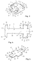
- Fig. 6
- ein erstes Ausführungsbeispiel der Anordnung gemäß den Fig. 2 und 5; und
- Fig. 7
- ein zweites Ausführungsbeispiel der Anordnung gemäß der Fig. 2.
- Fig. 1
- a schematic perspective view of an arrangement for fixing a contact spring in the region of a receiving opening in a sheet metal wall, the contact spring being shown separately from the receiving opening;
- Fig. 2
- a schematic perspective view of Figure 1, wherein the contact spring is pressed into the receiving opening.
- Fig. 3
- a schematic perspective view of the contact spring attached to a spring strip;
- Fig. 4
- a plan view of the arrangement of Figure 3 in its bent state.
- Fig. 5
- a schematic perspective view of a contact plate;
- Fig. 6
- a first embodiment of the arrangement of Figures 2 and 5. and
- Fig. 7
- a second embodiment of the arrangement of FIG. 2nd
In den Fig. 1 und 2 ist eine Anordnung 1 zum Fixieren eines mechanischen und/oder elektrischen Verbindungselementes 2 im Bereich einer Aufnahmeöffnung 3 an einer Blechwand 4 gezeigt. Das Verbindungselement 2 ist dabei als Kontaktfeder 5 ausgebildet. Die Aufnahmeöffnung 3 ist durch einen Quersteg 6 in zwei Öffnungsabschnitte 10, 11 geteilt, die in den Fig. 1, 2 und 6, 7 rechteckig ausgebildet sind.1 and 2 show an
Die Kontaktfeder 5 wird von einem länglichen Federstreifen 12 getragen, der aus zwei einander gegenüber liegenden Enden 13, 14 und einem die Enden verbindenden mittleren Abschnitt 15 besteht. Die Enden 13, 14 sind bei einem Aufliegen des mittleren Abschnitts 15 auf dem Quersteg 6 jeweils in einen der Öffnungsabschnitte 10, 11 eindrückbar, so daß die Länge des Federstreifens 12 die Breite des Querstegs 6 übersteigt und die Breite der Enden 13, 14 geringfügig größer ist als die Breite des jeweiligen Öffnungsabschnitts 10, 11. Beim Eindrükken der Enden 13, 14 in den jeweiligen Öffnungsabschnitt 10, 11 liegt der mittlere Abschnitt 15 des Federstreifens 12 zumindest teilweise auf dem Quersteg 6, insbesondere auf dessen Längskanten 16, 17 auf. Bei einer besonders bevorzugten Ausführungsform ist der mittlere Abschnitt 15 geringfügig länger als die zwischen den Längskanten 16, 17 sich erstreckende Breite des Querstegs 6.The
Wie in den Fig. 1 bis 3 angedeutet, sind die Enden 13, 14 in Längsrichtung des Federstreifens 12 unter Bildung einer entgegen der Eindrückrichtung sich öffnenden V-Form 20 mittig bei 21 angeknickt. Die Längsenden 22, 23 (siehe Fig. 4) des Federstreifens 12 haben jeweils eine mittige Einkerbung 24, 25, die etwa halbkreisförmig ausgebildet ist. Zwischen den Enden 13, 14 und dem mittleren Abschnitt 15 sind in Querrichtung des Federstreifens 12 verlaufende, etwa halbkreisförmige Einschnitte 26 bis 29 vorgesehen, so daß die Breite der Enden 13, 14 in diesem Bereich geringer ist als zwischen den Längsseiten 32 bis 35 der Enden 13, 14 (siehe Fig. 4). Die Einschnitte 26 bis 29 begünstigen ein Eindrücken der Enden 13, 14 in den jeweiligen Öffnungsabschnitt 10, 11, da sie sowohl die Bildung der V-Form als auch ein Abknicken der gesamten Enden 13, 14 in Eindrückrichtung (siehe Fig. 2) unterstützen. Fig. 2 verdeutlicht nämlich, daß die die jeweilige Einkerbung 24, 25 tragende Querseite 36, 37 der Enden in Eindrückrichtung tiefer in dem jeweiligen Öffnungsabschnitt 10, 11 angeordnet ist als das den Einschnitten 26 bis 29 nahe Ende der Längsseiten 32 bis 35.As indicated in FIGS. 1 to 3, the ends 13, 14 in the longitudinal direction of the
Wie in Fig. 4 gestrichelt angedeutet, kann die Breite der Enden 13, 14 in Richtung zum jeweiligen Längsende 22, 23 des Federstreifens 12 hin zunehmen, so daß insgesamt jeweils ein schwalbenschwanzartig geformtes Ende entsteht. Diese Ausführungsform begünstigt ein Erhöhen der den Federstreifen in dem jeweiligen Öffnungsabschnitt haltenden Querspannung zum Längsende des Federstreifens hin und verhindert dadurch ein Herausgleiten des Federstreifens aus der Aufnahmeöffnung insbesondere im Bereich der Längsenden des Federstreifens.As indicated by dashed lines in Fig. 4, the width of the
In den Fig. 1 bis 4 ist die Anordnung 1 zum Fixieren der elektrischen Kontaktfeder 5 dargestellt. Diese ist einstückig mit dem mittleren Abschnitt 15 des Federstreifens 12 verbunden und als ein sich quer zur Längsrichtung des Federstreifens erstreckender Federarm 40 ausgebildet. Das eine Ende 41 ist dabei einstückig mit dem mittleren Abschnitt 15 verbunden, wohingegen das andere Ende 42 als freies Ende und etwa T-förmig ausgebildet ist. Der sich parallel zur Längsrichtung des Federstreifens 12 erstreckende Abschnitt 43 des T-förmigen freien Endes 42 hat an seinen Enden vollständig oder, wie in Fig. 4 gestrichelt dargestellt, teilweise schräg verlaufende Kanten 44, 45.1 to 4, the
Die Kontaktfeder 5 ist mit ihrem einen Ende 41 etwa halbkreisförmig von dem mittleren Abschnitt 15 des Federstreifens 12 abgebogen. Der Federarm 40 ist gemäß den Fig. 1 bis 3 konvex, d.h. in den Figuren nach oben, durchgebogen und hat eine Außenfläche 46; die als glatte Kontaktfläche ausgebildet ist. Das freie Ende 42 des Federarms 40 ist gemäß den Fig. 1 bis 3 etwa vertikal so in Richtung auf den Federstreifen abgebogen, daß zumindest der Abschnitt 43 des Federarms 40 unterhalb des Federstreifens 12 angeordnet und die Enden des Abschnittes 43 mit ihren schräg verlaufenden Kanten 44, zum Federstreifen hin abgewinkelt sind. In der Einbaustellung gemäß Fig. 2 ist die Blechwand 4 zwischen dem mittleren Abschnitt 15 und dem Abschnitt 43 des Federarms 40 angeordnet, wobei ersterer auf der Blechwand aufliegt und letzterer unterhalb der Blechwand und diese hintergreifend angeordnet ist.The
Der Federarm kann in einer anderen Ausführungsform an seinem Ende 41 zunächst scharfkantig abgeknickt und im weiteren Verlauf zwischen dem Ende 41 und dem freien Ende 42 nach außen, d.h. in den Fig. 1 bis 3 nach oben, hin angewinkelt sein und in diesem Bereich geradlinig, d.h. nicht konvex gebogen, ausgebildet sein.In another embodiment, the spring arm can first be kinked at its
In Fig. 5 ist eine weitere Ausführungsform der Anordnung 1 gezeigt, bei welcher das Verbindungselement 2 als elektrische Kontaktplatte 47 ausgebildet ist, die im wesentlichen durch den die Enden 13, 14 verbindenden mittleren Abschnitt 15 des Federstreifens 12 gebildet ist. Die Anordnung gemäß Fig. 5 kann vollständig derjenigen der Fig. 4 entsprechen, wobei lediglich der in der linken Figurenhälfte der Fig. 4 sich erstreckende Federarm 40 weggelassen ist. Die Teile der Anordnung gemäß Fig. 5 haben deshalb, soweit sie denjenigen in den anderen Figuren entsprechen, dasselbe Bezugszeichen. Gemäß den Fig. 1 bis 5 hat der mittlere Abschnitt 15 des Federstreifens 12 eine wesentlich größere Breite als seine Enden 13, 14, so daß ach dieser auf der die Aufnahmeöffnung 3 begrenzenden Blechwand 4 abstützen kann (vergleiche Fig. 2).5 shows a further embodiment of the
Wie in den Fig. 6 und 7 dargestellt, dient die zuvor beschriebene Anordnung dazu, einen Masseschluß zwischen Gehäuseteilen 50, 51 und dadurch einen guten elektrischen Kontakt sicherzustellen. In den Fig. 6 und 7 ist jeweils eine obere Ecke der Gehäuseteile 50, 51 gezeigt, die jeweils einen horizontalen Abschnitt 52, 53 und einen damit verbundenen vertikalen Abschnitt 54, 55 haben. In den einander gegenüberliegenden Seiten der Abschnitte 52 bis 55 sind gemäß Fig. 6 ebenfalls zueinander ausgerichtete Aufnahmeöffnungen 3 vorgesehen, in die im Falle des Gehäuseteils 50 ein als Kontaktplatte 47 ausgebildeter Federstreifen 12 und im Falle des Gehäuseteils 51 ein eine Kontaktfeder 5 tragender Federstreifen 12 eingedrückt ist. Die beiden Gehäuseteile 50, 51 sind beispielsweise über ein nicht gezeigtes Scharniergelenk miteinander verbunden.As shown in FIGS. 6 and 7, the arrangement described above serves to ensure a ground connection between
Die Ausführungsform gemäß Fig. 7 ist in bezug auf das Gehäuseteil 51 identisch zu der in Fig. 6 dargestellten Ausführungsform. Lediglich das Gehäuseteil 50 ist insofern anders ausgebildet, als auf die zum Gehäuseteil 51 weisenden Abschnitte 52, 54 rechteckige, längliche Kontaktflächen 56, 57 aufgebracht sind, die mit den Kontaktfedern 5 und den Federstreifen 12 des Gehäuseteils 51 zusammenwirken. Bei einem Verschwenken beispielsweise des rechten Gehäuseteils 51 um das nicht gezeigte Scharniergelenk liegen die Gehäuseteile 50, 51 schließlich aneinander an, so daß die jeweilige Kontaktfläche des Federarms 40 der Kontaktfeder 5 mit der Kontaktfläche der Kontaktplatte 47 (siehe Fig. 6) oder mit den Kontaktflächen 56, 57 zusammenwirken kann. Da der Federarm 40 jeder Kontaktfeder 5 von dem jeweiligen Federstreifen 12 absteht, ist ein elektrischer Kontakt und eine elektrische Schirmung auch dann gewährleistet, wenn zwischen den beiden Gehäuseteilen ein Spalt angeordnet ist. Bei einem Masseschluß zwischen den Gehäuseteilen durch ein gegenseitiges Beaufschlagen der gegenüberliegenden Kontaktflächen sind die Federarme 40 in Richtung auf den mittleren Abschnitt des Federstreifens 12 so verschwenkt, daß sich jeder Abschnitt 43 in den Fig. 6 und 7 nach rechts von der Rückseite 58 der Blechwand 4 abhebt.The embodiment according to FIG. 7 is identical with respect to the
Es ist aber auch möglich, als Verbindungselement nicht eine Kontaktfeder sondern irgendein anderes Element vorzusehen, das möglichst nachgiebig mit dem Federstreifen verbunden ist und von diesem absteht. Ein solches Element kann auch ein an dem Federstreifen befestigter Stift oder eine Schraube sein. Wichtig ist nur, daß der maximale Abstand zwischen dem Verbindungselement und der Blechwand wenigstens dem (Abstand der einander gegenüberliegend angeordneten Kontaktflächen im zusammengebauten Zustand eines elektrischen oder elektronischen Gerätes entspricht. Kontaktfeder oder Kontaktplatte sind dabei so ausgebildet, daß die Relativbewegung der Kontaktfeder in bezug auf den Federstreifen nicht zum Überbiegen der Feder führen kann. Die Oberfläche der Kontaktfeder kann zur sicheren Kontaktgabe beliebig galvanisch veredelt sein. Die Kontaktfeder sollte ferner hoch elastisch sein und mit einer weichen Federkennlinie große Gehäusespalttoleranzen aufnehmen können. Wie insbesondere in den Fig. 6 und 7 gezeigt, sind bei einer bevorzugten Ausführungsform der Anordnung sämtliche Aufnahmeöffnungen 3 identisch ausgebildet, so daß in diese sowohl ein die Kontaktplatte bildender Federstreifen als auch ein die Kontaktfeder tragender Federstreifen eingedrückt werden kann. Die Blechstärken der Verbindungselemente und/oder des Federstreifens können sehr unterschiedlich sein und sind nicht auf dünne Federstahlbleche beschränkt. Außerdem ist es möglich, die Anordnung zum Fixieren eines mechanischen und/oder elektrischen Verbindungselements auch als Haltevorrichtung auszubilden, bei der ein Gehäuseteil mittels der Anordnung z.B. über am Federarm angebrachte Scharniergelenke an dem anderen Gehäuseteil schwenkbar gehalten sein kann.However, it is also possible to provide, as a connecting element, not a contact spring, but any other element which is connected to the spring strip as flexibly as possible and protrudes therefrom. Such an element can also be a pin or a screw attached to the spring strip. It is only important that the maximum distance between the connecting element and the sheet metal wall corresponds at least to the (distance of the oppositely arranged contact surfaces in the assembled state of an electrical or electronic device. Contact spring or contact plate are designed so that the relative movement of the contact spring with respect to the The surface of the contact spring can be galvanically refined for safe contacting. The contact spring should also be highly elastic and be able to accommodate large housing gap tolerances with a soft spring characteristic. As shown in particular in FIGS. 6 and 7, In a preferred embodiment of the arrangement, all receiving
Ein (nicht gezeigtes) Werkzeug zum Eindrücken der Enden 13, 14 des Federstreifens 12 der Fixieranordnung 1 in eine Aufnahmeöffnung 3 besteht vorzugsweise aus zwei den Federstreifen 12 in Längsrichtung zwischen sich aufnehmenden Eindrückbacken, zwischen denen eine das Durchbiegen des Federstreifens erlaubende Aussparung ausgebildet ist. Jede Eindrückbacke hat einen mittigen, nach innen gerichteten und in die jeweilige Einkerbung des Federstreifens passenden Vorsprung.A tool (not shown) for pushing in the
Nachfolgend wird das Eindrücken des die Kontaktfeder 5 tragenden Federstreifens 12 in eine Aufnahmeöffnung 3 an einer Blechwand 4 näher beschrieben.The pressing of the
Der Federstreifen mit der damit verbundenen Kontaktfeder wird derart zwischen die Eindrückbacken des Werkzeugs eingesetzt, daß der Federarm der Kontaktfeder sich in die Aussparung zwischen den Eindrückbacken erstreckt und der jeweilige Vorsprung jeder Eindrückbacke in die entsprechende Aussparung der Längsenden des Federstreifens eingreift. Demnach ist der die Kontaktfeder tragende Federstreifen so in dem Werkzeug angeordnet, daß sich dieser nach außen und die Kontaktfeder zum Werkzeug weisend erstreckt.The spring strip with the associated contact spring is inserted between the press-in jaws of the tool in such a way that the spring arm of the contact spring extends into the recess between the press-in jaws and the respective projection of each press-in jaw engages in the corresponding recess in the longitudinal ends of the spring strip. Accordingly, the spring strip carrying the contact spring is arranged in the tool in such a way that it extends outwards and the contact spring extends toward the tool.
Nunmehr wird das Werkzeug mit dem die Kontaktfeder tragenden Federstreifen in Richtung auf die Aufnahmeöffnung 3 z. B. der Fig. 1 geführt. Der Eindrückvorgang geschieht derart, daß zunächst der Federstreifen 12 auf die Aufnahmeöffnung 3 aufgelegt wird, wobei die Federenden 13, 14 auf den Öffnungsabschnitten 10, 11 und der mittlere Abschnitt 15 auf dem Quersteg 6 aufliegen. Bei einem Weiterbewegen des Werkzeugs in der Eindrückrichtung wird das jeweilige Ende 13, 14 in den entsprechenden Öffnungsabschnitt 10, 11 eingedrückt, wobei sich der Federstreifen in Querrichtung durchbiegt und jedes Ende 13, 14 zusätzlich in Längsrichtung, d.h. längs der mittigen Knickstelle so zusammengedrückt wird, daß sich der entgegen der Eindrückrichtung sich öffnende Winkel 60 der V-Form geringfügig verkleinert (vergleiche Fig. 2). Beim Durchbiegen des Federstreifens 12 in Querrichtung liegt dieser vornehmlich auf den Längskanten 16, 17 des Querstegs 6 auf. Außerdem gleitet der Abschnitt 43 des Federarms 40 mit seinen schräg verlaufenden Kanten 44, 45 auf der Blechwand 4 in Fig. 2 horizontal nach rechts, bis die Innenkanten 61 (siehe Fig. 3) entlang der Seitenwand 62 der Blechwand 4 vertikal nach unten gleiten können und schließlich die Blechwand 4 gemäß der Darstellung in Fig. 2 hintergreifen. Diese Figur zeigt ferner, daß die Längsenden des Federstreifens 12 tiefer in den jeweiligen Öffnungsabschnitt eingedrückt sind als die Längsseiten 32 bis 35 nahe den Einschnitten 26 bis 29. Eine solche Anordnung der Enden kann dadurch erreicht werden, daß das Werkzeug im Bereich zwischen den Vorsprüngen der Eindrückbacken und der Aussparung konisch ausgebildet ist.Now the tool with the spring strip carrying the contact spring in the direction of the receiving opening 3 z. B. Fig. 1 performed. The pressing-in process takes place in such a way that the
Kurz nach einem Abziehen des Werkzeugs nach dem Eindrückvorgang schneidet sich das jeweilige Ende 13, 14 des Federstreifens 12 infolge der zuvor beschriebenen Durchbiegung des Federstreifens in Längs- und Querrichtung geringfügig in Pfeilrichtung 63, 64 in den jeweiligen Öffnungsabschnitt ein und verspreizt sich darin in Querrichtung, d.h. längs der Pfeile 65 bis 68. Demnach führt jedes Ende 13, 14 des Federstreifens kurz nach dem Abziehen des Werkzeugs eine Setzbewegung in Längs- und Querrichtung aus. Dadurch drücken sich die scharfkantigen Längsseiten 32 bis 35 der Enden fest in den jeweiligen Öffnungsabschnitt ein, wodurch eine gegebenenfalls vorhandene Lackschicht aufgerissen und ein unmittelbarer Kontakt zwischen Metallteilen entsteht.Shortly after the tool has been removed after the pressing-in process, the
Ein lediglich die Kontaktplatte 47 bildender Federstreifen wird in der gleichen Weise in die Aufnahmeöffnung 3 eingedrückt.A spring strip forming only the
Claims (10)
- Arrangement for fixing a mechanical and/or electrical connecting element (2), in particular a contact spring, in the region of an accommodating opening (3) on a sheet metal wall (4), having a transverse web (6) which divides the accommodating opening (3) into two opening sections (10, 11), and having a spring strip (12) which supports the connecting element (2) and is longer than the width of the transverse web (6) and whose ends (13, 14) can respectively be pressed, when it is at least partially resting on the transverse web (6), in one of the opening sections (10, 11), characterized in that the ends (13, 14) respectively have a width which is slightly greater than the width of the respective opening section (10, 11), with the result that each end (13, 14) can be firmly clamped in the corresponding opening section (10, 11), and in that the spring strip (12) is shorter in the longitudinal direction than the length of the opening (3).
- Arrangement according to Claim 1, characterized in that, in the longitudinal direction of the spring strip (12), the ends (13, 14) are incipiently bent in the middle with the formation of a V-shape (20) opening against the pressing-in direction.
- Arrangement according to Claim 1 or 2, characterized in that the width of the ends (13, 14) increases in the direction towards the respective longitudinal end (22, 23) of the spring strip (12).
- Arrangement according to one of Claims 1 to 3, characterized in that the longitudinal ends (22, 23) of the spring strip (12) in each case have a notch (24, 25) in the middle.
- Arrangement according to one of the preceding claims for fixing an electrical contact spring, characterized in that the contact spring (5) is connected in one piece to the middle section (15), connecting the ends (13, 14), of the spring strip (12).
- Arrangement according to Claim 5, characterized in that the contact spring (5) is a spring arm (40) which extends transverse to the longitudinal direction of the spring strip (12) and whose outer surface (46) is constructed as a contact surface.
- Arrangement according to one of Claims 1 to 4, for fixing an electrical contact plate forming the connecting element, characterized in that the contact plate (47) is formed by the middle section (15), connecting the ends (13, 14), of the spring strip (12).
- Arrangement according to Claim 5 or 7, characterized in that the middle section (15) of the spring strip (12) is substantially wider than its ends (13, 14).
- Tool in combination with the spring strip (12) of a fixing arrangement according to one of the preceding claims for pressing the ends of the spring strip (12) into an accommodating opening, characterized by two press-in jaws which accommodate the spring strip (12) between them in the longitudinal direction, and between which a recess is formed which permits the spring strip (12) to deflect.
- Tool according to Claim 9 for pressing in the ends of the spring strip (12) of a fixing arrangement according to one of Claims 4 to 8, characterized in that each press-in jaw has a middle, inwardly directed projection which fits into the respective notch (24, 25) of the spring strip (12).
Applications Claiming Priority (2)
| Application Number | Priority Date | Filing Date | Title |
|---|---|---|---|
| DE3935717A DE3935717C1 (en) | 1989-10-26 | 1989-10-26 | |
| DE3935717 | 1989-10-26 |
Publications (3)
| Publication Number | Publication Date |
|---|---|
| EP0424806A2 EP0424806A2 (en) | 1991-05-02 |
| EP0424806A3 EP0424806A3 (en) | 1992-01-08 |
| EP0424806B1 true EP0424806B1 (en) | 1994-02-02 |
Family
ID=6392292
Family Applications (1)
| Application Number | Title | Priority Date | Filing Date |
|---|---|---|---|
| EP90120001A Expired - Lifetime EP0424806B1 (en) | 1989-10-26 | 1990-10-18 | Device for fixing a mechanical and/or electrical connection element, especially a contact spring |
Country Status (3)
| Country | Link |
|---|---|
| EP (1) | EP0424806B1 (en) |
| DE (2) | DE3935717C1 (en) |
| ES (1) | ES2048930T3 (en) |
Families Citing this family (7)
| Publication number | Priority date | Publication date | Assignee | Title |
|---|---|---|---|---|
| DE4217436C1 (en) * | 1992-05-26 | 1993-09-09 | Siemens Nixdorf Informationssysteme Ag, 33106 Paderborn, De | Individual contact spring for HF screening of electronic appts - has spring contact cap attached by two perpendicular tongues to fixing cage located in appts. panel opening |
| FI97938C (en) * | 1993-06-03 | 1997-03-10 | Nokia Telecommunications Oy | Sealing device for attenuation of interference radiation in an electric field |
| SE503467C2 (en) * | 1994-12-14 | 1996-06-17 | Ericsson Telefon Ab L M | Grounding and shielding device |
| DE19601615C1 (en) * | 1996-01-18 | 1997-04-30 | Loh Kg Rittal Werk | Electrical connection device for switch cabinet mounting plate |
| DE19601614C1 (en) * | 1996-01-18 | 1997-04-17 | Loh Kg Rittal Werk | Clip for ensuring continuity between electrical enclosure and door |
| ITRM20050202A1 (en) * | 2005-04-29 | 2006-10-30 | Bticino Spa | ELECTRICAL CONNECTION DEVICE BETWEEN A PANEL AND AN ELECTRIC PANEL. |
| DE102018009030A1 (en) * | 2018-11-16 | 2020-05-20 | Zf Active Safety Gmbh | Bearing arrangement |
Family Cites Families (3)
| Publication number | Priority date | Publication date | Assignee | Title |
|---|---|---|---|---|
| DE8310731U1 (en) * | 1983-04-12 | 1983-09-15 | Nixdorf Computer Ag, 4790 Paderborn | Contact arrangement for making electrical contact between adjacent housing parts |
| DE3328395A1 (en) * | 1983-08-05 | 1985-02-14 | Siemens AG, 1000 Berlin und 8000 München | HIGH-FREQUENCY DENSITY SHIELDING OF AREA PARTS |
| US4803306A (en) * | 1987-06-03 | 1989-02-07 | Computervision Corporation | Electromagnetic shielding clip |
-
1989
- 1989-10-26 DE DE3935717A patent/DE3935717C1/de not_active Expired - Fee Related
-
1990
- 1990-10-18 EP EP90120001A patent/EP0424806B1/en not_active Expired - Lifetime
- 1990-10-18 DE DE90120001T patent/DE59004503D1/en not_active Expired - Fee Related
- 1990-10-18 ES ES90120001T patent/ES2048930T3/en not_active Expired - Lifetime
Also Published As
| Publication number | Publication date |
|---|---|
| DE3935717C1 (en) | 1991-02-07 |
| EP0424806A3 (en) | 1992-01-08 |
| EP0424806A2 (en) | 1991-05-02 |
| DE59004503D1 (en) | 1994-03-17 |
| ES2048930T3 (en) | 1994-04-01 |
Similar Documents
| Publication | Publication Date | Title |
|---|---|---|
| EP3507866B1 (en) | Conductor connection clamp | |
| DE102015211002B4 (en) | Connector with a connector housing and a connector terminal | |
| DE2941029A1 (en) | ELECTRICAL CONNECTING PART PROVIDED FOR PRESS-IN CONNECTING, METHOD FOR CONNECTING A CONNECTING PART TO AN ELECTRICAL LADDER AND CONNECTOR WITH A MULTIPLE RANGE OF ELECTRICAL CONNECTING PARTS | |
| EP2475057B2 (en) | Cable holding device | |
| EP2551962A1 (en) | Electrical connection device | |
| DE4111054C2 (en) | ||
| DE10253858B4 (en) | Terminal clamping element and thus formed terminal | |
| EP2756238B1 (en) | Device for fastening a mounting rail on a roof hook | |
| DE3628211A1 (en) | COMPONENT HOLDER | |
| EP1559176A1 (en) | Clamping connector for flexible ribbon cables | |
| EP3843221A1 (en) | Supporting frame for a connector | |
| DE10100182B4 (en) | Spring for attaching a terminal block to a rail | |
| EP0424806B1 (en) | Device for fixing a mechanical and/or electrical connection element, especially a contact spring | |
| DE3411914C1 (en) | Device for connecting wall elements, for printing blocks in printing devices | |
| DE3818497C5 (en) | Terminal block for a cable termination unit | |
| DE2239769A1 (en) | CONNECTOR FOR ELECTRIC CABLE | |
| DE602005003380T2 (en) | Method for mounting a reinforcing part on the front panel of a refrigerator or freezer | |
| DE3643087A1 (en) | QUICK COUPLING CLAMP FOR THE TERMINAL POLE OF AN ELECTRICAL DEVICE | |
| EP1523069A1 (en) | Contact spring for an antenna amplifier | |
| DE102011015118A1 (en) | Safety terminal for PV modules and method for securing PV modules in an insertion system | |
| EP1045475A2 (en) | Screwless terminal or joining clamp for electrical conductor | |
| DE69821547T2 (en) | Method of making electrical connectors and connectors | |
| WO1998012436A1 (en) | Lock-in device for a straight moving building component | |
| EP1243078B1 (en) | Electrical device comprising a housing | |
| DE102019131804A1 (en) | Parking frame, connector and electronic device |
Legal Events
| Date | Code | Title | Description |
|---|---|---|---|
| PUAI | Public reference made under article 153(3) epc to a published international application that has entered the european phase |
Free format text: ORIGINAL CODE: 0009012 |
|
| AK | Designated contracting states |
Kind code of ref document: A2 Designated state(s): AT BE CH DE DK ES FR GB GR IT LI LU NL SE |
|
| RBV | Designated contracting states (corrected) |
Designated state(s): DE ES FR GB IT NL SE |
|
| PUAL | Search report despatched |
Free format text: ORIGINAL CODE: 0009013 |
|
| AK | Designated contracting states |
Kind code of ref document: A3 Designated state(s): AT BE CH DE DK ES FR GB GR IT LI LU NL SE |
|
| 17P | Request for examination filed |
Effective date: 19920702 |
|
| 17Q | First examination report despatched |
Effective date: 19920916 |
|
| GRAA | (expected) grant |
Free format text: ORIGINAL CODE: 0009210 |
|
| AK | Designated contracting states |
Kind code of ref document: B1 Designated state(s): DE ES FR GB IT NL SE |
|
| REF | Corresponds to: |
Ref document number: 59004503 Country of ref document: DE Date of ref document: 19940317 |
|
| REG | Reference to a national code |
Ref country code: ES Ref legal event code: FG2A Ref document number: 2048930 Country of ref document: ES Kind code of ref document: T3 |
|
| ITF | It: translation for a ep patent filed |
Owner name: STUDIO JAUMANN |
|
| GBT | Gb: translation of ep patent filed (gb section 77(6)(a)/1977) |
Effective date: 19940412 |
|
| ET | Fr: translation filed | ||
| PGFP | Annual fee paid to national office [announced via postgrant information from national office to epo] |
Ref country code: SE Payment date: 19940912 Year of fee payment: 5 |
|
| PGFP | Annual fee paid to national office [announced via postgrant information from national office to epo] |
Ref country code: GB Payment date: 19940916 Year of fee payment: 5 |
|
| PGFP | Annual fee paid to national office [announced via postgrant information from national office to epo] |
Ref country code: ES Payment date: 19941006 Year of fee payment: 5 |
|
| PGFP | Annual fee paid to national office [announced via postgrant information from national office to epo] |
Ref country code: FR Payment date: 19941024 Year of fee payment: 5 |
|
| PGFP | Annual fee paid to national office [announced via postgrant information from national office to epo] |
Ref country code: NL Payment date: 19941031 Year of fee payment: 5 |
|
| PLBE | No opposition filed within time limit |
Free format text: ORIGINAL CODE: 0009261 |
|
| STAA | Information on the status of an ep patent application or granted ep patent |
Free format text: STATUS: NO OPPOSITION FILED WITHIN TIME LIMIT |
|
| PGFP | Annual fee paid to national office [announced via postgrant information from national office to epo] |
Ref country code: DE Payment date: 19941216 Year of fee payment: 5 |
|
| 26N | No opposition filed | ||
| EAL | Se: european patent in force in sweden |
Ref document number: 90120001.4 |
|
| PG25 | Lapsed in a contracting state [announced via postgrant information from national office to epo] |
Ref country code: GB Effective date: 19951018 |
|
| PG25 | Lapsed in a contracting state [announced via postgrant information from national office to epo] |
Ref country code: SE Effective date: 19951019 Ref country code: ES Free format text: LAPSE BECAUSE OF THE APPLICANT RENOUNCES Effective date: 19951019 |
|
| PG25 | Lapsed in a contracting state [announced via postgrant information from national office to epo] |
Ref country code: NL Effective date: 19960501 |
|
| GBPC | Gb: european patent ceased through non-payment of renewal fee |
Effective date: 19951018 |
|
| PG25 | Lapsed in a contracting state [announced via postgrant information from national office to epo] |
Ref country code: FR Effective date: 19960628 |
|
| EUG | Se: european patent has lapsed |
Ref document number: 90120001.4 |
|
| NLV4 | Nl: lapsed or anulled due to non-payment of the annual fee |
Effective date: 19960501 |
|
| PG25 | Lapsed in a contracting state [announced via postgrant information from national office to epo] |
Ref country code: DE Effective date: 19960801 |
|
| REG | Reference to a national code |
Ref country code: FR Ref legal event code: ST |
|
| REG | Reference to a national code |
Ref country code: ES Ref legal event code: FD2A Effective date: 19991007 |
|
| PG25 | Lapsed in a contracting state [announced via postgrant information from national office to epo] |
Ref country code: IT Free format text: LAPSE BECAUSE OF NON-PAYMENT OF DUE FEES;WARNING: LAPSES OF ITALIAN PATENTS WITH EFFECTIVE DATE BEFORE 2007 MAY HAVE OCCURRED AT ANY TIME BEFORE 2007. THE CORRECT EFFECTIVE DATE MAY BE DIFFERENT FROM THE ONE RECORDED. Effective date: 20051018 |