EP3843221A1 - Supporting frame for a connector - Google Patents
Supporting frame for a connector Download PDFInfo
- Publication number
- EP3843221A1 EP3843221A1 EP20212986.2A EP20212986A EP3843221A1 EP 3843221 A1 EP3843221 A1 EP 3843221A1 EP 20212986 A EP20212986 A EP 20212986A EP 3843221 A1 EP3843221 A1 EP 3843221A1
- Authority
- EP
- European Patent Office
- Prior art keywords
- holding frame
- connection
- contact
- tabs
- holding
- Prior art date
- Legal status (The legal status is an assumption and is not a legal conclusion. Google has not performed a legal analysis and makes no representation as to the accuracy of the status listed.)
- Pending
Links
- 239000004020 conductor Substances 0.000 claims abstract description 34
- 230000001681 protective effect Effects 0.000 claims abstract description 17
- 238000003780 insertion Methods 0.000 claims description 20
- 230000037431 insertion Effects 0.000 claims description 20
- 229910052751 metal Inorganic materials 0.000 claims description 7
- 239000002184 metal Substances 0.000 claims description 7
- 239000000463 material Substances 0.000 claims description 6
- 229910000831 Steel Inorganic materials 0.000 claims description 4
- HCHKCACWOHOZIP-UHFFFAOYSA-N Zinc Chemical compound [Zn] HCHKCACWOHOZIP-UHFFFAOYSA-N 0.000 claims description 4
- 229910052782 aluminium Inorganic materials 0.000 claims description 4
- XAGFODPZIPBFFR-UHFFFAOYSA-N aluminium Chemical compound [Al] XAGFODPZIPBFFR-UHFFFAOYSA-N 0.000 claims description 4
- 239000010959 steel Substances 0.000 claims description 4
- 239000011701 zinc Substances 0.000 claims description 4
- 229910052725 zinc Inorganic materials 0.000 claims description 4
- RYGMFSIKBFXOCR-UHFFFAOYSA-N Copper Chemical compound [Cu] RYGMFSIKBFXOCR-UHFFFAOYSA-N 0.000 claims description 3
- 229910052802 copper Inorganic materials 0.000 claims description 3
- 239000010949 copper Substances 0.000 claims description 3
- 238000004512 die casting Methods 0.000 claims description 3
- 238000000034 method Methods 0.000 claims description 3
- 239000011810 insulating material Substances 0.000 claims description 2
- 230000015572 biosynthetic process Effects 0.000 description 4
- 238000005520 cutting process Methods 0.000 description 2
- 238000004519 manufacturing process Methods 0.000 description 2
- 238000005476 soldering Methods 0.000 description 2
- 238000003466 welding Methods 0.000 description 2
- 238000005452 bending Methods 0.000 description 1
- 238000009434 installation Methods 0.000 description 1
- 230000013011 mating Effects 0.000 description 1
- 238000004080 punching Methods 0.000 description 1
- 238000004904 shortening Methods 0.000 description 1
Images

Classifications
-
- H—ELECTRICITY
- H01—ELECTRIC ELEMENTS
- H01R—ELECTRICALLY-CONDUCTIVE CONNECTIONS; STRUCTURAL ASSOCIATIONS OF A PLURALITY OF MUTUALLY-INSULATED ELECTRICAL CONNECTING ELEMENTS; COUPLING DEVICES; CURRENT COLLECTORS
- H01R13/00—Details of coupling devices of the kinds covered by groups H01R12/70 or H01R24/00 - H01R33/00
- H01R13/46—Bases; Cases
- H01R13/516—Means for holding or embracing insulating body, e.g. casing, hoods
- H01R13/518—Means for holding or embracing insulating body, e.g. casing, hoods for holding or embracing several coupling parts, e.g. frames
-
- H—ELECTRICITY
- H01—ELECTRIC ELEMENTS
- H01R—ELECTRICALLY-CONDUCTIVE CONNECTIONS; STRUCTURAL ASSOCIATIONS OF A PLURALITY OF MUTUALLY-INSULATED ELECTRICAL CONNECTING ELEMENTS; COUPLING DEVICES; CURRENT COLLECTORS
- H01R13/00—Details of coupling devices of the kinds covered by groups H01R12/70 or H01R24/00 - H01R33/00
- H01R13/40—Securing contact members in or to a base or case; Insulating of contact members
- H01R13/42—Securing in a demountable manner
- H01R13/426—Securing by a separate resilient retaining piece supported by base or case, e.g. collar or metal contact-retention clip
-
- H—ELECTRICITY
- H01—ELECTRIC ELEMENTS
- H01R—ELECTRICALLY-CONDUCTIVE CONNECTIONS; STRUCTURAL ASSOCIATIONS OF A PLURALITY OF MUTUALLY-INSULATED ELECTRICAL CONNECTING ELEMENTS; COUPLING DEVICES; CURRENT COLLECTORS
- H01R13/00—Details of coupling devices of the kinds covered by groups H01R12/70 or H01R24/00 - H01R33/00
- H01R13/40—Securing contact members in or to a base or case; Insulating of contact members
- H01R13/42—Securing in a demountable manner
- H01R13/436—Securing a plurality of contact members by one locking piece or operation
-
- H—ELECTRICITY
- H01—ELECTRIC ELEMENTS
- H01R—ELECTRICALLY-CONDUCTIVE CONNECTIONS; STRUCTURAL ASSOCIATIONS OF A PLURALITY OF MUTUALLY-INSULATED ELECTRICAL CONNECTING ELEMENTS; COUPLING DEVICES; CURRENT COLLECTORS
- H01R4/00—Electrically-conductive connections between two or more conductive members in direct contact, i.e. touching one another; Means for effecting or maintaining such contact; Electrically-conductive connections having two or more spaced connecting locations for conductors and using contact members penetrating insulation
- H01R4/28—Clamped connections, spring connections
- H01R4/48—Clamped connections, spring connections utilising a spring, clip, or other resilient member
- H01R4/4809—Clamped connections, spring connections utilising a spring, clip, or other resilient member using a leaf spring to bias the conductor toward the busbar
- H01R4/4828—Spring-activating arrangements mounted on or integrally formed with the spring housing
- H01R4/48365—Spring-activating arrangements mounted on or integrally formed with the spring housing with integral release means
-
- H—ELECTRICITY
- H01—ELECTRIC ELEMENTS
- H01R—ELECTRICALLY-CONDUCTIVE CONNECTIONS; STRUCTURAL ASSOCIATIONS OF A PLURALITY OF MUTUALLY-INSULATED ELECTRICAL CONNECTING ELEMENTS; COUPLING DEVICES; CURRENT COLLECTORS
- H01R4/00—Electrically-conductive connections between two or more conductive members in direct contact, i.e. touching one another; Means for effecting or maintaining such contact; Electrically-conductive connections having two or more spaced connecting locations for conductors and using contact members penetrating insulation
- H01R4/58—Electrically-conductive connections between two or more conductive members in direct contact, i.e. touching one another; Means for effecting or maintaining such contact; Electrically-conductive connections having two or more spaced connecting locations for conductors and using contact members penetrating insulation characterised by the form or material of the contacting members
- H01R4/64—Connections between or with conductive parts having primarily a non-electric function, e.g. frame, casing, rail
- H01R4/646—Connections between or with conductive parts having primarily a non-electric function, e.g. frame, casing, rail for cables or flexible cylindrical bodies
-
- H—ELECTRICITY
- H01—ELECTRIC ELEMENTS
- H01R—ELECTRICALLY-CONDUCTIVE CONNECTIONS; STRUCTURAL ASSOCIATIONS OF A PLURALITY OF MUTUALLY-INSULATED ELECTRICAL CONNECTING ELEMENTS; COUPLING DEVICES; CURRENT COLLECTORS
- H01R13/00—Details of coupling devices of the kinds covered by groups H01R12/70 or H01R24/00 - H01R33/00
- H01R13/46—Bases; Cases
- H01R13/514—Bases; Cases composed as a modular blocks or assembly, i.e. composed of co-operating parts provided with contact members or holding contact members between them
Definitions
- the invention relates to a holding frame for a connector for receiving several contact inserts, with two opposite side parts and two opposite end parts, the two end parts being arranged perpendicular to the side parts, with at least one elastic tab being provided on each of the two side parts and with the tabs each have a latching means for fixing a latching projection of a contact insert inserted into the holding frame, at least one end part consisting at least partially of an electrically conductive material and having a PE connection.
- Such holding frames are used to accommodate a plurality of contact inserts which can be inserted into the holding frame and which consist of an insulating body with a rectangular cross section, in which different contact elements can be arranged. Because the contact inserts can be inserted individually into the holding frame, it is possible to equip a holding frame with different contact inserts, depending on the intended use.
- the holding frame with the contact inserts is thus constructed in a modular manner, so that the contact inserts are also referred to as contact insert modules or contact modules.
- the fully equipped holding frame, in which the respective contact inserts are inserted can be inserted into a housing part of a plug connector and fastened therein, the plug connector being used for fastening with a corresponding mating plug connector.
- holding frame Various types of holding frame are known from practice, which allow a modular insertion of individual contact inserts.
- holding frames that consist of two articulated frame halves, the contact inserts being inserted into corresponding recesses in the holding frame when the holding frame is open and being positively held in their position when the holding frame is closed.
- holding frames that have a fixed base frame in which the individual contact inserts are also inserted into corresponding recesses in a first step.
- a fastening bracket is fixed to the base frame in a second step.
- the mounting bracket engages over projections that are formed on the end faces of the contact inserts and engage in corresponding recesses on the upper edge of the base frame.
- a holding frame for a connector which is formed in one piece and consists of a plastic material.
- the two opposing side walls of the holding frame have a plurality of elastic wall segments separated by slots, in each of which a window-like opening is formed.
- a contact insert with its locking projections formed on the end faces can be pushed between two opposing wall segments until the two locking projections lock into the opposing window-like openings.
- the disadvantage here is that the holding frame is made entirely of plastic, so that it is not suitable for protective grounding when the holding frame is installed in a metallic connector housing.
- the DE 10 2015 103 563 A1 discloses a holding frame made of an electrically conductive material, which consists of a rigid, rectangular base frame with two side parts and two end parts, with upwardly open recesses formed on the upper edge of the side parts, which are laterally bounded by webs that extend parallel to the direction of insertion of a Extend contact insert.
- a plurality of resilient tabs separated from one another by slots are attached to the two side parts, for which purpose the lower sections of the slots are bent over by 180 ° around the lower edge of the corresponding side wall of the base frame.
- the tabs each have a holding tongue in their bent-over section, which engages in a corresponding holding opening in the side part.
- a recess is formed in each of the tabs, the tabs being arranged on the side parts in such a way that the recesses in the tabs and the recesses in the side parts are aligned with one another.
- the upper edge of the recesses is delimited in each case by a bracket section on which an inwardly protruding locking lug is formed.
- the latch protrudes into the respective recess of a side part, so that the latching projection of a contact insert inserted in the holding frame is overlapped by the latch formed on the tab.
- the lower edge of the locking projection lies on the lower edge of the recess of the side part, while the side edges of the locking projection are held by the webs laterally delimiting the recess.
- the tabs are preferably made of a resilient sheet metal, so that the tabs have corresponding resilient properties that allow the contact inserts to be inserted between two opposing tabs until the latching projections formed on the contact inserts are overlapped by the inwardly protruding latches formed on the tabs thereby be fixed in the holding frame.
- the front parts which consist of an electrically conductive material, in particular sheet metal, each have a flange section on which a PE connection is formed.
- the PE connection has a screw connection so that a protective conductor can be electrically connected to the connection contact of the PE connection with the aid of the screw connection.
- a holding frame designed in this way enables the contact inserts to be fastened in the holding frame in a simple and, at the same time, secure manner, and individual contact inserts can also be exchanged without any problems.
- the assembly is somewhat complex, especially if a protective conductor is to be connected in confined spaces.
- the present invention is therefore based on the object of providing a holding frame that is as simple as possible to manufacture and that enables the simplest possible assembly.
- the PE connection has a screwless connection device and a metallic connection contact which is electrically conductively connected to the connection device. Because the at least one PE connection in the holding frame according to the invention does not have a screw connection but a screwless connection device, the effort involved in connecting a protective conductor is reduced. This also simplifies the assembly of the holding frame, which is associated with a shortening of the assembly times for the individual holding frames.
- a screwless connection device a cutting connection can be provided, for example, in which the end of an insulated conductor be inserted between two opposing cutting edges of a metallic connection element.
- the screwless connection device is designed as a spring-loaded terminal connection which has a clamping spring and a contact piece.
- a loop-shaped tension spring can be used as the clamping spring, with the aid of which a conductor arranged in an opening in the clamping leg of the tension spring is clamped against a busbar piece.
- a leg spring is used as the clamping spring, which has a clamping leg and a retaining leg, which are connected to one another via a spring arch.
- the clamping leg of the clamping spring forms with the contact piece a clamping point for the protective conductor to be connected by the stripped end of the protective conductor being pressed by the clamping leg against the contact piece, which is electrically connected to the connection contact.
- the advantage of a spring-loaded terminal connection with a leg spring as the clamping spring is that no additional assembly step is required to connect a rigid conductor.
- the end of a rigid conductor can simply be inserted into the terminal point, since the clamping leg is deflected from the end of the rigid conductor when it is inserted. If the protective conductor to be connected is plugged into the terminal point, it is securely held by the end of the terminal leg running obliquely to the direction of insertion of the conductor, so that the conductor is prevented from being unintentionally pulled out of the terminal point.
- the design of the PE connection as a spring-loaded terminal connection can be implemented in a particularly simple manner in that the contact piece, against which the conductor to be connected is pressed by the clamping leg of the clamping spring, is designed in one piece with the front part. If the front part consists, for example, of sheet metal, in particular a steel sheet or a sheet made of a copper material, the contact piece can simply be punched free from the front part and bent. If, on the other hand, the end part is designed as a die-cast part, in particular as a zinc die-cast part or as an aluminum die-cast part, then the contact piece is preferably molded directly onto the end part in the die-casting process.
- a housing part is arranged at least on the end part that has a PE connection.
- the housing part can be attached to the front part, preferably by means of corresponding latching elements.
- the housing part which consists of an insulating material, has a conductor entry opening for inserting the protective conductor to be connected and, moreover, preferably also an actuation opening for opening the terminal point.
- a protective conductor is not only pressed against the contact piece by the clamping leg, whereby an electrically conductive connection is established between the free end of the protective conductor and the contact piece, but the protective conductor is also protected against an unwanted one by the free end of the clamping leg Prevented pulling out of the clamping point.
- the clamping leg of the clamping spring In order to deliberately release a connected conductor from the clamping point or the spring-loaded terminal connection, the clamping leg of the clamping spring must be deflected against its spring force.
- a corresponding actuating tool for example the end of a screwdriver, can be inserted through the actuating opening into the housing part, the actuating opening being arranged in relation to the clamping spring in such a way that the clamping leg is deflected against its spring force when the actuating tool is inserted and is thus lifted off the connected conductor.
- an actuating element is arranged in the actuating opening for opening the clamping point, which actuating element can be brought from a first position in which the clamping point is closed into a second position in which the clamping point is open. In the second position of the actuating element, the clamping leg of the clamping spring is deflected by the actuating element against its spring force.
- the actuation element can be, for example, a pivotably mounted actuation lever or an actuation lever arranged displaceably in the actuation opening.
- not only the contact piece for the clamping point, but also a fastening element for the clamping spring and preferably also a stop element for the clamping leg of the clamping spring is formed on the end part, which has a PE connection.
- the formation of a corresponding fastening element ensures secure positioning and holding of the clamping spring, in which case corresponding contact sections for the clamping spring can also be formed in the housing so that the clamping spring is safely and functionally supported and positioned by the end part and the housing part.
- the formation of an additional stop element on the front part has the advantage that the clamping leg of the clamping spring is thereby protected against excessive deflection, which could damage the clamping spring or impair the spring properties.
- the holding frame according to the invention can in principle have a one-piece base frame which is formed by the two side parts and the two front parts.
- a base frame is then preferably designed as a die-cast part, for example as a zinc die-cast part or an aluminum die-cast part.
- the two side parts and the two end parts are initially designed or manufactured as separate components before the two side parts are firmly connected to the two end parts, in particular welded, soldered, riveted or stamped together.
- the individual components that is to say the side parts and the front parts, are preferably made of sheet metal, for example a sheet steel or a sheet made of a copper material.
- the side parts and the front parts preferably have interlocking contours at the connection points, so that the side parts and the front parts can first be put together or plugged together before they are permanently connected to one another at the connection points by welding, soldering, riveting or stamping.
- the design of interlocking contours has the additional advantage that, in addition to a force fit or material fit, a form fit is also generated at the connection points.
- the formation of the holding frame from several separate components also has the advantage that, in this way, different holding frames can be produced in a simple manner, which are provided for receiving different numbers of contact inserts.
- a holding frame which is intended to hold six contact inserts
- only different, correspondingly longer side parts then have to be used compared to a holding frame which is intended to hold four contact inserts, while the same end faces can be used for both holding frames.
- the individual side parts can preferably be made from an endless punched strip that is punched for different lengths depending on the size of the holding frame to be manufactured.
- the tabs on the side parts each have a locking means.
- the latching means can be, for example, recesses or latching windows in the tabs.
- two holding elements are formed as latching means on the upper region of the tabs in the insertion direction E of a contact insert, the holding elements extending perpendicular to the insertion direction E in the opposite direction outward from the upper region of the tab.
- the tabs are arranged on the side parts in such a way that in each case one tab is arranged at least with its upper area between two locking projections, so that the holding elements at least partially overlap the locking projections of the contact inserts when the contact inserts are inserted into the holding frame.
- Such a holding frame then also differs from the holding frame known from the prior art in that two holding elements are formed as latching means on the individual tabs, the two holding elements interacting with two latching projections of the contact inserts.
- the individual tabs have only one latching means, so that each tab also only interacts with one latching projection of a contact insert, regardless of whether the latching means is designed as a latching window or as a latching lug.
- the two latching projections which are at least partially overlapped by the two retaining elements of a tab, can either be formed on two contact inserts, which are arranged next to one another in the retaining frame, or on a contact insert, which then has a double width.
- a latching projection formed on its end face is overlapped by at least one holding element of a bracket. If the contact insert is located between two tabs, its latching projection is overlapped by one holding element of the two tabs, that is to say by a total of two holding elements.
- the holding elements preferably have a length perpendicular to the insertion direction E of the contact inserts, which is only slightly less than the corresponding extension of a latching projection of a contact insert, so that only a small amount of space remains between two holding elements of two adjacent tabs that jointly overlap a latching projection.
- the holding elements of the tabs are preferably designed or arranged in such a way that they form an insertion bevel for a latching projection of a contact insert.
- Such an insertion bevel can be implemented, for example, in that the holding elements are arranged at a small angle to the insertion direction E or to the longitudinal extension of the tabs on the upper region of the tabs. The holding elements are thus slightly inclined with respect to the insertion direction E.
- more than one tab for example two, three, four, five or even more tabs, are provided on both side parts.
- the at least one tab is preferably designed in one piece with the respective side part, so that fastening of the tabs to the side parts is not necessary, which means that a corresponding work step can be omitted.
- the tabs are then preferably formed on the upper edge of the side parts.
- the respective side part and the tabs formed thereon are then essentially flat, which is advantageous due to the generally limited installation space for a holding frame in a housing part of a connector.
- two shoulders are formed on the tabs, each of which is located at a distance below a holding element.
- the distance between a shoulder and the opposing holding element is selected so that the latching projection of a contact insert inserted in the holding frame rests on the shoulder and thereby is at the same time partially overlapped by the holding element.
- shoulders are formed on the tabs, which serve to support the latching projections of the contact inserts, the extension of the tabs can be selected to be relatively large.
- the brackets in the holding frame are designed as separate components or in one piece with the side parts
- the brackets of one side part preferably have a different width in their upper area than the brackets of the other side part.
- the formation of, at least in the upper area, tabs of different widths on the two opposite side parts means that the distance between two adjacent tabs in the upper area on the two side parts is also different. In this way, a coding can be created for the individual slots which only enables the contact inserts to be inserted in exactly one orientation if the latching projections provided on the contact inserts also have a different width on the two end faces.
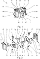
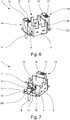
- FIGs 1 and 6th show two different design variants of a holding frame 1 according to the invention, each in a perspective view, obliquely from above, the side of the holding frame 1 from which a contact insert 2 is inserted into the holding frame 1 in the insertion direction E is referred to as "top". While the holding frame 1 according to the Fig. 1 and 6th are intended to accommodate two contact inserts each, is in Figure 3 a variant of the holding frame 1 according to Fig. 1 shown, in the three contact inserts 2 are inserted.
- the holding frame 1 has a rectangular basic shape in all embodiments and consists of two opposite side parts 3, 3 'and two also opposite end parts 4, 4', the two end parts 4, 4 'being arranged perpendicular to the side parts 3, 3' are.
- the two side parts 3, 3 ' have in the embodiment according to Figures 1 and 2 in each case only one elastic tab 5, 5 ', which are formed in one piece with the side parts 3, 3' and are arranged opposite one another.
- two tabs 5, 5 'per side part 3, 3' are provided, the tabs 5, 5 'also being formed in one piece with the side parts 3, 3' and being arranged opposite one another in pairs.
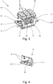
- the holding frame 1 shown also differ from that in the Figures 6 and 7 shown holding frame 1 that in the embodiments according to the Figs. 1 to 3 the side parts 3, 3 'and the front parts 4, 4' each consist of sheet metal, in particular sheet steel and are designed as separate components, while in the embodiment according to the Figures 6 and 7 the side parts 3, 3 'and the end parts 4, 4' form a one-piece base frame and are manufactured in the die-casting process as a zinc die-cast part or as an aluminum die-cast part.
- the holding frame shown in the figures has a PE connection on each of its two end parts 4, 4 ′, the PE connection being formed by a screwless connection device 7 and a connection contact 8, 9.
- One connection contact 8 is designed as a contact pin, while the other connection contact 9 is designed as a contact socket.
- the screwless connection device 7 is designed as a spring-loaded terminal connection which has a clamping spring 10 and a contact piece 11.
- the approximately V-shaped or U-shaped clamping spring 10 has a clamping leg 12 and a holding leg 13, the clamping leg 12 together with the contact piece 11 forming a clamping point for a protective conductor to be connected. In the connected state, the stripped end of the protective conductor is pressed by the end of the clamping leg 12 against the contact piece 11, which is connected in an electrically conductive manner to a connection contact 8, 9.
- the holding frame 1 in addition to the two side parts 3, 3 'and the two end parts 4, 4', also has two housing parts 14, which are each arranged on a front part 4, 4 '.
- the housing parts 14 are fastened to the end parts 4, 4 'in particular by means of corresponding latching elements, so that the housing parts 14 can be fastened to the end parts 4, 4' easily and without tools.
- the housing parts 14 each have a conductor insertion opening 15 for inserting the protective conductor to be connected and an actuation opening 16 for opening the terminal point.
- an actuation element 17 is arranged displaceably in such a way that it can be moved from a first position ( Figure 5a ), in which the clamping point is closed, to a second position ( Figure 5b ), in which the terminal point is open, can be moved.
- the clamping leg 12 becomes the clamping spring 10 deflected by the free end arranged in the interior of the housing part 14, so that the free end of the clamping leg 12 is arranged at a distance from the contact piece 11.
- the sectional view according to Figure 5a is the aforementioned first position of the actuating element 17 or of the clamping leg 12 and in the Figure 5b the second position is shown.
- the actuation element 17 can be displaced from its first position into the second position, for example, with the aid of the tip of a screwdriver.
- the contact piece 11 is formed in one piece with the face part 4.
- the contact piece 11 is first punched free on three sides and then bent from the base of the end part 4 essentially by 90 °.
- the front part 4 also has two strap-shaped fastening elements 18 for holding and fixing the clamping spring 10 and a stop element 19 for the clamping leg 12 of the clamping spring 10.
- the two fastening elements 18 and the stop element 19 are also produced from the base area of the front part 4 by punching and bending.
- Fig. 2 shows that in the illustrated embodiment, the holding frame 1 consists of individual components, namely in particular of the two side parts 3, 3 'and the two end parts 4, 4', which are firmly connected to one another.
- the side parts 3, 3 'and the front parts 4, 4' have contours 20, 21 that engage one another at the connection points.
- the side parts 3, 3 'and the front parts 4, 4' can first be plugged into one another before they are then firmly connected to one another, for example by welding, soldering or stamping.
- the two end parts 4, 4 'each have a flange section 22, 22' which is each connected to a metallic connection contact 8, 9.
- holes are formed in the flange sections 22, 22 'which are used to receive screws with which the holding frame 1 can be screwed into a connector housing.
- the flange sections 22, 22 ' serve in addition to receiving the housing parts 14, which are attached to the end parts 4, 4 'above the flange sections 22, 22'.
- the contact inserts 2 inserted in the holding frame 1 can be fixed in the holding frame 1, the contact inserts 2 each have a latching projection 6 on their opposite end faces.
- the tabs 5, 5 'each have two holding elements 23 on the upper region 24 of the tabs 5, 5'.
- each tab 5, 5 ' is arranged with its upper region 24 between two latching projections 6 of two contact inserts 2.
- the tabs 5, 5 ′ are thus located with their central axis between two contact inserts 2 inserted in the holding frame 1.
- the in Fig. 1 The holding frame 1 shown is intended to accommodate two contact inserts 2, each contact insert 2 having a latching projection 6 on each of the two end faces.
- the in Fig. 3 The holding frame 1 shown, however, is provided for receiving three contact inserts 2 "single" width.
- the holding frame according to the invention can also have a length such that it is suitable for receiving a different number of contact inserts, for example four, five, six or more contact inserts 2.
- the holding elements 23 are arranged on the tabs 5, 5 ′ in such a way that they form an insertion bevel for a latching projection 6 of a contact insert 2.
- the holding elements 23 are bent away from the tabs 5, 5 ′ in such a way that the holding elements 23 run somewhat inclined to the insertion direction E.
- a contact insert 2 can thus simply be inserted between two mutually opposite tabs 5, 5 ', the tabs 5, 5' somewhat are deflected outward when the locking projections 6 slide along the holding elements 23.
- the tabs 5, 5 ' are formed in one piece with the side parts 3, 3'.
- the tabs 5, 5 ' are integrally formed on the upper edge 25 of the sides 3, 3', the tabs 5, 5 'extending from the upper edge 25 opposite to the insertion direction E.
- two shoulders 26 are formed on each of the tabs 5, 5 ′, each of which is located somewhat below a holding element 23.
- the free distance between the shoulders 26 and the holding elements 23 is adapted to the corresponding height of the latching projections 6 of the contact inserts 2.
- the latching projections 6 rest on the shoulders 26 of the tabs 5, 5 ′ and are at the same time partially overlapped by the holding elements 23.
- the two end parts 4, 4 'of the holding frame 1 are of identical design. This simplifies the production of the holding frame 1.
- the two opposite side parts 3, 3 ' differ in that the tab 5 of one side part 3 is wider in its upper area 24 than the tab 5' of the other side part 3 '. This leads to the fact that the distance between the tab 5 of one side part 3 and the two front parts 4, 4 'is less than the distance between the tab 5' of the other side part 3 'and the front parts 4, 4'.
- This allows coding for the individual slots so that the contact inserts 2 can only be inserted in exactly one orientation if the latching projections 6 provided on the contact inserts 2 are also of different widths on the two end faces.
- the side parts 3, 3 'on the one hand and the tabs 5, 5' on the other hand can also have a different elasticity when the tabs 5, 5 'and the side parts 3, 3' are formed integrally with one another or the separate tabs 5, 5 ' consist of the same material as the side parts 3, 3 '.
Abstract
Beschrieben und dargestellt ist ein Halterahmen (1) für einen Steckverbinder zur Aufnahme mehrerer Kontakteinsätze (2), mit zwei einander gegenüberliegenden Seitenteilen (3, 3') und zwei ebenfalls einander gegenüberliegenden Stirnteilen (4, 4')), wobei die beiden Stirnteile (4, 4')) senkrecht zu den Seitenteilen (3, 3') angeordnet sind, wobei an den beiden Seitenteilen (3, 3') jeweils mindestens eine elastische Lasche (5, 5') vorgesehen ist und wobei die Laschen (5, 5') jeweils ein Rastmittel zur Fixierung eines Rastvorsprungs (6) eines in den Halterahmen (1) eingesetzten Kontakteinsatzes (2) aufweisen, wobei mindestens ein Stirnteil (4, 4') zumindest teilweise aus einem elektrisch leitenden Material besteht und einen PE-Anschluss aufweist.Bei dem erfindungsgemäße Halterahmen ist der Anschluss eines Schutzleiters dadurch besonders einfach herstellbar, dass der PE-Anschluss eine schraubenlose Anschlusseinrichtung (7) und einen metallischen Anschlusskontakt (8, 9) aufweist, der mit der Anschlusseinrichtung (7) elektrisch leitend verbunden ist.Described and shown is a holding frame (1) for a connector for receiving several contact inserts (2), with two opposite side parts (3, 3 ') and two also opposite end parts (4, 4')), the two end parts ( 4, 4 ')) are arranged perpendicular to the side parts (3, 3'), with at least one elastic tab (5, 5 ') being provided on each of the two side parts (3, 3') and the tabs (5, 5 ') each have a locking means for fixing a locking projection (6) of a contact insert (2) inserted in the holding frame (1), at least one end part (4, 4') consisting at least partially of an electrically conductive material and a PE connection In the case of the holding frame according to the invention, the connection of a protective conductor is particularly easy to produce in that the PE connection has a screwless connection device (7) and a metallic connection contact (8, 9) which is connected to the A Connection device (7) is connected in an electrically conductive manner.
Description
Die Erfindung betrifft einen Halterahmen für einen Steckverbinder zur Aufnahme mehrerer Kontakteinsätze, mit zwei einander gegenüberliegenden Seitenteilen und zwei ebenfalls einander gegenüberliegenden Stirnteilen, wobei die beiden Stirnteile senkrecht zu den Seitenteilen angeordnet sind, wobei an den beiden Seitenteilen jeweils mindestens eine elastische Lasche vorgesehen ist und wobei die Laschen jeweils ein Rastmittel zur Fixierung eines Rastvorsprungs eines in den Halterahmen eingesetzten Kontakteinsatzes aufweisen, wobei mindestens ein Stirnteil zumindest teilweise aus einem elektrisch leitenden Material besteht und einen PE-Anschluss aufweist.The invention relates to a holding frame for a connector for receiving several contact inserts, with two opposite side parts and two opposite end parts, the two end parts being arranged perpendicular to the side parts, with at least one elastic tab being provided on each of the two side parts and with the tabs each have a latching means for fixing a latching projection of a contact insert inserted into the holding frame, at least one end part consisting at least partially of an electrically conductive material and having a PE connection.
Derartige Halterahmen dienen zur Aufnahme mehrerer, in den Halterahmen einsetzbarer Kontakteinsätze, die aus einem Isolierkörper mit rechteckigem Querschnitt bestehen, in dem unterschiedliche Kontaktelemente angeordnet sein können. Dadurch, dass die Kontakteinsätze einzeln in den Halterahmen eingesetzt werden können, besteht die Möglichkeit, einen Halterahmen je nach Einsatzzweck mit unterschiedlichen Kontakteinsätzen zu bestücken. Der Halterahmen mit den Kontakteinsätzen ist somit modulartig aufgebaut, so dass die Kontakteinsätze auch als Kontakteinsatzmodule oder Kontaktmodule bezeichnet werden. Der fertig bestückte Halterahmen, in dem die jeweiligen Kontakteinsätze eingesetzt sind, kann in ein Gehäuseteil eines Steckverbinders eingesetzt und darin befestigt werden, wobei der Steckerverbinder zur Befestigung mit einem korrespondierenden Gegensteckverbinder dient.Such holding frames are used to accommodate a plurality of contact inserts which can be inserted into the holding frame and which consist of an insulating body with a rectangular cross section, in which different contact elements can be arranged. Because the contact inserts can be inserted individually into the holding frame, it is possible to equip a holding frame with different contact inserts, depending on the intended use. The holding frame with the contact inserts is thus constructed in a modular manner, so that the contact inserts are also referred to as contact insert modules or contact modules. The fully equipped holding frame, in which the respective contact inserts are inserted, can be inserted into a housing part of a plug connector and fastened therein, the plug connector being used for fastening with a corresponding mating plug connector.
Aus der Praxis sind verschiedene Arten von Halterahmen bekannt, die ein modulares Einsetzen einzelner Kontakteinsätze ermöglichen. So gibt es Halterahmen, die aus zwei gelenkig miteinander verbundenen Rahmenhälften bestehen, wobei die Kontakteinsätze im geöffneten Zustand des Halterahmens in entsprechende Ausnehmungen im Halterahmen eingesetzt und im geschlossenen Zustand des Halterahmens formschlüssig in ihrer Position gehalten werden. Daneben gibt es Halterahmen, die einen festen Grundrahmen aufweisen, in den die einzelnen Kontakteinsätze in einem ersten Schritt ebenfalls in entsprechende Ausnehmungen eingesetzt werden. Zur Halterung und Befestigung der Kontakteinsätze in dem Grundrahmen wird in einem zweiten Schritt ein Befestigungsbügel am Grundrahmen fixiert. Der Befestigungsbügel übergreift dabei Vorsprünge, die an den Stirnseiten der Kontakteinsätze ausgebildet sind und in entsprechende Ausnehmungen am oberen Rand des Grundrahmens eingreifen.Various types of holding frame are known from practice, which allow a modular insertion of individual contact inserts. There are holding frames that consist of two articulated frame halves, the contact inserts being inserted into corresponding recesses in the holding frame when the holding frame is open and being positively held in their position when the holding frame is closed. There are also holding frames that have a fixed base frame in which the individual contact inserts are also inserted into corresponding recesses in a first step. To hold and fasten the contact inserts in the base frame, a fastening bracket is fixed to the base frame in a second step. The mounting bracket engages over projections that are formed on the end faces of the contact inserts and engage in corresponding recesses on the upper edge of the base frame.
Aus der
Die
In den Laschen ist jeweils eine Aussparung ausgebildet, wobei die Laschen derart an den Seitenteilen angeordnet sind, dass die Aussparungen in den Laschen und die Ausnehmungen in den Seitenteilen zueinander ausgerichtet sind. Der obere Rand der Aussparungen wird jeweils von einem Bügelabschnitt begrenzt, an dem eine nach innen ragende Rastnase ausgebildet ist. Die Rastnase ragt dabei in die jeweilige Ausnehmung eines Seitenteils hinein, so dass der Rastvorsprung eines in den Halterahmens eingesetzten Kontakteinsatzes von der an der Lasche ausgebildeten Rastnase übergriffen wird. Der untere Rand des Rastvorsprungs liegt dabei auf dem unteren Rand der Ausnehmung des Seitenteils auf, während die seitlichen Ränder des Rastvorsprungs von den die Ausnehmung seitlich begrenzenden Stegen gehalten werden.A recess is formed in each of the tabs, the tabs being arranged on the side parts in such a way that the recesses in the tabs and the recesses in the side parts are aligned with one another. The upper edge of the recesses is delimited in each case by a bracket section on which an inwardly protruding locking lug is formed. The latch protrudes into the respective recess of a side part, so that the latching projection of a contact insert inserted in the holding frame is overlapped by the latch formed on the tab. The lower edge of the locking projection lies on the lower edge of the recess of the side part, while the side edges of the locking projection are held by the webs laterally delimiting the recess.
Die Laschen bestehen vorzugsweise aus einem federelastischen Blech, so dass die Laschen entsprechende federelastische Eigenschaften aufweisen, die ein Einführen der Kontakteinsätze zwischen zwei einander gegenüberliegenden Laschen ermöglichen, bis die an den Kontakteinsätzen ausgebildeten Rastvorsprünge von den an den Laschen ausgebildeten, nach innen ragenden Rastnase übergriffen und dadurch im Halterahmen fixiert werden.The tabs are preferably made of a resilient sheet metal, so that the tabs have corresponding resilient properties that allow the contact inserts to be inserted between two opposing tabs until the latching projections formed on the contact inserts are overlapped by the inwardly protruding latches formed on the tabs thereby be fixed in the holding frame.
Die Stirnteile, die aus einem elektrisch leitenden Material, insbesondere aus Blech bestehen, weisen jeweils einen Flanschabschnitt auf, an dem ein PE-Anschluss ausgebildet ist. Der PE-Anschluss weist einen Schraubanschluss auf, so dass ein Schutzleiter mit Hilfe des Schraubanschlusses elektrisch mit dem Anschlusskontakt des PE-Anschlusses verbunden werden kann.The front parts, which consist of an electrically conductive material, in particular sheet metal, each have a flange section on which a PE connection is formed. The PE connection has a screw connection so that a protective conductor can be electrically connected to the connection contact of the PE connection with the aid of the screw connection.
Ein derart ausgebildeter Halterahmen ermöglicht eine einfache und gleichwohl sichere Befestigung der Kontakteinsätze in dem Halterahmen, wobei auch ein Auswechseln einzelner Kontakteinsätze problemlos möglich ist. Allerdings ist die Montage etwas aufwändig, insbesondere wenn ein Schutzleiter bei beengten Platzverhältnissen angeschlossen werden soll.A holding frame designed in this way enables the contact inserts to be fastened in the holding frame in a simple and, at the same time, secure manner, and individual contact inserts can also be exchanged without any problems. However, the assembly is somewhat complex, especially if a protective conductor is to be connected in confined spaces.
Der vorliegenden Erfindung liegt daher die Aufgabe zugrunde, einen Halterahmen zur Verfügung zu stellen, der möglichst einfach herstellbar ist und eine möglichst einfache Montage ermöglicht.The present invention is therefore based on the object of providing a holding frame that is as simple as possible to manufacture and that enables the simplest possible assembly.
Diese Aufgabe ist bei dem eingangs beschriebenen Halterahmen mit den Merkmalen des Patentanspruchs 1 dadurch gelöst, dass der PE-Anschluss eine schraubenlose Anschlusseinrichtung und einen metallischen Anschlusskontakt aufweist, der mit der Anschlusseinrichtung elektrisch leitend verbunden ist. Dadurch, dass bei dem erfindungsgemäßen Halterahmen der mindestens eine PE-Anschluss keinen Schraubanschluss, sondern eine schraubenlose Anschlusseinrichtung aufweist, ist der Aufwand beim Anschließen eines Schutzleiters verringert. Damit vereinfacht sich auch die Montage des Halterahmens, was mit einer Verkürzung der Bestückungszeiten der einzelnen Halterahmen verbunden ist. Als schraubenlose Anschlusseinrichtung kann beispielsweise ein Schneidanschluss vorgesehen sein, bei dem das Ende eines isolierten Leiters zwischen zwei einander gegenüberliegenden Schneiden eines metallischen Anschlusselements eingeschoben werden.This object is achieved in the holding frame described at the outset with the features of
Gemäß einer bevorzugten Ausgestaltung des erfindungsgemäßen Halterahmens ist die schraubenlose Anschlusseinrichtung als Federkraftklemmanschluss ausgebildet, der eine Klemmfeder und ein Kontaktstück aufweist. Als Klemmfeder kann eine schlaufenförmige Zugfeder verwendet werden, mit deren Hilfe ein in einer Öffnung im Klemmschenkel der Zugfeder angeordneter Leiter gegen ein Stromschienenstück geklemmt wird. Vorzugsweise wird als Klemmfeder jedoch eine Schenkelfeder verwendet, die einen Klemmschenkel und einen Halteschenkel aufweist, die über einen Federbogen miteinander verbunden sind. Der Klemmschenkel der Klemmfeder bildet dabei mit dem Kontaktstück eine Klemmstelle für den anzuschließenden Schutzleiter, indem das abisolierte Ende des Schutzleiters von dem Klemmschenkel gegen das Kontaktstück gedrückt wird, das elektrisch leitend mit dem Anschlusskontakt verbunden ist.According to a preferred embodiment of the holding frame according to the invention, the screwless connection device is designed as a spring-loaded terminal connection which has a clamping spring and a contact piece. A loop-shaped tension spring can be used as the clamping spring, with the aid of which a conductor arranged in an opening in the clamping leg of the tension spring is clamped against a busbar piece. Preferably, however, a leg spring is used as the clamping spring, which has a clamping leg and a retaining leg, which are connected to one another via a spring arch. The clamping leg of the clamping spring forms with the contact piece a clamping point for the protective conductor to be connected by the stripped end of the protective conductor being pressed by the clamping leg against the contact piece, which is electrically connected to the connection contact.
Der Vorteil eines Federkraftklemmanschlusses mit einer Schenkelfeder als Klemmfeder besteht darin, dass zum Anschließen eines starren Leiters kein zusätzlicher Montageschritt erforderlich ist. Das Ende eines starren Leiters kann einfach in die Klemmstelle eingesteckt werden, da der Klemmschenkel vom Ende des starren Leiters beim Einstecken ausgelenkt wird. Ist der anzuschließende Schutzleiter in die Klemmstelle eingesteckt, so wird er durch das schräg zur Einsteckrichtung des Leiters verlaufende Ende des Klemmschenkels sicher gehalten, so dass ein unbeabsichtigtes Herausziehen des Leiters aus der Klemmstelle verhindert wird.The advantage of a spring-loaded terminal connection with a leg spring as the clamping spring is that no additional assembly step is required to connect a rigid conductor. The end of a rigid conductor can simply be inserted into the terminal point, since the clamping leg is deflected from the end of the rigid conductor when it is inserted. If the protective conductor to be connected is plugged into the terminal point, it is securely held by the end of the terminal leg running obliquely to the direction of insertion of the conductor, so that the conductor is prevented from being unintentionally pulled out of the terminal point.
Die Ausbildung des PE-Anschlusses als Federkraftklemmanschluss kann dadurch besonders einfach realisiert werden, dass das Kontaktstück, gegen das der anzuschließende Leiter vom Klemmschenkel der Klemmfeder gedrückt wird, einstückig mit dem Stirnteil ausgebildet ist. Besteht das Stirnteil beispielsweise aus Blech, insbesondere aus einem Stahlblech oder einem Blech aus einem Kupferwerkstoff, so kann das Kontaktstück einfach aus dem Stirnteil freigestanzt und abgebogen werden. Ist das Stirnteil dagegen als Druckgussteil ausgebildet, insbesondere als Zink-Druckgussteil oder als Aluminium-Druckgussteil, so wird das Kontaktstück vorzugsweise direkt im Druckgussprozess an dem Stirnteil angeformt.The design of the PE connection as a spring-loaded terminal connection can be implemented in a particularly simple manner in that the contact piece, against which the conductor to be connected is pressed by the clamping leg of the clamping spring, is designed in one piece with the front part. If the front part consists, for example, of sheet metal, in particular a steel sheet or a sheet made of a copper material, the contact piece can simply be punched free from the front part and bent. If, on the other hand, the end part is designed as a die-cast part, in particular as a zinc die-cast part or as an aluminum die-cast part, then the contact piece is preferably molded directly onto the end part in the die-casting process.
Um eine ungewollte Berührung des PE-Anschlusses zu vermeiden, ist zumindest an dem Stirnteil, das einen PE-Anschluss aufweist, ein Gehäuseteil angeordnet. Das Gehäuseteil kann dabei an dem Stirnteil vorzugsweise durch entsprechende Rastelemente befestigt sein. Das Gehäuseteil, das aus einem isolierenden Material besteht, weist eine Leitereinführungsöffnung zum Einführen des anzuschließenden Schutzleiters und darüber hinaus vorzugsweise noch eine Betätigungsöffnung zum Öffnen der Klemmstelle auf. Wie zuvor ausgeführt worden ist, wird ein Schutzleiter durch den Klemmschenkel nicht nur gegen das Kontaktstück gedrückt, wodurch eine elektrisch leitende Verbindung zwischen dem freien Ende des Schutzleiters und dem Kontaktstück hergestellt wird, sondern der Schutzleiter wird durch das freie Ende des Klemmschenkels auch gegen ein ungewolltes Herausziehen aus der Klemmstelle gehindert. Um einen angeschlossenen Leiter gewollt aus der Klemmstelle bzw. dem Federkraftklemmanschluss zu lösen, muss der Klemmschenkel der Klemmfeder entgegen seiner Federkraft ausgelenkt werden. Hierzu kann ein entsprechendes Betätigungswerkzeug, beispielsweise das Ende eines Schraubendrehers, durch die Betätigungsöffnung in das Gehäuseteil eingesteckt werden, wobei die Betätigungsöffnung derart zur Klemmfeder angeordnet ist, dass der Klemmschenkel beim Einstecken des Betätigungswerkzeugs entgegen seiner Federkraft ausgelenkt und damit von dem angeschlossenen Leiter abgehoben wird.In order to avoid unintentional contact with the PE connection, a housing part is arranged at least on the end part that has a PE connection. The housing part can be attached to the front part, preferably by means of corresponding latching elements. The housing part, which consists of an insulating material, has a conductor entry opening for inserting the protective conductor to be connected and, moreover, preferably also an actuation opening for opening the terminal point. As previously stated, a protective conductor is not only pressed against the contact piece by the clamping leg, whereby an electrically conductive connection is established between the free end of the protective conductor and the contact piece, but the protective conductor is also protected against an unwanted one by the free end of the clamping leg Prevented pulling out of the clamping point. In order to deliberately release a connected conductor from the clamping point or the spring-loaded terminal connection, the clamping leg of the clamping spring must be deflected against its spring force. For this purpose, a corresponding actuating tool, for example the end of a screwdriver, can be inserted through the actuating opening into the housing part, the actuating opening being arranged in relation to the clamping spring in such a way that the clamping leg is deflected against its spring force when the actuating tool is inserted and is thus lifted off the connected conductor.
Gemäß einer bevorzugten Ausgestaltung ist zum Öffnen der Klemmstelle ein Betätigungselement in der Betätigungsöffnung angeordnet, das aus einer ersten Position, in der die Klemmstelle geschlossen ist, in eine zweite Position, in der die Klemmstelle geöffnet ist, verbringbar ist. In der zweiten Position des Betätigungselements ist dabei der Klemmschenkel der Klemmfeder durch das Betätigungselement entgegen seiner Federkraft ausgelenkt. Bei dem Betätigungselement kann es sich beispielsweise um einen schwenkbar gelagerten Betätigungshebel oder um einen verschiebbar in der Betätigungsöffnung angeordneten Betätigungsdrücker handeln. Durch die Anordnung eines entsprechenden Betätigungselements in der Betätigungsöffnung kann sichergestellt werden, dass die Klemmfeder beim Öffnen der Klemmstelle, d.h. beim Auslenken des Klemmschenkels nicht beschädigt wird, beispielsweise durch die Verwendung eines ungeeigneten Betätigungswerkzeugs.According to a preferred embodiment, an actuating element is arranged in the actuating opening for opening the clamping point, which actuating element can be brought from a first position in which the clamping point is closed into a second position in which the clamping point is open. In the second position of the actuating element, the clamping leg of the clamping spring is deflected by the actuating element against its spring force. The actuation element can be, for example, a pivotably mounted actuation lever or an actuation lever arranged displaceably in the actuation opening. By arranging a corresponding actuating element in the actuating opening, it can be ensured that the clamping spring is not damaged when the clamping point is opened, ie when the clamping leg is deflected, for example through the use of an unsuitable operating tool.
Gemäß einer weiteren vorteilhaften Ausgestaltung des erfindungsgemäßen Halterahmens ist an dem Stirnteil, das einen PE-Anschluss aufweist, nicht nur das Kontaktstück für die Klemmstelle, sondern darüber hinaus auch noch ein Befestigungselement für die Klemmfeder und vorzugsweise auch ein Anschlagelement für den Klemmschenkel der Klemmfeder ausgebildet. Durch die Ausbildung eines entsprechenden Befestigungselements ist eine sichere Positionierung und Halterung der Klemmfeder gewährleistet, wobei hierzu zusätzlich in dem Gehäuse entsprechende Anlageabschnitte für die Klemmfeder ausgebildet sein können, so dass die Klemmfeder durch das Stirnteil und das Gehäuseteil sicher und funktionsgerecht gelagert und positioniert ist. Die Ausbildung eines zusätzlichen Anschlagelements an dem Stirnteil hat den Vorteil, dass der Klemmschenkel der Klemmfeder dadurch gegen ein zu starkes Auslenken, welches die Klemmfeder beschädigen oder die Federeigenschaft beeinträchtigen könnte, geschützt ist.According to a further advantageous embodiment of the holding frame according to the invention, not only the contact piece for the clamping point, but also a fastening element for the clamping spring and preferably also a stop element for the clamping leg of the clamping spring is formed on the end part, which has a PE connection. The formation of a corresponding fastening element ensures secure positioning and holding of the clamping spring, in which case corresponding contact sections for the clamping spring can also be formed in the housing so that the clamping spring is safely and functionally supported and positioned by the end part and the housing part. The formation of an additional stop element on the front part has the advantage that the clamping leg of the clamping spring is thereby protected against excessive deflection, which could damage the clamping spring or impair the spring properties.
Der erfindungsgemäße Halterahmen kann grundsätzlich einen einstückigen Grundrahmen aufweisen, der von den beiden Seitenteilen und den beiden Stirnteilen gebildet wird. Ein solcher Grundrahmen ist dann vorzugsweise als Druckgussteil ausgebildet, beispielsweise als Zink-Druckgussteil oder Aluminium-Druckgussteil. Gemäß einer bevorzugten Ausgestaltung des erfindungsgemäßen Halterahmens sind die beiden Seitenteile und die beiden Stirnteile jedoch zunächst als separate Bauteile ausgebildet bzw. hergestellt, bevor die beiden Seitenteile mit den beiden Stirnteilen fest verbunden werden, insbesondere miteinander verschweißt, verlötet, vernietet oder verprägt werden. Bei einem solchen, aus separaten Bauteilen zusammengesetzten Halterahmen bestehen die einzelnen Bauteile, also die Seitenteile und die Stirnteile, vorzugsweise aus Blech, beispielsweise aus einem Stahlblech oder einem Blech aus einem Kupferwerkstoff.The holding frame according to the invention can in principle have a one-piece base frame which is formed by the two side parts and the two front parts. Such a base frame is then preferably designed as a die-cast part, for example as a zinc die-cast part or an aluminum die-cast part. According to a preferred embodiment of the holding frame according to the invention, the two side parts and the two end parts are initially designed or manufactured as separate components before the two side parts are firmly connected to the two end parts, in particular welded, soldered, riveted or stamped together. In such a holding frame composed of separate components, the individual components, that is to say the side parts and the front parts, are preferably made of sheet metal, for example a sheet steel or a sheet made of a copper material.
Zur einfachen Vorpositionierung weisen die Seitenteilen und die Stirnteile an den Verbindungsstellen vorzugsweise ineinandergreifenden Konturen auf, so dass die Seitenteile und die Stirnteile zunächst zusammengesetzt bzw. zusammengesteckt werden können, bevor sie an den Verbindungsstellen durch Verschweißen, Verlöten, Vernieten oder Verprägen dauerhaft miteinander verbunden werden. Die Ausgestaltung von ineinandergreifenden Konturen hat dabei den zusätzlichen Vorteil, dass zusätzlich zu einem Kraft- bzw. Stoffschluss auch ein Formschluss an den Verbindungsstellen erzeugt wird.For easy prepositioning, the side parts and the front parts preferably have interlocking contours at the connection points, so that the side parts and the front parts can first be put together or plugged together before they are permanently connected to one another at the connection points by welding, soldering, riveting or stamping. The design of interlocking contours has the additional advantage that, in addition to a force fit or material fit, a form fit is also generated at the connection points.
Die Ausbildung des Halterahmens aus mehreren separaten Bauteilen hat auch den Vorteil, dass auf diese Art und Weise einfach verschiedene Halterahmen hergestellt werden können, die zur Aufnahme von unterschiedlichen Anzahlen von Kontakteinsätzen vorgesehen sind. Bei einem Halterahmen, der zur Aufnahme von beispielsweise sechs Kontakteinsätzen vorgesehen ist, müssen dann im Vergleich zu einem Halterahmen, der zur Aufnahme von vier Kontakteinsätzen vorgesehen ist, nur andere, entsprechend längere Seitenteile verwendet werden, während für beide Halterahmen dieselben Stirnseiten verwendet werden können. Die einzelnen Seitenteile können dabei vorzugsweise aus einem endlosen Stanzband hergestellt werden, dass je nach Baugröße des herzustellenden Halterahmens unterschiedlich lang abgestanzt wird.The formation of the holding frame from several separate components also has the advantage that, in this way, different holding frames can be produced in a simple manner, which are provided for receiving different numbers of contact inserts. In the case of a holding frame, which is intended to hold six contact inserts, for example, only different, correspondingly longer side parts then have to be used compared to a holding frame which is intended to hold four contact inserts, while the same end faces can be used for both holding frames. The individual side parts can preferably be made from an endless punched strip that is punched for different lengths depending on the size of the holding frame to be manufactured.
Eingangs ist ausgeführt worden, dass die Laschen an den Seitenteilen jeweils ein Rastmittel aufweisen. Bei den Rastmitteln kann es sich beispielsweise um Aussparungen oder Rastfenster in den Laschen handeln. Gemäß einer bevorzugten Ausgestaltung sind als Rastmittel jeweils zwei Halteelemente am in Einführrichtung E eines Kontakteinsatzes oberen Bereich der Laschen ausgebildet, wobei sich die Halteelemente senkrecht zur Einführrichtung E in entgegengesetzte Richtung vom oberen Bereich der Lasche nach außen erstrecken. Die Laschen sind dabei derart an den Seitenteilen angeordnet, dass jeweils eine Lasche zumindest mit ihrem oberen Bereich zwischen zwei Rastvorsprüngen angeordnet ist, so dass die Halteelemente die Rastvorsprünge der Kontakteinsätze zumindest teilweise übergreifen, wenn die Kontakteinsätze in den Halterahmen eingesetzt sind.At the beginning it was stated that the tabs on the side parts each have a locking means. The latching means can be, for example, recesses or latching windows in the tabs. According to a preferred embodiment, two holding elements are formed as latching means on the upper region of the tabs in the insertion direction E of a contact insert, the holding elements extending perpendicular to the insertion direction E in the opposite direction outward from the upper region of the tab. The tabs are arranged on the side parts in such a way that in each case one tab is arranged at least with its upper area between two locking projections, so that the holding elements at least partially overlap the locking projections of the contact inserts when the contact inserts are inserted into the holding frame.
Ein solcher Halterahmen unterscheidet sich dann auch dadurch von den aus dem Stand der Technik bekannten Halterahmen, dass als Rastmittel jeweils zwei Halteelemente an den einzelnen Laschen ausgebildet sind, wobei die beiden Halteelemente mit zwei Rastvorsprüngen der Kontakteinsätze zusammenwirken. Im Unterschied dazu weisen im Stand der Technik die einzelnen Laschen nur ein Rastmittel auf, so dass jede Lasche auch nur mit einem Rastvorsprung eines Kontakteinsatzes zusammenwirkt, unabhängig davon, ob das Rastmittel als Rastfenster oder als Rastnase ausgebildet ist. Die beiden Rastvorsprünge, die von den beiden Halteelementen einer Lasche zumindest teilweise übergriffen werden, können entweder an zwei Kontakteinsätzen, die nebeneinander im Halterahmen angeordnet sind, oder an einem Kontakteinsatz, der dann eine doppelte Breite aufweist, ausgebildet sein.Such a holding frame then also differs from the holding frame known from the prior art in that two holding elements are formed as latching means on the individual tabs, the two holding elements interacting with two latching projections of the contact inserts. In contrast to this, in the prior art the individual tabs have only one latching means, so that each tab also only interacts with one latching projection of a contact insert, regardless of whether the latching means is designed as a latching window or as a latching lug. The two latching projections, which are at least partially overlapped by the two retaining elements of a tab, can either be formed on two contact inserts, which are arranged next to one another in the retaining frame, or on a contact insert, which then has a double width.
Ist ein Kontakteinsatz in den Halterahmen eingesetzt, so wird ein an seiner Stirnseite ausgebildeter Rastvorsprung zumindest von einem Halteelement einer Lasche übergriffen. Befindet sich der Kontakteinsatz zwischen zwei Laschen, so wird dessen Rastvorsprung von jeweils einem Halteelement der beiden Laschen, also von insgesamt zwei Halteelementen übergriffen. Die Halteelemente weisen dabei vorzugsweise eine Länge senkrecht zur Einführrichtung E der Kontakteinsätze auf, die nur etwas geringer als die korrespondierende Erstreckung eines Rastvorsprungs eines Kontakteinsatzes ist, so dass zwischen zwei Halteelementen zweier benachbarter Laschen, die gemeinsam einen Rastvorsprung übergreifen, nur ein geringer Freiraum verbleibt.If a contact insert is inserted into the holding frame, a latching projection formed on its end face is overlapped by at least one holding element of a bracket. If the contact insert is located between two tabs, its latching projection is overlapped by one holding element of the two tabs, that is to say by a total of two holding elements. The holding elements preferably have a length perpendicular to the insertion direction E of the contact inserts, which is only slightly less than the corresponding extension of a latching projection of a contact insert, so that only a small amount of space remains between two holding elements of two adjacent tabs that jointly overlap a latching projection.
Um das Einstecken der Kontakteinsätze in den Halterahmen zu erleichtern, sind die Halteelemente der Laschen vorzugsweise so ausgebildet oder angeordnet, dass sie eine Einführschräge für einen Rastvorsprung eines Kontakteinsatzes bilden. Eine solche Einführschräge kann beispielsweise dadurch realisiert sein, dass die Halteelemente unter einem geringen Winkel zur Einführrichtung E bzw. zur Längserstreckung der Laschen am oberen Bereich der Laschen angeordnet sind. Die Halteelemente sind somit gegenüber der Einführrichtung E etwas geneigt.In order to facilitate the insertion of the contact inserts into the holding frame, the holding elements of the tabs are preferably designed or arranged in such a way that they form an insertion bevel for a latching projection of a contact insert. Such an insertion bevel can be implemented, for example, in that the holding elements are arranged at a small angle to the insertion direction E or to the longitudinal extension of the tabs on the upper region of the tabs. The holding elements are thus slightly inclined with respect to the insertion direction E.
Eingangs ist ausgeführt worden, dass an den beiden Seitenteilen des Halterahmens jeweils mindestens eine elastische Lasche vorgesehen ist. Vorzugsweise sind an beiden Seitenteilen mehr als eine Lasche, beispielsweise zwei, drei, vier, fünf oder auch mehr Laschen vorgesehen. Bevorzugt ist die mindestens eine Lasche einstückig mit dem jeweiligen Seitenteil ausgebildet, so dass eine Befestigung der Laschen an den Seitenteilen nicht erforderlich ist, wodurch ein entsprechender Arbeitsschritt entfallen kann. Die Laschen sind dann vorzugsweise an der oberen Kante der Seitenteile angeformt. Das jeweilige Seitenteil und die daran angeformten Laschen sind dann im Wesentlichen flächig ausgebildet, was aufgrund des in der Regel begrenzten Einbauraums für einen Halterahmen in einem Gehäuseteil eines Steckverbinders vorteilhaft ist.At the beginning it was stated that at least one elastic tab is provided on each of the two side parts of the holding frame. Preferably, more than one tab, for example two, three, four, five or even more tabs, are provided on both side parts. The at least one tab is preferably designed in one piece with the respective side part, so that fastening of the tabs to the side parts is not necessary, which means that a corresponding work step can be omitted. The tabs are then preferably formed on the upper edge of the side parts. The respective side part and the tabs formed thereon are then essentially flat, which is advantageous due to the generally limited installation space for a holding frame in a housing part of a connector.
Gemäß einer vorteilhaften Ausgestaltung sind an den Laschen zwei Schultern ausgebildet, die sich jeweils mit einem Abstand unterhalb eines Halteelements befinden. Der Abstand zwischen einer Schulter und dem gegenüberliegenden Halteelement ist dabei so gewählt, dass der Rastvorsprung eines in den Halterahmen eingesetzten Kontakteinsatzes auf der Schulter aufliegt und dabei gleichzeitig von dem Halteelement teilweise übergriffen wird. Dadurch, dass an den Laschen Schultern ausgebildet sind, die zur Auflage für die Rastvorsprünge der Kontakteinsätze dienen, kann die Erstreckung der Laschen relativ groß gewählt werden. Beim Einstecken eines Kontakteinsatzes zwischen zwei einander gegenüberliegende Laschen federnd dann die Laschen ohne größeren Kraftaufwand etwas auseinander, so dass der Kontakteinsatz mit seinen beiden Rastvorsprüngen zwischen den Halteelementen der Lasche vorbeigleiten kann.According to an advantageous embodiment, two shoulders are formed on the tabs, each of which is located at a distance below a holding element. The distance between a shoulder and the opposing holding element is selected so that the latching projection of a contact insert inserted in the holding frame rests on the shoulder and thereby is at the same time partially overlapped by the holding element. Because shoulders are formed on the tabs, which serve to support the latching projections of the contact inserts, the extension of the tabs can be selected to be relatively large. When inserting a contact insert between two opposing tabs, the tabs are resiliently spaced apart from one another without great expenditure of force, so that the contact insert with its two latching projections can slide past between the retaining elements of the tab.
Unabhängig davon, ob bei dem Halterahmen die Laschen als separate Bauteile oder einstückig mit den Seitenteilen ausgebildet sind, weisen die Laschen des einen Seitenteils in ihrem oberen Bereich vorzugsweise eine andere Breite als die Laschen des anderen Seitenteils auf. Die Ausbildung von, zumindest im oberen Bereich, unterschiedlich breiten Laschen an den beiden einander gegenüberliegenden Seitenteilen führt dazu, dass auch der Abstand zwischen zwei benachbarten Laschen im oberen Bereich an den beiden Seitenteilen unterschiedlich groß ist. Dadurch kann eine Kodierung für die einzelnen Steckplätze geschaffen werden, die ein Einsetzen der Kontakteinsätze nur in genau einer Ausrichtung ermöglicht, wenn die an den Kontakteinsätzen vorgesehenen Rastvorsprünge an den beiden Stirnseiten ebenfalls eine unterschiedliche Breite haben.Regardless of whether the brackets in the holding frame are designed as separate components or in one piece with the side parts, the brackets of one side part preferably have a different width in their upper area than the brackets of the other side part. The formation of, at least in the upper area, tabs of different widths on the two opposite side parts means that the distance between two adjacent tabs in the upper area on the two side parts is also different. In this way, a coding can be created for the individual slots which only enables the contact inserts to be inserted in exactly one orientation if the latching projections provided on the contact inserts also have a different width on the two end faces.
Im Einzelnen gibt es mehrere Möglichkeiten, den erfindungsgemäßen Halterahmen auszugestalten und weiterzubilden. Dazu wird verwiesen sowohl auf die nachgeordneten Patentansprüche, als auch auf die nachfolgende Beschreibung bevorzugter Ausführungsbeispiele in Verbindung mit der Zeichnung. In der Zeichnung zeigen:
- Fig. 1
- eine perspektivische Darstellung eines ersten Ausführungsbeispiels eines Halterahmens,
- Fig. 2
- eine Explosionsdarstellung des Halterahmens gemäß
Fig. 1 , - Fig. 3
- eine perspektivische Darstellung eines zweiten Ausführungsbeispiels eines Halterahmens, mit drei eingesetzten Kontakteinsätzen,
- Fig. 4
- ein Stirnteil des Halterahmens gemäß
Fig. 1 oderFig. 3 , schräg von der Seite, - Fig. 5
- das Stirnteil des Halterahmens gemäß
Fig. 4 mit einem Gehäuse, einmal mit geschlossener Klemmstelle und einmal mit geöffneter Klemmstelle, - Fig. 6
- eine perspektivische Darstellung eines dritten Ausführungsbeispiels eines Halterahmens. und
- Fig. 7
- den Halterahmen gemäß
Fig. 6 , mit einem Seitenteil mit abgenommenem Gehäuse.
- Fig. 1
- a perspective view of a first embodiment of a holding frame,
- Fig. 2
- an exploded view of the holding frame according to
Fig. 1 , - Fig. 3
- a perspective view of a second embodiment of a holding frame, with three inserted contact inserts,
- Fig. 4
- a front part of the holding frame according to
Fig. 1 orFig. 3 , diagonally from the side, - Fig. 5
- the front part of the holding frame according to
Fig. 4 with a housing, once with a closed terminal point and once with an open terminal point, - Fig. 6
- a perspective view of a third embodiment of a holding frame. and
- Fig. 7
- the holding frame according to
Fig. 6 , with a side part with the housing removed.
Die
Der Halterahmen 1 weist bei allen Ausführungsbeispielen eine rechteckige Grundform auf und besteht aus zwei einander gegenüberliegenden Seitenteilen 3, 3' und zwei ebenfalls einander gegenüberliegenden Stirnteilen 4, 4', wobei die beiden Stirnteile 4, 4' senkrecht zu den Seitenteilen 3, 3' angeordnet sind. Die beiden Seitenteile 3, 3' weisen bei dem Ausführungsbeispiel gemäß den
Bei dem Ausführungsbeispiel gemäß den
Die in den
Der in den Figuren dargestellte Halterahmen weist an seinen beiden Stirnteilen, 4, 4' jeweils einen PE-Anschluss auf, wobei der PE-Anschluss jeweils von einer schraubenlosen Anschlusseinrichtung 7 und einem Anschlusskontakt 8, 9 gebildet wird. Der eine Anschlusskontakt 8 ist dabei als Kontaktstift ausgebildet, während der andere Anschlusskontakt 9 als Kontaktbuchse ausgebildet ist. In den in den Figuren dargestellten bevorzugten Ausführungsbeispielen ist die schraubenlose Anschlusseinrichtung 7 als Federkraftklemmanschluss ausgebildet, der eine Klemmfeder 10 und ein Kontaktstück 11 aufweist. Die etwa V-förmige oder U-förmige Klemmfeder 10 weist einen Klemmschenkel 12 und einen Halteschenkel 13 auf, wobei der Klemmschenkel 12 zusammen mit dem Kontaktstück 11 eine Klemmstelle für einen anzuschließenden Schutzleiter bildet. Im angeschlossenen Zustand wird das abisolierte Ende des Schutzleiters von dem Ende des Klemmschenkels 12 gegen das Kontaktstück 11 gedrückt, das elektrisch leitend mit einem Anschlusskontakt 8, 9 verbunden ist.The holding frame shown in the figures has a PE connection on each of its two
Der erfindungsgemäße Halterahmen 1 weist neben den beiden Seitenteilen 3, 3' und den beiden Stirnteilen 4, 4' noch zwei Gehäuseteile 14 auf, die jeweils an einem Stirnteil 4, 4' angeordnet sind. Die Befestigung der Gehäuseteile 14 an den Stirnteilen 4, 4' erfolgt dabei insbesondere durch entsprechende Rastelemente, so dass die Gehäuseteile 14 einfach und werkzeuglos an den Stirnteilen 4, 4' befestigt werden können. Die Gehäuseteile 14 weisen jeweils eine Leitereinführungsöffnung 15 zum Einführen des anzuschließenden Schutzleiters und eine Betätigungsöffnung 16 zum Öffnen der Klemmstelle auf. In der Betätigungsöffnung 16 ist dabei ein Betätigungselement 17 derart verschiebbar angeordnet, dass er aus einer ersten Position (
Aus der separaten Darstellung eines Stirnteils 4 in
Die beiden Stirnteile 4, 4' weisen jeweils einen Flanschabschnitt 22, 22' auf, der jeweils mit einem metallischen Anschlusskontakt 8, 9 verbunden ist. Außerdem sind in den Flanschabschnitten 22, 22' Löcher ausgebildet, die zur Aufnahme von Schrauben dienen, mit denen der Halterahmen 1 in einem Steckergehäuse eingeschraubt werden kann. Die Flanschabschnitte 22, 22' dienen zusätzlich zur Aufnahme der Gehäuseteile 14, die oberhalb der Flanschabschnitte 22, 22' an den Stirnteilen 4. 4' befestigt sind.The two
Damit die in den Halterahmen 1 eingesetzten Kontakteinsätze 2 in dem Halterahmen 1 fixiert werden können, weisen die Kontakteinsätze 2 an ihren einander gegenüberliegenden Stirnseiten jeweils einen Rastvorsprung 6 auf. Außerdem weisen die Laschen 5, 5' jeweils zwei Halteelemente 23 am oberen Bereich 24 der Laschen 5, 5' auf. Die beiden Halteelemente 23 einer Lasche 5, 5' erstrecken sich dabei senkrecht zur Einführrichtung E eines Kontakteinsatzes 2 in entgegengesetzte Richtungen vom oberen Bereich 24 der Lasche 5, 5' nach außen, so dass im eingesetzten Zustand der Kontakteinsätze 2 deren Rastvorsprünge 6 teilweise von den Halteelementen 23 übergriffen werden. Aus
Der in
Um das Einstecken eines Kontakteinsatzes 2 in den Halterahmen 1 zu erleichtern, sind die Halteelemente 23 so an den Laschen 5, 5' angeordnet, dass sie eine Einführschräge für einen Rastvorsprung 6 eines Kontakteinsatzes 2 bilden. Hierzu sind die Halteelemente 23 derart von den Laschen 5, 5' abgebogen, dass die Halteelemente 23 etwas geneigt zur Einführrichtung E verlaufen. Ein Kontakteinsatz 2 kann dadurch einfach zwischen zwei aneinander gegenüberliegenden Laschen 5, 5' eingesteckt werden, wobei die Laschen 5, 5' etwas nach außen ausgelenkt werden, wenn die Rastvorsprünge 6 an den Halteelementen 23 entlanggleiten.In order to facilitate the insertion of a
Bei dem Ausführungsbeispiel des Halterahmens gemäß den
Aus den Explosionsdarstellungen gemäß den
Um die federelastischen Eigenschaften der Laschen 5, 5' zu verbessern, sind in den einzelnen Laschen 5, 5' Ausnehmungen 27 ausgestanzt. Dadurch können die Seitenteile 3, 3' einerseits und die Laschen 5, 5' andererseits auch dann eine unterschiedliche Elastizität aufweisen, wenn die Laschen 5, 5' und die Seitenteile 3, 3' einstückig miteinander ausgebildet sind oder die separaten Laschen 5, 5' aus demselben Material wie die Seitenteile 3, 3' bestehen.In order to improve the resilient properties of the
Claims (16)
wobei mindestens ein Stirnteil (4, 4') zumindest teilweise aus einem elektrisch leitenden Material besteht und einen PE-Anschluss aufweist,
dadurch gekennzeichnet,
dass der PE-Anschluss eine schraubenlose Anschlusseinrichtung (7) und einen metallischen Anschlusskontakt (8, 9) aufweist, der mit der Anschlusseinrichtung (7) elektrisch leitend verbunden ist.Holding frame (1) for a connector to accommodate several contact inserts (2), with two opposite side parts (3, 3 ') and two also opposite end parts (4, 4'), the two end parts (4, 4 ') being perpendicular to the side parts (3, 3 ') are arranged, with at least one elastic tab (5, 5') being provided on each of the two side parts (3, 3 ') and the tabs (5, 5') each having a locking means for fixing have a latching projection (6) of a contact insert (2) inserted into the holding frame (1), and
wherein at least one end part (4, 4 ') consists at least partially of an electrically conductive material and has a PE connection,
characterized,
that the PE connection has a screwless connection device (7) and a metallic connection contact (8, 9) which is electrically conductively connected to the connection device (7).
Applications Claiming Priority (1)
| Application Number | Priority Date | Filing Date | Title |
|---|---|---|---|
| DE102019135726.8A DE102019135726A1 (en) | 2019-12-23 | 2019-12-23 | Holding frame for a connector |
Publications (1)
| Publication Number | Publication Date |
|---|---|
| EP3843221A1 true EP3843221A1 (en) | 2021-06-30 |
Family
ID=74095646
Family Applications (1)
| Application Number | Title | Priority Date | Filing Date |
|---|---|---|---|
| EP20212986.2A Pending EP3843221A1 (en) | 2019-12-23 | 2020-12-10 | Supporting frame for a connector |
Country Status (3)
| Country | Link |
|---|---|
| EP (1) | EP3843221A1 (en) |
| CN (1) | CN113097771A (en) |
| DE (1) | DE102019135726A1 (en) |
Families Citing this family (3)
| Publication number | Priority date | Publication date | Assignee | Title |
|---|---|---|---|---|
| DE102022107244A1 (en) | 2022-03-28 | 2023-09-28 | Harting Electric Stiftung & Co. Kg | Grounding module for inclusion in a metal connector modular frame and for grounding the same |
| DE102022116147A1 (en) | 2022-06-29 | 2024-01-04 | Phoenix Contact Gmbh & Co. Kg | Holding frame for a connector |
| BE1030677B1 (en) | 2022-06-29 | 2024-01-29 | Phoenix Contact Gmbh & Co | Holding frame for a connector |
Citations (8)
| Publication number | Priority date | Publication date | Assignee | Title |
|---|---|---|---|---|
| EP1801927A1 (en) | 2005-12-22 | 2007-06-27 | Harting Electric GmbH & Co. KG | Holding frame for connector module |
| DE102013104394A1 (en) * | 2013-04-30 | 2014-10-30 | Wago Verwaltungsgesellschaft Mbh | Conductor terminal |
| DE102013114261A1 (en) * | 2013-12-17 | 2015-06-18 | Eaton Electrical Ip Gmbh & Co. Kg | Electronics housing of a switching device and a mountable in the electronics housing protective contact arrangement |
| DE102015103563A1 (en) | 2015-03-11 | 2016-09-15 | Phoenix Contact Gmbh & Co. Kg | Holding frame for receiving modular contact inserts |
| DE102017105079A1 (en) * | 2017-03-10 | 2018-09-13 | Phoenix Contact Gmbh & Co. Kg | Contact insert for a connector part |
| EP3477792A1 (en) * | 2017-10-27 | 2019-05-01 | Wago Verwaltungsgesellschaft mbH | Pickup connector and grounding contact for same |
| WO2019080963A1 (en) * | 2017-10-23 | 2019-05-02 | Harting Electric Gmbh & Co. Kg | Holding frame for an industrial electrical connector |
| EP3480898A1 (en) * | 2017-11-06 | 2019-05-08 | HARTING Electric GmbH & Co. KG | Modular mounting frame for connector |
Family Cites Families (2)
| Publication number | Priority date | Publication date | Assignee | Title |
|---|---|---|---|---|
| EP3067993B1 (en) * | 2015-03-11 | 2019-01-30 | Phoenix Contact GmbH & Co. KG | Supporting frame for holding modular contact inserts |
| DE102016120002A1 (en) * | 2016-10-20 | 2018-04-26 | Phoenix Contact Gmbh & Co. Kg | Contact insert for a connector part |
-
2019
- 2019-12-23 DE DE102019135726.8A patent/DE102019135726A1/en active Pending
-
2020
- 2020-12-10 EP EP20212986.2A patent/EP3843221A1/en active Pending
- 2020-12-23 CN CN202011536484.3A patent/CN113097771A/en active Pending
Patent Citations (8)
| Publication number | Priority date | Publication date | Assignee | Title |
|---|---|---|---|---|
| EP1801927A1 (en) | 2005-12-22 | 2007-06-27 | Harting Electric GmbH & Co. KG | Holding frame for connector module |
| DE102013104394A1 (en) * | 2013-04-30 | 2014-10-30 | Wago Verwaltungsgesellschaft Mbh | Conductor terminal |
| DE102013114261A1 (en) * | 2013-12-17 | 2015-06-18 | Eaton Electrical Ip Gmbh & Co. Kg | Electronics housing of a switching device and a mountable in the electronics housing protective contact arrangement |
| DE102015103563A1 (en) | 2015-03-11 | 2016-09-15 | Phoenix Contact Gmbh & Co. Kg | Holding frame for receiving modular contact inserts |
| DE102017105079A1 (en) * | 2017-03-10 | 2018-09-13 | Phoenix Contact Gmbh & Co. Kg | Contact insert for a connector part |
| WO2019080963A1 (en) * | 2017-10-23 | 2019-05-02 | Harting Electric Gmbh & Co. Kg | Holding frame for an industrial electrical connector |
| EP3477792A1 (en) * | 2017-10-27 | 2019-05-01 | Wago Verwaltungsgesellschaft mbH | Pickup connector and grounding contact for same |
| EP3480898A1 (en) * | 2017-11-06 | 2019-05-08 | HARTING Electric GmbH & Co. KG | Modular mounting frame for connector |
Also Published As
| Publication number | Publication date |
|---|---|
| DE102019135726A1 (en) | 2021-06-24 |
| CN113097771A (en) | 2021-07-09 |
Similar Documents
| Publication | Publication Date | Title |
|---|---|---|
| EP3627625B1 (en) | Connecting terminal | |
| EP3454422B1 (en) | Cable connection terminal | |
| EP3843221A1 (en) | Supporting frame for a connector | |
| EP3507866B1 (en) | Conductor connection clamp | |
| EP3613107B1 (en) | Retaining frame for a plug connector and equipping method | |
| EP2475057B2 (en) | Cable holding device | |
| EP2385541A1 (en) | Device for holding a fuse and switching device | |
| DE10253858B4 (en) | Terminal clamping element and thus formed terminal | |
| EP3490075A1 (en) | Set consisting of a connector and retaining element and connector and retaining element for same | |
| DE4016114C2 (en) | Electrical multi-contact connector that requires a low connection and disconnection force | |
| DE4119685A1 (en) | ELECTRIC CONNECTOR DEVICE | |
| DE102019104559A1 (en) | Holding frame for a connector | |
| DE102016112831B4 (en) | Connection terminal | |
| EP2387059A2 (en) | Electric installation switching device with quick fastening means | |
| EP3698439B1 (en) | Plug connector part | |
| EP0122373B1 (en) | Electrical connector | |
| DE102019114553A1 (en) | Expansion connector for a conductor rail and conductor rail | |
| EP0139980B1 (en) | Collier de câble | |
| WO2003036762A2 (en) | Electrical plug-in connector | |
| DE2706988A1 (en) | Bared wire ends connection system - has slider acting on V=shaped leaf spring which used to retain wire | |
| DE102018133135A1 (en) | Holding frame for a connector | |
| DE202013104941U1 (en) | Electrical connector assembly and shield connection element for this purpose | |
| DE102018109545A1 (en) | Spring terminal connection and conductor terminal | |
| EP3840132B1 (en) | Holding frame, connector and electronic apparatus | |
| DE102019106093B4 (en) | Holding frame and connector with such a holding frame |
Legal Events
| Date | Code | Title | Description |
|---|---|---|---|
| PUAI | Public reference made under article 153(3) epc to a published international application that has entered the european phase |
Free format text: ORIGINAL CODE: 0009012 |
|
| STAA | Information on the status of an ep patent application or granted ep patent |
Free format text: STATUS: THE APPLICATION HAS BEEN PUBLISHED |
|
| AK | Designated contracting states |
Kind code of ref document: A1 Designated state(s): AL AT BE BG CH CY CZ DE DK EE ES FI FR GB GR HR HU IE IS IT LI LT LU LV MC MK MT NL NO PL PT RO RS SE SI SK SM TR |
|
| STAA | Information on the status of an ep patent application or granted ep patent |
Free format text: STATUS: REQUEST FOR EXAMINATION WAS MADE |
|
| 17P | Request for examination filed |
Effective date: 20211223 |
|
| RBV | Designated contracting states (corrected) |
Designated state(s): AL AT BE BG CH CY CZ DE DK EE ES FI FR GB GR HR HU IE IS IT LI LT LU LV MC MK MT NL NO PL PT RO RS SE SI SK SM TR |
|
| STAA | Information on the status of an ep patent application or granted ep patent |
Free format text: STATUS: EXAMINATION IS IN PROGRESS |
|
| RIC1 | Information provided on ipc code assigned before grant |
Ipc: H01R 13/514 20060101ALN20230413BHEP Ipc: H01R 4/64 20060101ALI20230413BHEP Ipc: H01R 4/48 20060101ALI20230413BHEP Ipc: H01R 13/518 20060101AFI20230413BHEP |
|
| RIC1 | Information provided on ipc code assigned before grant |
Ipc: H01R 13/514 20060101ALN20230414BHEP Ipc: H01R 4/64 20060101ALI20230414BHEP Ipc: H01R 4/48 20060101ALI20230414BHEP Ipc: H01R 13/518 20060101AFI20230414BHEP |
|
| 17Q | First examination report despatched |
Effective date: 20230502 |
|
| P01 | Opt-out of the competence of the unified patent court (upc) registered |
Effective date: 20230512 |