EP0343540A1 - Methode und Vorrichtung zur Aufwicklung von Garn zu einer konischen Spule für eine Textilmaschine mit konstanter Garnzufuhr - Google Patents
Methode und Vorrichtung zur Aufwicklung von Garn zu einer konischen Spule für eine Textilmaschine mit konstanter Garnzufuhr Download PDFInfo
- Publication number
- EP0343540A1 EP0343540A1 EP89109102A EP89109102A EP0343540A1 EP 0343540 A1 EP0343540 A1 EP 0343540A1 EP 89109102 A EP89109102 A EP 89109102A EP 89109102 A EP89109102 A EP 89109102A EP 0343540 A1 EP0343540 A1 EP 0343540A1
- Authority
- EP
- European Patent Office
- Prior art keywords
- yarn
- winding
- cone
- roller
- regulation system
- Prior art date
- Legal status (The legal status is an assumption and is not a legal conclusion. Google has not performed a legal analysis and makes no representation as to the accuracy of the status listed.)
- Granted
Links
- 238000004804 winding Methods 0.000 title claims abstract description 76
- 238000000034 method Methods 0.000 title claims abstract description 27
- 239000004753 textile Substances 0.000 title claims abstract description 6
- 238000005096 rolling process Methods 0.000 claims abstract description 47
- 230000008569 process Effects 0.000 claims abstract description 19
- 238000006073 displacement reaction Methods 0.000 claims abstract description 14
- 230000033228 biological regulation Effects 0.000 claims description 27
- 230000033001 locomotion Effects 0.000 claims description 8
- 230000008093 supporting effect Effects 0.000 claims description 6
- 230000005540 biological transmission Effects 0.000 description 9
- 230000000694 effects Effects 0.000 description 8
- 230000008859 change Effects 0.000 description 6
- 238000013461 design Methods 0.000 description 3
- 230000004048 modification Effects 0.000 description 3
- 238000012986 modification Methods 0.000 description 3
- 230000008901 benefit Effects 0.000 description 2
- 230000002844 continuous effect Effects 0.000 description 2
- 230000003247 decreasing effect Effects 0.000 description 2
- 239000000835 fiber Substances 0.000 description 2
- 239000000463 material Substances 0.000 description 2
- 238000007383 open-end spinning Methods 0.000 description 2
- 230000009471 action Effects 0.000 description 1
- 230000015572 biosynthetic process Effects 0.000 description 1
- 230000001276 controlling effect Effects 0.000 description 1
- 238000012937 correction Methods 0.000 description 1
- 230000007423 decrease Effects 0.000 description 1
- 230000003467 diminishing effect Effects 0.000 description 1
- 230000008030 elimination Effects 0.000 description 1
- 238000003379 elimination reaction Methods 0.000 description 1
- 230000002265 prevention Effects 0.000 description 1
- 230000000750 progressive effect Effects 0.000 description 1
- 230000001105 regulatory effect Effects 0.000 description 1
- 230000002441 reversible effect Effects 0.000 description 1
- 238000009987 spinning Methods 0.000 description 1
- 238000012360 testing method Methods 0.000 description 1
Images



Classifications
-
- B—PERFORMING OPERATIONS; TRANSPORTING
- B65—CONVEYING; PACKING; STORING; HANDLING THIN OR FILAMENTARY MATERIAL
- B65H—HANDLING THIN OR FILAMENTARY MATERIAL, e.g. SHEETS, WEBS, CABLES
- B65H54/00—Winding, coiling, or depositing filamentary material
- B65H54/02—Winding and traversing material on to reels, bobbins, tubes, or like package cores or formers
- B65H54/40—Arrangements for rotating packages
- B65H54/42—Arrangements for rotating packages in which the package, core, or former is rotated by frictional contact of its periphery with a driving surface
-
- B—PERFORMING OPERATIONS; TRANSPORTING
- B65—CONVEYING; PACKING; STORING; HANDLING THIN OR FILAMENTARY MATERIAL
- B65H—HANDLING THIN OR FILAMENTARY MATERIAL, e.g. SHEETS, WEBS, CABLES
- B65H59/00—Adjusting or controlling tension in filamentary material, e.g. for preventing snarling; Applications of tension indicators
- B65H59/38—Adjusting or controlling tension in filamentary material, e.g. for preventing snarling; Applications of tension indicators by regulating speed of driving mechanism of unwinding, paying-out, forwarding, winding, or depositing devices, e.g. automatically in response to variations in tension
- B65H59/382—Adjusting or controlling tension in filamentary material, e.g. for preventing snarling; Applications of tension indicators by regulating speed of driving mechanism of unwinding, paying-out, forwarding, winding, or depositing devices, e.g. automatically in response to variations in tension using mechanical means
-
- B—PERFORMING OPERATIONS; TRANSPORTING
- B65—CONVEYING; PACKING; STORING; HANDLING THIN OR FILAMENTARY MATERIAL
- B65H—HANDLING THIN OR FILAMENTARY MATERIAL, e.g. SHEETS, WEBS, CABLES
- B65H2701/00—Handled material; Storage means
- B65H2701/30—Handled filamentary material
- B65H2701/31—Textiles threads or artificial strands of filaments
Definitions
- the invention relates to the winding of a cone, especially on a textile machine with constant yarn supply and with a plurality of winding stations.
- a known solution of the driving roller for winding cones comprises a rolling roller consisting of at least three rotary members disposed side by side on a driven shaft, out of which the central rotary member is fixed to said shaft.
- the drive power transmission to the cone or tube, while being wound, is carried out exclusively via the said central rotary member of the rolling roller, the lateral rotary members being relatively free to turn under the shell surface of the cone.
- CS 262 970 Another known device (CS 262 970) features a friction zone created on a rotary section of the rolling roller fixed to the drive shaft on which are laterally disposed other supporting rotary members adapted to rotate freely, and receiving motion substantially from the cone. This measure reduces the friction moments between the cone and its drive member and the displacement of the pure rolling point as well. Notwithstanding that, the yarn traction force fluctuations in the winding zone, arising during the winding process, are considerable, and not always can be successfully eliminated throughout the winding process from the empty tube to the fully wound cone.
- Still another known device uses a rolling roller fitted with a friction ring and moving axially as the winding process proceeds, this axial movement being provided for mechanically.
- the drawback of this system consists in that the medium winding velocity regulation by way of the pure rolling point displacement is only fixed with the bobbin frame thus involving the tendency to eliminate the medium winding velocity fluctuations or changes due to the changing package diameter, i.e., by displacing the pure rolling point on the package surface line. Since the driving roller is not divided, the displacement is great, and the requirements connected with its elimination are accordingly considerable. The other negative influences occurring in the cone winding and resulting in speeding up or slowing down the cone are here not eliminated.
- the drive transmission is very bad on account of a small width of the moving driving member so that the necessarily occurring slipping does not permit the required velocity to be adjusted exactly.
- the displacement of the drive place with respect to the cone is achieved by means of a plurality of supporting rollers each of them being able selectively to assume the drive function. This requires the driving roller to be axially displaceable within a stroke reaching from a first supporting roller on one cone end to a last supporting roller on the other cone end. Due to this large stroke, even this driving roller is exposed to considerable wear.
- the cone drive velocity can be changed only in steps corresponding in number to the total number of the supporting rollers. If this number is small the drive transmission area is very small, and the drive transmission bad. None of these both embodiments takes into account the fibre tension so that the produced cones are not wound evenly.
- Another known device uses a rolling roller consisting of two or more partial rollers adapted to be brought into the drive connection with the driving shaft on which they are mounted, selectively by means of clutches controlled by a swinging arm over which is the yarn led in shape of a loop whose dimension changes modify the cone circumferential velocity.
- a rolling roller consisting of two or more partial rollers adapted to be brought into the drive connection with the driving shaft on which they are mounted, selectively by means of clutches controlled by a swinging arm over which is the yarn led in shape of a loop whose dimension changes modify the cone circumferential velocity.
- Still another known device disengages by means of a friction clutch the driving roller from the drive shaft upon yarn rupture and/or diminishing of the compensation length of the yarn. Its drawback consists in the fact that the cone is driven by a single wide member so that the extent of regulation of the pure rolling point displacement is considerable and a constant cone drive cannot be obtained.
- a winding device in which a change of the yarn traction power in the winding zone is registered by a sensor cooperating with a device controlling a drive adapted correspondingly to modify the transmission ratio of an adjustable transmission gear transmitting motion from a central drive to the driving roller of the cone consisting of one or several members.
- the drawback of this solution consists in the necessity to have a transmission gear and a drive for each winding unit and, which is more important, that the whole system cannot be regulated continuously.
- a change of a given velocity ratio requires a time depending on the velocity of the drive used to displace the transmission member on bevel gears.
- the yarn traction force changes beyond the permitted range, it is corrected only after a time interval required to change the velocity ratio in the transmission gear. In the meantime, however, for various well known reasons, the yarn traction force could undergo another change calling for a repeated modification of the velocity ratio. Due to the step-like character of the braking and starting of the rotary sections (members) of the driving roller, the masses of inertia and tension impacts in the yarn while wound play a negative part resulting in considerable fluctuations of the yarn traction force and, consequently, in lower quality of both the winding (package) and of the yarn itself.
- the zone winding is not formed if, in the areas of critical diameters of the (individual) winding layers, the synchronization between the circumferential velocity of the cone and the velocity of the yarn distributor (distributing the yarn along the winding) is cancelled.
- the known methods are disadvantageous in that they act regardless of the diameter size of the cone being wound, thus producing undesirable traction force fluctuations throughout the winding process.
- the solution according to the present invention permits to counteract the zone winding formation advantageously by changing the velocity of one part (member) of the rolling roller, and by means of that able to be applied only in the areas of the critical diameters of the winding.
- Fig. 1 shows a winding zone 1 of yarn 2 situated between the take-up rollers 3 and a rolling roller 4 of the cone 5 .
- a first regulation system 6 comprising at least a movable feeler 7 for compensating periodical tension fluctuation of the yarn 2 while being distributed along the width of the cone 5 and mounted independently or in combination e.g. with a sensor 8 of the traction force of the yarn 2 .
- the rolling roller 4 intended to support in width and to roll the cone 5 or a tube 9 consists of at least two rings 11 , 12 mounted side by side on a driven through shaft 10 with which at least the r ing 11 is so connected as to share its rotary motion, while at least one lateral ring 12 is mounted on the driven shaft 10 by means of bearings 13 permitting it to turn freely on the shaft 10 .
- On the common surface line of the driven ring 11 and of the curved surface of the cone 5 , or of the tube 9 is situated what is termed the pure rolling point, i.e. a point in which the mutual slip is equal to zero, while at any other point in its vicinity a relatively small or great slip occurs.
- the position of the pure rolling points provides for the required medium winding velocity of the cone 5 .
- a second regulation system 14 comprising for instance a brake 15 connected to the first regulation system 6 by means of a connection system of one type or another or, as will be further described with reference to some of the embodiments, to the bobbin frame not shown here.
- the rotary ring 12 is subsequently braked and released, with the ensuing displacement of the pure rolling point on the surface line of the driven ring 11 either to the small, or to the great, cone flange.
- the velocity of the cone 5 is increased or reduced and the traction force T in the yarn 2 being wound is adjusted to a required value.
- the traction force T in the yarn 2 is registered for instance by the swinging feeler 7 or, when turned, by the sensor 8 .
- the following regulation of the braking effect of the brake 22 (Fig. 1) is carried out by a device not described in detail.
- the rotation speed of the lateral ring 12 of the rolling roller 4 is permanently and continuously modified in dependence on the fluctuations of the traction force of the yarn 2 ; consequently, the pure rolling point undergoes continuous displacement to one or another cone flange thus keeping the cone medium winding velocity constant throughout all diameter sizes of the winding.
- a groove 20 is provided in the freely rotatable ring 12 , and a strap 21 of a brake 22 of the second regulation system 14 is inserted into this groove 20 .
- One end of the strap 21 is fixed in an adjustment member 23 controlled by an adjusting screw 24 .
- the other end of the strap 21 is fixed to the lower section 32 of the arm of the swinging feeler 7 of the first regulation system 6 , arranged swingingly on the fulcrum 25 and having a spring 26 related to it.
- the yarn 2 produced by the spinning unit 27 of an open-end spinning machine is taken-up by take-up rollers and passes across the guiding members 28 , 29 and 30 into a distributor 35 which distributes it along the width of the bobbin or cone 5 .
- the compensation section 31 of the swinging feeler 7 is in contact with the yarn 2 between the guiding members 30 and 29 .
- the compensation section 31 of the swinging feeler 7 moves in dependence on the traction force of the yarn 2 being wound in the winding zone 1 . If the traction force in the yarn 2 sinks the compensation section 3I moves to the right, and the other section 32 of this arm of the swinging feeler 7 moves to the left, thus releasing the strap 21 and reducing the braking effect of the brake 22 due to the drop of the force existing between the strap 21 and the groove 20 of the freely rotatable ring 12 below its normal value.
- the braking effect of the brake 22 can be adjusted by means of the adjusting member 23 adapted to adjust the traction of the swinging feeler 7 .
- This can be advantageously applied for instance in case of a substantial change in the yarn count.
- the end section 34 of the swinging feeler 7 can be made so as to have its flexural rigidity inferior to that of the remaining section 32 of the swinging feeler, thus ensuring a greater stability of the regulation of the braking effect of the brake 22 of the second regulation system 14 , because the lower section 32 begins to swing only after the swing motion of the section 34 has reached a certain value.
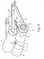
- the bobbin frame 40 has fixed thereto the functional part of the brake 22 of the second regulation system 14 represented by the strap 21 passing over the lateral ring 12 that is freely rotatable on the drive shaft 10 which also carries another freely rotatable unbraked ring 12 and the driven ring 11 which is in driving connection with the driven shaft 10 .
- the other end of the strap 21 is fixed to the adjustment member 23 , and its tension can be adjusted by the adjusting screw 24 .
- the yarn 2 passes through the distributor 35 and is laid into the winding of the cone 5 .
- the bobbin frame 40 has fixed thereto a control member 41 represented by a cam 42 with which is in contact a roller 43 connected with a lever 44 swinging around a fulcrum 45 .
- a spring 46 whose the other end is fixed to a stationary section 47 of the machine.
- Fixed to the arm of the lever 44 is the strap 21 of the brake 22 of the second regulation system 14 .
- the strap 21 passes over the step or groove 20 of the freely rotatable ring 12 of the rolling roller 4 and by means of this acts as its brake 22 .
- the other end of the strap 21 is adjustably connected to the stationary section 47 .
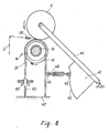
- the bobbin frame 40 has fixed thereto a control member 41 represented by the cam 42 .
- the roller 43 is connected with a bar 48 passing through a guiding 49 .
- a roller 50 is situated on the other end of the bar 48 , is in contact with the strap 21 of the brake 22 of the second regulation system 14 that passes over the step or the groove 28 of the freely rotatable ring 12 of the rolling roller 4 .
- One end of the strap 21 is fixed to the stationary section 47 of the machine, the other, to a stop 51 between which and the stationary section 47 is mounted an extension spring 52 .
- the described embodiments work as follows: In the embodiment shown in Fig. 4, the increasing diameter of the cone 5 progressively loosens the strap 21 with respect to the freely rotatable lateral ring 12 , thus reduces the braking effect of the brake 22 and increases the rotation velocity of the right-side freely rotatable ring 12 which is in contact with the small flange 36 of the cone 5 , and consequently displaces the pure rolling point towards this small flange 36 of the cone 5 with the ensuing increase in turning speed (rotation velocity) of the cone 5 resulting in the required correction of the traction force in the yarn 2 or in another material subject to the winding process.
- the strap 21 is subject to a varying force whose magnitude and course are defined by the shape of the cam 42 . Due to this varying force acting on the strap 21 , the braking effect of the brake 22 changes, i.e., increases or decreases, as the winding process is going on and the diameter of the cone 5 increases. In this way, the pure rolling point displacement towards the small flange 36 or towards the great flange can be pre-programmed by the shape of the cam 42 in accordance with the needed course of the traction force of the yarn 2 or of another material subject to winding throughout the winding process.
- the traction of the strap 21 can be adjusted for instance by means of the screw 24 (in embodiments shown in Figs. 4 and 5), or automatically by means of the extension spring 52 (in the embodiment shown in Fig. 6).
- the invention can be applied in the textile industry and has been experimentally tested.
- the embodiment shown in Fig. 1 has afforded a constant medium winding velocity of 140 m.min ⁇ 1 while winding a cone of 4 o 20 throughout the large flange diameter range from 65 to 300 mm.
- three predetermined courses of the traction force in the yarn 2 have been achieved (maintained), two of them decreasing and one of them slightly increasing, at the progressive increase in the diameter of the large flange of the cone 5 .
- the wound cones 5 were of high quality suitable for any subsequent technological operation.
Landscapes
- Engineering & Computer Science (AREA)
- Mechanical Engineering (AREA)
- Winding Filamentary Materials (AREA)
- Tension Adjustment In Filamentary Materials (AREA)
Applications Claiming Priority (4)
| Application Number | Priority Date | Filing Date | Title |
|---|---|---|---|
| CS353188A CS277297B6 (en) | 1988-05-25 | 1988-05-25 | Winding device, particularly of conical bobbins on textile machines. |
| CS3531/88 | 1988-05-25 | ||
| CS395888A CS277298B6 (en) | 1988-06-08 | 1988-06-08 | Winding device, particularly of conical bobbins on textile machines. |
| CS3958/88 | 1988-06-08 |
Publications (2)
| Publication Number | Publication Date |
|---|---|
| EP0343540A1 true EP0343540A1 (de) | 1989-11-29 |
| EP0343540B1 EP0343540B1 (de) | 1993-08-11 |
Family
ID=25745835
Family Applications (1)
| Application Number | Title | Priority Date | Filing Date |
|---|---|---|---|
| EP89109102A Expired - Lifetime EP0343540B1 (de) | 1988-05-25 | 1989-05-19 | Methode und Vorrichtung zur Aufwicklung von Garn zu einer konischen Spule für eine Textilmaschine mit konstanter Garnzufuhr |
Country Status (4)
| Country | Link |
|---|---|
| US (1) | US5035369A (de) |
| EP (1) | EP0343540B1 (de) |
| CN (1) | CN1022179C (de) |
| DE (1) | DE68908268T2 (de) |
Cited By (3)
| Publication number | Priority date | Publication date | Assignee | Title |
|---|---|---|---|---|
| DE4019443A1 (de) * | 1989-06-29 | 1991-01-31 | Elitex Liberec | Vorrichtung zum aufwickeln einer kegelspule, insbesondere auf einer textilmaschine mit konstanter garnzufuhr |
| DE4019444A1 (de) * | 1989-06-29 | 1991-01-31 | Elitex Liberec | Vorrichtung zum wickeln einer kegelspule, insbesondere auf einer textilmaschine mit konstanter garnzufuhr |
| EP1795477A1 (de) * | 2005-12-08 | 2007-06-13 | Murata Kikai Kabushiki Kaisha | Wickelmaschine |
Families Citing this family (12)
| Publication number | Priority date | Publication date | Assignee | Title |
|---|---|---|---|---|
| US5690707A (en) * | 1992-12-23 | 1997-11-25 | Minnesota Mining & Manufacturing Company | Abrasive grain comprising manganese oxide |
| WO1998033735A1 (en) | 1997-02-05 | 1998-08-06 | Plant Engineering Consultants, Inc. | Precision winding method and apparatus |
| DE59809204D1 (de) * | 1998-02-14 | 2003-09-11 | Volkmann Gmbh | Verfahren und Vorrichtung zur Garnaufwicklung auf einen konischen Spulenkörper |
| KR100621161B1 (ko) * | 2001-10-31 | 2006-09-13 | 말와 코튼 스피닝 밀스 엘티디. | 편물을 제조하는데 사용하기 위한 인디고 염색사를마련하는 방법 |
| US7007883B2 (en) * | 2003-02-05 | 2006-03-07 | Adalis Corporation | Apparatus and method for dispensing elongated material |
| ITMI20051325A1 (it) * | 2005-07-12 | 2007-01-13 | Btsr Int Spa | Metodo e dispositivo per assicurare l'alimentazione di un filo a tensione costante a doppio anello di regolazione ad una macchina tessile |
| US7467759B2 (en) * | 2005-09-13 | 2008-12-23 | Brown Maurice H | Adjustment mechanism for a wire tensioning apparatus |
| FI8941U1 (fi) * | 2010-04-27 | 2010-11-11 | Metso Paper Inc | Pätkätela-asennelma ja pätkätelan pysäytyslaite |
| JP2014218314A (ja) | 2013-05-01 | 2014-11-20 | 村田機械株式会社 | 糸巻取機 |
| CN106185451B (zh) * | 2016-07-20 | 2019-05-31 | 诺克威特种导体(常州)有限公司 | 一种无机械阻力放线装置 |
| CN106629246B (zh) * | 2017-02-11 | 2019-04-12 | 山东华纶新材料有限公司 | 一种纺织线纱张力控制设备 |
| CN109626078B (zh) * | 2019-02-02 | 2024-02-13 | 黄河科技学院 | 一种席梦思恒线速度辊压装置 |
Citations (5)
| Publication number | Priority date | Publication date | Assignee | Title |
|---|---|---|---|---|
| GB1249247A (en) * | 1968-12-09 | 1971-10-13 | Rieter Ag Maschf | Method of and apparatus for winding a yarn in which the yarn tension is controlled |
| DE1912374B2 (de) * | 1968-07-19 | 1974-01-17 | Veb Spinnereimaschinenbau Karlmarx-Stadt, X 9010 Karl-Marx-Stadt | Spulmaschine, insbesondere Kreuzspulmaschine |
| DE2458853A1 (de) * | 1974-12-12 | 1976-06-16 | Schlafhorst & Co W | Wickeleinrichtung fuer konische, durch friktion angetriebene kreuzspulen |
| DE3510495A1 (de) * | 1985-03-26 | 1986-09-25 | N P K "Tekstilno Mašinostroene", Gabrovo | Garnaufwickelvorrichtung |
| DE3718831A1 (de) * | 1987-06-05 | 1988-12-15 | Fritz Stahlecker | Vorrichtung zum antreiben konischer kreuzspulen |
Family Cites Families (3)
| Publication number | Priority date | Publication date | Assignee | Title |
|---|---|---|---|---|
| DE2454917C2 (de) * | 1974-11-20 | 1981-11-19 | W. Schlafhorst & Co, 4050 Mönchengladbach | Verfahren und Vorrichtung zum Wickeln konischer Kreuzspulen bei konstanter Fadenzuführgeschwindigkeit |
| EP0063690B1 (de) * | 1981-04-24 | 1985-07-24 | Maschinenfabrik Rieter Ag | Vorrichtung zum Aufwickeln eines Fadens |
| DE3422637A1 (de) * | 1984-06-19 | 1985-12-19 | Schubert & Salzer Maschinenfabrik Ag, 8070 Ingolstadt | Textilmaschine mit mehreren spulstellen zum aufwinden eines mit konstanter geschwindigkeit zugefuehrten fadens auf eine konische kreuzspule |
-
1989
- 1989-05-19 EP EP89109102A patent/EP0343540B1/de not_active Expired - Lifetime
- 1989-05-19 DE DE89109102T patent/DE68908268T2/de not_active Expired - Fee Related
- 1989-05-24 US US07/356,428 patent/US5035369A/en not_active Expired - Fee Related
- 1989-05-25 CN CN89103657.1A patent/CN1022179C/zh not_active Expired - Fee Related
Patent Citations (5)
| Publication number | Priority date | Publication date | Assignee | Title |
|---|---|---|---|---|
| DE1912374B2 (de) * | 1968-07-19 | 1974-01-17 | Veb Spinnereimaschinenbau Karlmarx-Stadt, X 9010 Karl-Marx-Stadt | Spulmaschine, insbesondere Kreuzspulmaschine |
| GB1249247A (en) * | 1968-12-09 | 1971-10-13 | Rieter Ag Maschf | Method of and apparatus for winding a yarn in which the yarn tension is controlled |
| DE2458853A1 (de) * | 1974-12-12 | 1976-06-16 | Schlafhorst & Co W | Wickeleinrichtung fuer konische, durch friktion angetriebene kreuzspulen |
| DE3510495A1 (de) * | 1985-03-26 | 1986-09-25 | N P K "Tekstilno Mašinostroene", Gabrovo | Garnaufwickelvorrichtung |
| DE3718831A1 (de) * | 1987-06-05 | 1988-12-15 | Fritz Stahlecker | Vorrichtung zum antreiben konischer kreuzspulen |
Cited By (3)
| Publication number | Priority date | Publication date | Assignee | Title |
|---|---|---|---|---|
| DE4019443A1 (de) * | 1989-06-29 | 1991-01-31 | Elitex Liberec | Vorrichtung zum aufwickeln einer kegelspule, insbesondere auf einer textilmaschine mit konstanter garnzufuhr |
| DE4019444A1 (de) * | 1989-06-29 | 1991-01-31 | Elitex Liberec | Vorrichtung zum wickeln einer kegelspule, insbesondere auf einer textilmaschine mit konstanter garnzufuhr |
| EP1795477A1 (de) * | 2005-12-08 | 2007-06-13 | Murata Kikai Kabushiki Kaisha | Wickelmaschine |
Also Published As
| Publication number | Publication date |
|---|---|
| DE68908268D1 (de) | 1993-09-16 |
| US5035369A (en) | 1991-07-30 |
| CN1040006A (zh) | 1990-02-28 |
| DE68908268T2 (de) | 1994-01-13 |
| CN1022179C (zh) | 1993-09-22 |
| EP0343540B1 (de) | 1993-08-11 |
Similar Documents
| Publication | Publication Date | Title |
|---|---|---|
| EP0343540A1 (de) | Methode und Vorrichtung zur Aufwicklung von Garn zu einer konischen Spule für eine Textilmaschine mit konstanter Garnzufuhr | |
| US3087689A (en) | Thread tensioning means for textile machines | |
| US4789107A (en) | Process and apparatus for winding a thread supplied at a constant speed onto a cross wound bobbin | |
| KR20010031957A (ko) | 자체 보정형 필라멘트 인장력 제어 디바이스 | |
| US4355747A (en) | Multi-purpose yarn feeding device | |
| US3945579A (en) | Winding mechanisms with friction drive rollers | |
| US3672584A (en) | Winding apparatus | |
| US5394684A (en) | Yarn storage mechanism | |
| CN1003783B (zh) | 以恒定速度供纱卷绕成交叉筒子的装置 | |
| US5277668A (en) | Gear transmissions, for textile machines | |
| US3672583A (en) | Winding apparatus and method | |
| EP0016942B1 (de) | Wickelmaschine | |
| US6895736B2 (en) | Thread-guiding device for collecting spun yarns on bobbins particularly for open-end spinning frames | |
| EP0246717A2 (de) | Webmaschine | |
| US4022390A (en) | Device for yarn spooling | |
| JP3141137B2 (ja) | 糸送り装置 | |
| US20050034279A1 (en) | Textile machine, in particular spinning mill preparation machine with a drafting equipment | |
| US5586427A (en) | Device for adjusting the contact pressure of a pressure roller against the draw-off shaft of a rotor spinning machine | |
| US3672589A (en) | Detection arrangement of winding speed on a take-up winder | |
| US3409243A (en) | Winding apparatus | |
| RU2008246C1 (ru) | Устройство для фрикционного наматывания пряжи на коническую паковку | |
| CN220300980U (zh) | 一种蕾丝经编机的放线装置 | |
| CZ397992A3 (cs) | Zařízení pro navíjení zejména kuželové cívky na textilním stroji s konstantní dodávkou příze | |
| JPH04341443A (ja) | ウェブの巻取り装置 | |
| SU914675A1 (ru) | Устройство для натяжения нитей на машине сновальной1 |
Legal Events
| Date | Code | Title | Description |
|---|---|---|---|
| PUAI | Public reference made under article 153(3) epc to a published international application that has entered the european phase |
Free format text: ORIGINAL CODE: 0009012 |
|
| AK | Designated contracting states |
Kind code of ref document: A1 Designated state(s): CH DE GB IT LI |
|
| 17P | Request for examination filed |
Effective date: 19900523 |
|
| 17Q | First examination report despatched |
Effective date: 19911223 |
|
| GRAA | (expected) grant |
Free format text: ORIGINAL CODE: 0009210 |
|
| ITF | It: translation for a ep patent filed | ||
| AK | Designated contracting states |
Kind code of ref document: B1 Designated state(s): CH DE GB IT LI |
|
| RBV | Designated contracting states (corrected) |
Designated state(s): CH DE IT LI |
|
| REF | Corresponds to: |
Ref document number: 68908268 Country of ref document: DE Date of ref document: 19930916 |
|
| PLBE | No opposition filed within time limit |
Free format text: ORIGINAL CODE: 0009261 |
|
| STAA | Information on the status of an ep patent application or granted ep patent |
Free format text: STATUS: NO OPPOSITION FILED WITHIN TIME LIMIT |
|
| 26N | No opposition filed | ||
| PGFP | Annual fee paid to national office [announced via postgrant information from national office to epo] |
Ref country code: CH Payment date: 19950720 Year of fee payment: 7 |
|
| PGFP | Annual fee paid to national office [announced via postgrant information from national office to epo] |
Ref country code: DE Payment date: 19950728 Year of fee payment: 7 |
|
| PG25 | Lapsed in a contracting state [announced via postgrant information from national office to epo] |
Ref country code: LI Effective date: 19960531 Ref country code: CH Effective date: 19960531 |
|
| REG | Reference to a national code |
Ref country code: CH Ref legal event code: PL |
|
| PG25 | Lapsed in a contracting state [announced via postgrant information from national office to epo] |
Ref country code: DE Effective date: 19970201 |
|
| PG25 | Lapsed in a contracting state [announced via postgrant information from national office to epo] |
Ref country code: IT Free format text: LAPSE BECAUSE OF NON-PAYMENT OF DUE FEES;WARNING: LAPSES OF ITALIAN PATENTS WITH EFFECTIVE DATE BEFORE 2007 MAY HAVE OCCURRED AT ANY TIME BEFORE 2007. THE CORRECT EFFECTIVE DATE MAY BE DIFFERENT FROM THE ONE RECORDED. Effective date: 20050519 |