EP0343407A1 - Apparatus for introducing matter to be fluidized to a fluid bed, particularly a drying plant - Google Patents
Apparatus for introducing matter to be fluidized to a fluid bed, particularly a drying plant Download PDFInfo
- Publication number
- EP0343407A1 EP0343407A1 EP89108086A EP89108086A EP0343407A1 EP 0343407 A1 EP0343407 A1 EP 0343407A1 EP 89108086 A EP89108086 A EP 89108086A EP 89108086 A EP89108086 A EP 89108086A EP 0343407 A1 EP0343407 A1 EP 0343407A1
- Authority
- EP
- European Patent Office
- Prior art keywords
- fluidized bed
- chute
- pendulum
- space
- fluidised bed
- Prior art date
- Legal status (The legal status is an assumption and is not a legal conclusion. Google has not performed a legal analysis and makes no representation as to the accuracy of the status listed.)
- Withdrawn
Links
Images

Classifications
-
- F—MECHANICAL ENGINEERING; LIGHTING; HEATING; WEAPONS; BLASTING
- F26—DRYING
- F26B—DRYING SOLID MATERIALS OR OBJECTS BY REMOVING LIQUID THEREFROM
- F26B3/00—Drying solid materials or objects by processes involving the application of heat
- F26B3/02—Drying solid materials or objects by processes involving the application of heat by convection, i.e. heat being conveyed from a heat source to the materials or objects to be dried by a gas or vapour, e.g. air
- F26B3/06—Drying solid materials or objects by processes involving the application of heat by convection, i.e. heat being conveyed from a heat source to the materials or objects to be dried by a gas or vapour, e.g. air the gas or vapour flowing through the materials or objects to be dried
- F26B3/08—Drying solid materials or objects by processes involving the application of heat by convection, i.e. heat being conveyed from a heat source to the materials or objects to be dried by a gas or vapour, e.g. air the gas or vapour flowing through the materials or objects to be dried so as to loosen them, e.g. to form a fluidised bed
-
- B—PERFORMING OPERATIONS; TRANSPORTING
- B01—PHYSICAL OR CHEMICAL PROCESSES OR APPARATUS IN GENERAL
- B01J—CHEMICAL OR PHYSICAL PROCESSES, e.g. CATALYSIS OR COLLOID CHEMISTRY; THEIR RELEVANT APPARATUS
- B01J8/00—Chemical or physical processes in general, conducted in the presence of fluids and solid particles; Apparatus for such processes
- B01J8/0015—Feeding of the particles in the reactor; Evacuation of the particles out of the reactor
- B01J8/002—Feeding of the particles in the reactor; Evacuation of the particles out of the reactor with a moving instrument
-
- B—PERFORMING OPERATIONS; TRANSPORTING
- B01—PHYSICAL OR CHEMICAL PROCESSES OR APPARATUS IN GENERAL
- B01J—CHEMICAL OR PHYSICAL PROCESSES, e.g. CATALYSIS OR COLLOID CHEMISTRY; THEIR RELEVANT APPARATUS
- B01J8/00—Chemical or physical processes in general, conducted in the presence of fluids and solid particles; Apparatus for such processes
- B01J8/0015—Feeding of the particles in the reactor; Evacuation of the particles out of the reactor
- B01J8/003—Feeding of the particles in the reactor; Evacuation of the particles out of the reactor in a downward flow
Definitions
- the invention relates to a device for introducing the material to be swirled into the mixing zone of a fluidized bed with a cellular wheel sluice arranged above the fluidized bed, in particular an entry device for an indirectly heated steam fluidized bed drying system in modular design for raw fine coal.
- the invention is characterized in that a pendulum chute is provided in the space between the rotary valve and the free surface of the fluidized bed, which covers a delimited mixing space of the fluidized bed.
- the pendulum chute consists of two steam-heated sheets arranged in a V-shape on a swivel bearing, the axis of the cellular wheel sluice and the swivel bearing of the pendulum chute preferably being normal to one another and arranged skewed to one another.
- a four-part fluidized bed drying system in elevation, in which the coal is introduced into a fluidized bed 3 via a rotary valve 2, a pendulum chute 4 being provided which enables a uniform distribution of the material to be fluidized in the fluidized bed without it being too local accumulations is coming.
- the pendulum chute 4 is mechanically driven, the pendulum movement being controlled by a curve template around the pivot bearing 6.
- the pendulum chute 4 and the axis of the rotary valve are arranged crossing one another, so that each cell content of the rotary valve is distributed over the surface of the mixing space 5 of the fluidized bed 3 by the oscillating movement of the chute.
- the rotary valve 2 is mounted so that the parabolic mass flow falls with its maximum on the center of the pivot bearing 6, which leads to the eccentric arrangement shown so that each mixing space 5 of each fluidized bed 3 is supplied approximately the same.
- the mixing room should be free from heating surfaces 12, so that flooding of the heating surfaces is possible at least in this area.
- the pendulum chute 4 consists of steam-heated sheet metal walls 7, as a result of which caking can largely be avoided.
- the fluidizing agent for the fluidized bed system is introduced through the channels 13 and distributed in the fluidized bed via the distribution channels 14.
- the fluidization medium rises from these distribution channels 14 to the heating surfaces, fluidizes the material to be treated and collects in the free space 1 above the fluidized bed, from where it is discharged via the evaporation channel 10 after dry cleaning and possibly after condensation of the absorbed moisture into the channels 13 is recirculated.
- the evaporation channel 10 is arranged centrally, so that it can operate several fluidized bed systems, although it is entirely desirable that the same immerses itself in the fluidized bed and thus divides the fluidized bed apparatus into two equally large dividing units which are operated by separate cellular wheel locks.
- the treated, in particular dried, material is discharged via the discharge funnel 9.
- the inlet openings of the evaporation duct are covered with a fence of baffle elements, preferably in several levels, so that a large part of the dust generated at the entry into the steam duct is prevented and is returned from the impact elements into the fluidized bed, the return being carried out in less heated zones, that is to say in downward flows.
- Such dryers are particularly suitable for drying raw fine coal with a grain size of 0 to 6 mm.
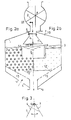
- FIG. 2 in contrast to FIG. 1, the mixing space 5 is kept small in relation to the surface of the fluidized bed and is delimited by baffles 11, the heating in the area of the mixing space, in particular below it, being less than in the other space of the fluidized bed.
- FIG. 2 also shows an inflow base 15 for uniform distribution of the fluidization medium over the entire base area of the fluidized bed dryer, leaving an outlet funnel 9 free.
Abstract
Description
Die Erfindung betrifft eine Vorrichtung zur Einbringung des zu verwirbelnden Gutes in die Mischungszone eines Wirbelbettes mit einer oberhalb des Wirbelbettes angeordneten Zellradschleuse, insbesondere Eintragsvorrichtung für eine indirekt beheizte Dampfwirbelschichttrocknungsanlage in Modulbauweise für Rohfeinkohle.The invention relates to a device for introducing the material to be swirled into the mixing zone of a fluidized bed with a cellular wheel sluice arranged above the fluidized bed, in particular an entry device for an indirectly heated steam fluidized bed drying system in modular design for raw fine coal.
Bei der Kohlentrocknung ist es bekannt (DD-PS 1,42.086, DD-PS 237.542 und DE-AS 23 42 184), die Kohle mittels einer Zellradschleuse oberhalb eines Wirbelbettes einzuschleusen und in das Wirbelbett einzubringen. Da die Höhe der Wirbelschicht aus verfahrenstechnischen Gründen begrenzt ist, ist es erforderlich, Trocknungsanlagen mit großen Querschnittsflächen zu bauen, um die Wirtschaftlichkeit der Anlage zu gewährleisten. Hiebei treten durch die Anordnung nur einer Zuführungsschleuse Probleme auf, da im Bereich der Aufgabe die Wirbelschicht zum Erliegen kommt. Es ist daher aus der DD-PS 253.472 eine Vorrichtung zur Verteilung von Rohfeinkohle in einem Wirbelschichttrockner bekannt, die aus dem Trogkettenförderer besteht, der die Kohle innerhalb der Trocknungsanlage verteilt. Der Nachteil dieser Vorrichtung ist, daß dieser Trogkettenförderer die Kohle praktisch über die gesamte Länge des Trockners transportiert, wobei die Fallöcher durch die feuchte Rohfeinkohle sich während des Betriebs teilweise zusetzen und somit keine gleichmäßige Verteilung der Kohle gewährleistet werden kann.In coal drying, it is known (DD-
Es ist daher ein Ziel der Erfindung, unter Vermeidung von zu aufwendiger Mechanik das zu trocknende Gut möglichst gleichmäßig über den gesamten Eintragsquerschnitt der Wirbelschichttrocknungsanlage zu verteilen, um örtliche Überlastungen zu vermeiden.It is therefore an object of the invention, while avoiding mechanics that are too complex, to distribute the material to be dried as evenly as possible over the entire entry cross section of the fluidized bed drying system in order to avoid local overloads.
Die Erfindung ist dadurch gekennzeichnet, daß im Raum zwischen Zellradschleuse und der freien Oberfläche des Wirbelbettes eine Pendelschurre vorgesehen ist, die einen abgegrenzten Mischungsraum des Wirbelbettes bestreicht. Insbesondere besteht die Pendelschurre aus zwei dampfbeheizten an einem Schwenklager V-förmig angeordneten Blechen, wobei vorzugsweise die Achse der Zellradschleuse und das Schwenklager der Pendelschurre aufeinander normal stehen und zueinander windschief angeordnet sind. Weitere wesentliche Erfindungsmaßnahmen sind in den Unteransprüchen 4 bis 9 angegeben.The invention is characterized in that a pendulum chute is provided in the space between the rotary valve and the free surface of the fluidized bed, which covers a delimited mixing space of the fluidized bed. In particular, the pendulum chute consists of two steam-heated sheets arranged in a V-shape on a swivel bearing, the axis of the cellular wheel sluice and the swivel bearing of the pendulum chute preferably being normal to one another and arranged skewed to one another. Further essential measures of the invention are specified in subclaims 4 to 9.
Die Erfindung wird in Form von zwei Beispielen in 3 Figuren beschrieben und schematisch illustriert.
- Fig. 1 zeigt eine Trocknungsanlage in Modulbauweise, bei der vier Wirbelbetttrockner durch zwei Eintragsvorrichtungen und eine gemeinsame Abgasentsorgung bedient werden.
- Fig. 2 zeigt in der Teilfigur 2a (links) einen Wirbelbetttrockner mit einem rohrförmigen Heizregister und in Fig. 2b mit einem
plattenförmigen Heizregister 12′, wobei ein spezielles Eintragswirbelbett unter Bildung eines Mischungsraumes verwendet wird. - Fig. 3 zeigt einen Schnitt durch die Pendelschurre gemäß Schnittlinie II - II in Fig. 2.
- Fig. 1 shows a drying system in modular design, in which four fluid bed dryers are operated by two entry devices and a common waste gas disposal.
- Fig. 2 shows in part 2a (left) a fluidized bed dryer with a tubular heating register and in Fig. 2b with a plate-shaped heating register 12 ', a special entry fluidized bed being used to form a mixing space.
- FIG. 3 shows a section through the pendulum chute according to section line II-II in FIG. 2.
In Fig. 1 ist eine vierteilige Wirbelbetttrocknungsanlage im Aufriß geoffenbart, bei der die Kohle über eine Zellradschleuse 2 in ein Wirbelbett 3 eingebracht wird, wobei eine Pendelschurre 4 vorgesehen ist, die eine gleichmäßige Verteilung des zu verwirbelnden Gutes im Wirbelbett ermöglicht, ohne daß es zu lokalen Anhäufungen kommt. Zu diesem Zweck ist die Pendelschurre 4 mechanisch angetrieben, wobei die Pendelbewegung durch eine Kurvenschablone um das Schwenklager 6 gesteuert wird. Die Pendelschurre 4 und die Achse der Zellradschleuse in einander kreuzend angeordnet, so daß jeder Zelleninhalt der Zellradschleuse durch die pendelnde Bewegung der Schurre über die Oberfläche des Mischungsraumes 5 des Wirbelbettes 3 verteilt wird. Die Zellradschleuse 2 ist so montiert, daß der parabelförmige Massenfluß mit seinem Maximum auf die Mitte des Schwenklagers 6 fällt, wodurch es zur dargestellten exzentrischen Anordnung kommt, damit jeder Mischungsraum 5 jedes Wirbelbettes 3 etwa gleich versorgt wird. Der Mischungsraum sollte frei von Heizflächen 12 sein, so daß eine Überflutung der Heizflächen zumindest in diesem Bereich möglich ist. Die Pendelschurre 4 besteht aus dampfbeheizten Blechwänden7, wodurch Anbackungen weitgehend vermieden werden können. Das Fluidisierungsmittel für die Wirbelbettanlage wird durch die Kanäle 13 eingebracht und über die Verteilkanäle 14 im Wirbelbett verteilt. Das Fluidisierungsmedium steigt von diesen Verteilkanälen 14 zu den Heizflächen empor, fluidisiert das zu behandelnde Gut und sammelt sich im Freiraum 1 oberhalb des Wirbelbettes, von wo es über den Abdampfkanal 10 nach einer Trockenreinigung abgeführt und eventuell nach einer Auskondensation der aufgenommenen Feuchtigkeit in die Kanäle 13 rezirkuliert wird. Der Abdampfkanal 10 ist dabei zentral angeordnet, so daß er mehrere Wirbelbettanlagen bedienen kann, wobei es durchaus wünschenswert ist, daß derselbe in die Wirbelschicht eintaucht und so den Wirbelschichtapparat in zwei gleich große Teilapparate unterteilt, die durch getrennte Zellradschleusen bedient werden. Die Abführung des behandelten, insbesondere getrockneten Gutes erfolgt über den Austragstrichter 9. Zur Vermeidung der Staubbelastung im Abdampfkanal sind die Eintragsöffnungen des Abdampfkanals mit einem Zaun von Prallelementen, vorzugsweise in mehreren Ebenen, abgedeckt, so daß ein Großteil des erzeugten Staubes am Eintritt in den Dampfkanal gehindert wird und von den Prallelementen in das Wirbelbett rückgeführt wird, wobei die Rückbringung in wenigt beheizte Zonen, also in nach abwärts führenden Strömungen, erfolgt. Derartige Trockner eignen sich besonders zur Trocknung von Rohfeinkohle mit einer Körnung von 0 bis 6 mm.In Fig. 1, a four-part fluidized bed drying system is disclosed in elevation, in which the coal is introduced into a fluidized
In Fig. 2 ist im Gegensatz zur Fig. 1 der Mischungsraum 5 im Verhältnis zur Oberfläche des Wirbelbettes klein gehalten und durch Tauchwände 11 begrenzt, wobei die Beheizung im Bereich des Mischungsraumes, insbesondere unterhalb desselben, geringer ist als im sonstigen Raum des Wirbelbettes. Ferner zeigt die Fig. 2 einen Anströmboden 15 zur gleichmäßigen Verteilung des Fluidisierungsmediums über die gesamte Grundfläche des Wirbelbetttrockners unter Freilassung eines Auslauftrichters 9.In FIG. 2, in contrast to FIG. 1, the
Claims (9)
Applications Claiming Priority (2)
| Application Number | Priority Date | Filing Date | Title |
|---|---|---|---|
| DD31566588A DD271945A1 (en) | 1988-05-11 | 1988-05-11 | DEVICE FOR DISTRIBUTING THE IMPORTED GOODS THROUGH A SWIVEL LAYER |
| DD315665 | 1988-05-11 |
Publications (1)
| Publication Number | Publication Date |
|---|---|
| EP0343407A1 true EP0343407A1 (en) | 1989-11-29 |
Family
ID=5599171
Family Applications (1)
| Application Number | Title | Priority Date | Filing Date |
|---|---|---|---|
| EP89108086A Withdrawn EP0343407A1 (en) | 1988-05-11 | 1989-05-05 | Apparatus for introducing matter to be fluidized to a fluid bed, particularly a drying plant |
Country Status (2)
| Country | Link |
|---|---|
| EP (1) | EP0343407A1 (en) |
| DD (1) | DD271945A1 (en) |
Cited By (9)
| Publication number | Priority date | Publication date | Assignee | Title |
|---|---|---|---|---|
| EP0819904A1 (en) * | 1996-07-17 | 1998-01-21 | GEA Wärme- und Umwelttechnik GmbH | Steam fluidized bed drying plant |
| EP0819901A1 (en) * | 1996-07-17 | 1998-01-21 | GEA Wärme- und Umwelttechnik GmbH | Browncoal drying plant |
| EP0819903A1 (en) * | 1996-07-17 | 1998-01-21 | GEA Wärme- und Umwelttechnik GmbH | Brown coal drying plant |
| EP0819902A1 (en) * | 1996-07-17 | 1998-01-21 | GEA Wärme- und Umwelttechnik GmbH | Plant for steam fluidized bed drying |
| EP0819900A1 (en) * | 1996-07-17 | 1998-01-21 | GEA Wärme- und Umwelttechnik GmbH | Installation for vapor-fed fluidised-bed drying of crude lignite |
| EP0843141A1 (en) * | 1996-11-19 | 1998-05-20 | GEA Wärme- und Umwelttechnik GmbH | Coal feeding device for a brown coal drying plant |
| WO2001036887A1 (en) * | 1999-11-15 | 2001-05-25 | Energy Engineering International (Pty) Ltd. | A fluidized bed apparatus |
| WO2017050310A1 (en) * | 2015-09-24 | 2017-03-30 | Hugo Nienhaus | Environmentally-friendly, self-regulating system for continuously producing biochar with a high yield and consistently high quality from biomass and method for producing said biochar |
| CN108800758A (en) * | 2018-04-28 | 2018-11-13 | 北京长峰金鼎科技有限公司 | A kind of multichannel fluid bed and its drying means |
Citations (2)
| Publication number | Priority date | Publication date | Assignee | Title |
|---|---|---|---|---|
| FR1061250A (en) * | 1952-08-05 | 1954-04-09 | Didier Kogag Hinselmann Koksofenbau Gasverwertung Ag | Method and apparatus for introducing compact charges of coal into chambers of coke ovens and gas-generating ovens |
| DE2342184A1 (en) * | 1972-08-23 | 1974-03-14 | Waagner Biro Ag | METHOD AND DEVICE FOR DRYING COAL |
-
1988
- 1988-05-11 DD DD31566588A patent/DD271945A1/en not_active IP Right Cessation
-
1989
- 1989-05-05 EP EP89108086A patent/EP0343407A1/en not_active Withdrawn
Patent Citations (2)
| Publication number | Priority date | Publication date | Assignee | Title |
|---|---|---|---|---|
| FR1061250A (en) * | 1952-08-05 | 1954-04-09 | Didier Kogag Hinselmann Koksofenbau Gasverwertung Ag | Method and apparatus for introducing compact charges of coal into chambers of coke ovens and gas-generating ovens |
| DE2342184A1 (en) * | 1972-08-23 | 1974-03-14 | Waagner Biro Ag | METHOD AND DEVICE FOR DRYING COAL |
Non-Patent Citations (1)
| Title |
|---|
| PATENT ABSTRACTS OF JAPAN, Band 8, Nr. 218 (C-245)[1655], 4. Oktober 1984; & JP-A-59 104 411 (KAWASAKI SEITETSU K.K.) 16.06.1984 * |
Cited By (9)
| Publication number | Priority date | Publication date | Assignee | Title |
|---|---|---|---|---|
| EP0819904A1 (en) * | 1996-07-17 | 1998-01-21 | GEA Wärme- und Umwelttechnik GmbH | Steam fluidized bed drying plant |
| EP0819901A1 (en) * | 1996-07-17 | 1998-01-21 | GEA Wärme- und Umwelttechnik GmbH | Browncoal drying plant |
| EP0819903A1 (en) * | 1996-07-17 | 1998-01-21 | GEA Wärme- und Umwelttechnik GmbH | Brown coal drying plant |
| EP0819902A1 (en) * | 1996-07-17 | 1998-01-21 | GEA Wärme- und Umwelttechnik GmbH | Plant for steam fluidized bed drying |
| EP0819900A1 (en) * | 1996-07-17 | 1998-01-21 | GEA Wärme- und Umwelttechnik GmbH | Installation for vapor-fed fluidised-bed drying of crude lignite |
| EP0843141A1 (en) * | 1996-11-19 | 1998-05-20 | GEA Wärme- und Umwelttechnik GmbH | Coal feeding device for a brown coal drying plant |
| WO2001036887A1 (en) * | 1999-11-15 | 2001-05-25 | Energy Engineering International (Pty) Ltd. | A fluidized bed apparatus |
| WO2017050310A1 (en) * | 2015-09-24 | 2017-03-30 | Hugo Nienhaus | Environmentally-friendly, self-regulating system for continuously producing biochar with a high yield and consistently high quality from biomass and method for producing said biochar |
| CN108800758A (en) * | 2018-04-28 | 2018-11-13 | 北京长峰金鼎科技有限公司 | A kind of multichannel fluid bed and its drying means |
Also Published As
| Publication number | Publication date |
|---|---|
| DD271945A1 (en) | 1989-09-20 |
Similar Documents
| Publication | Publication Date | Title |
|---|---|---|
| EP0574675B1 (en) | Moving bed reactor installation | |
| EP3486591B1 (en) | Fluidized bed evaporation drier | |
| DE2821770A1 (en) | GRAIN DRYERS | |
| EP0357653B1 (en) | Feed inlet floor for mobile bed reactors | |
| DE2744449C2 (en) | Device for controlling the flow of granular material through a drying tower | |
| EP0343407A1 (en) | Apparatus for introducing matter to be fluidized to a fluid bed, particularly a drying plant | |
| DE2654107A1 (en) | FLUID BED PROCESS AND EQUIPMENT | |
| EP1452224B1 (en) | Tunnel-like device for treating a particulate material | |
| DE2100248C3 (en) | Device for heat, cold and / or material treatment of granular, free-flowing goods | |
| EP0039039B1 (en) | Apparatus for heat treating, particularly drying of pulverized bulk material | |
| DE7116731U (en) | DEVICE FOR DRY SORTING AND SEPARATE DISPOSAL OF GRAINY BULK MATERIAL | |
| DE2627262C3 (en) | Device for drying solids transported by a flowing gas | |
| EP0382742B1 (en) | Process of guiding a stream of bulk solids in at least one circulating bed reactor and reactor installation for realising the process | |
| DE3029398C2 (en) | Process for drying and preheating of moist fine goods and device for carrying out the process | |
| DE3110156C2 (en) | Device for drying and / or preheating fine-grained and / or dust-like solids | |
| DE19647025A1 (en) | Washing and/or drying and/or cleaning of recycled plastics products | |
| EP0197171B1 (en) | Low-temperature dryer for pressed fibrous material | |
| DE3302598C2 (en) | ||
| DE2243670C3 (en) | Process and fluid bed dryer for the continuous drying of granular materials | |
| DE2533914A1 (en) | Multiple-hearth drier for fine particulate material - esp. for dewatering pulverised coking coal | |
| DD253287A1 (en) | DEVICE FOR EXPORTING DRY GOODS FROM SWITCHING-LAYER DRYING SYSTEMS | |
| AT50883B (en) | Steam dryer for diffusion cuts, malt, oilseeds, fruit and the like. | |
| DE965779C (en) | Device for the continuous treatment of granular materials with gases, especially for cooling or drying | |
| DD264971A1 (en) | DEVICE FOR THE INTENSE MIXTURE OF SURFACE-HARDENED RAW COAL WITH DISPOSED DRY FEED AND THE SWIVEL LAYER | |
| DD216195A1 (en) | DEVICE FOR DRYING GRANULES FROM PLASTIC MASSES |
Legal Events
| Date | Code | Title | Description |
|---|---|---|---|
| PUAI | Public reference made under article 153(3) epc to a published international application that has entered the european phase |
Free format text: ORIGINAL CODE: 0009012 |
|
| AK | Designated contracting states |
Kind code of ref document: A1 Designated state(s): AT BE CH DE ES FR GB GR IT LI LU NL SE |
|
| 17P | Request for examination filed |
Effective date: 19900510 |
|
| 17Q | First examination report despatched |
Effective date: 19910208 |
|
| STAA | Information on the status of an ep patent application or granted ep patent |
Free format text: STATUS: THE APPLICATION IS DEEMED TO BE WITHDRAWN |
|
| 18D | Application deemed to be withdrawn |
Effective date: 19910619 |