EP0819901A1 - Browncoal drying plant - Google Patents
Browncoal drying plant Download PDFInfo
- Publication number
- EP0819901A1 EP0819901A1 EP96118517A EP96118517A EP0819901A1 EP 0819901 A1 EP0819901 A1 EP 0819901A1 EP 96118517 A EP96118517 A EP 96118517A EP 96118517 A EP96118517 A EP 96118517A EP 0819901 A1 EP0819901 A1 EP 0819901A1
- Authority
- EP
- European Patent Office
- Prior art keywords
- unit
- steam
- drying
- units
- fluidized bed
- Prior art date
- Legal status (The legal status is an assumption and is not a legal conclusion. Google has not performed a legal analysis and makes no representation as to the accuracy of the status listed.)
- Withdrawn
Links
Images

Classifications
-
- F—MECHANICAL ENGINEERING; LIGHTING; HEATING; WEAPONS; BLASTING
- F26—DRYING
- F26B—DRYING SOLID MATERIALS OR OBJECTS BY REMOVING LIQUID THEREFROM
- F26B3/00—Drying solid materials or objects by processes involving the application of heat
- F26B3/02—Drying solid materials or objects by processes involving the application of heat by convection, i.e. heat being conveyed from a heat source to the materials or objects to be dried by a gas or vapour, e.g. air
- F26B3/06—Drying solid materials or objects by processes involving the application of heat by convection, i.e. heat being conveyed from a heat source to the materials or objects to be dried by a gas or vapour, e.g. air the gas or vapour flowing through the materials or objects to be dried
- F26B3/08—Drying solid materials or objects by processes involving the application of heat by convection, i.e. heat being conveyed from a heat source to the materials or objects to be dried by a gas or vapour, e.g. air the gas or vapour flowing through the materials or objects to be dried so as to loosen them, e.g. to form a fluidised bed
- F26B3/084—Drying solid materials or objects by processes involving the application of heat by convection, i.e. heat being conveyed from a heat source to the materials or objects to be dried by a gas or vapour, e.g. air the gas or vapour flowing through the materials or objects to be dried so as to loosen them, e.g. to form a fluidised bed with heat exchange taking place in the fluidised bed, e.g. combined direct and indirect heat exchange
-
- F—MECHANICAL ENGINEERING; LIGHTING; HEATING; WEAPONS; BLASTING
- F26—DRYING
- F26B—DRYING SOLID MATERIALS OR OBJECTS BY REMOVING LIQUID THEREFROM
- F26B3/00—Drying solid materials or objects by processes involving the application of heat
- F26B3/02—Drying solid materials or objects by processes involving the application of heat by convection, i.e. heat being conveyed from a heat source to the materials or objects to be dried by a gas or vapour, e.g. air
- F26B3/06—Drying solid materials or objects by processes involving the application of heat by convection, i.e. heat being conveyed from a heat source to the materials or objects to be dried by a gas or vapour, e.g. air the gas or vapour flowing through the materials or objects to be dried
- F26B3/08—Drying solid materials or objects by processes involving the application of heat by convection, i.e. heat being conveyed from a heat source to the materials or objects to be dried by a gas or vapour, e.g. air the gas or vapour flowing through the materials or objects to be dried so as to loosen them, e.g. to form a fluidised bed
Definitions
- the invention relates to a system for steam fluidized bed drying broken raw lignite according to the Features in the preamble of claim 1.
- the upstream is separate for this power plant technology Drying is essential.
- Drying is essential. The possible increase in efficiency through an energetically favorable The greater the drying process, the higher the drying process water content to be reduced.
- Each drying unit includes a modular design a trigger unit in a vertical stacking arrangement for dried brown coal, one nozzle base unit, one Heat exchanger unit, a steam fluidized bed dryer unit and a feed unit for raw lignite.
- This concept ensures that the availability of a Power plant with more than 7500 operating hours per year is not affected by the coal predrying.
- the object of the invention is one by the features in the preamble of the claim 1 characterized lignite drying plant to improve system technology and economically.
- the internals are expediently by at least one single-layer grate bottom unit formed, as provided for in claim 3.
- Such a grate floor unit can cross from the hydro-steam flow arranged profile bodies, such as angle irons and the like exist.
- the arrangement and passage openings are targeted at the hydro-steam cycle depending on the system parameters Voted.
- each heat exchanger unit comprises Heat exchanger tubes that go to the horizontal are inclined.
- the heat exchanger tubes are fed with heating steam. This condenses on the inner walls due to the cooling heat transfer during drying. The inclination of the Heat exchanger tubes ensure a continuous drain the resulting condensate.
- the fluidized bed or the large one Fluidized bed area of a drying unit divided on several, preferably two smaller areas in the Fluidized bed cells. In this way, stable and homogeneous fluid bed operating conditions guaranteed. This leads to intense heat transfer and one high drying success.
- the two fluidized bed cells of a drying unit is assigned to a common bundle of heat exchanger tubes.
- the heat exchanger tubes are through openings in guided the partition, so that the partition in addition Carrying and stabilizing function takes over.
- the bundles are easily accessible from the outside. Steam pipes are not cut. This leads to in particular Maintenance or repair measures for advantages.
- Elliptical heat exchanger tubes are preferably used Commitment. Elliptical tubes have the advantage that at same heating bed volume can be. They are also easy to clean, because adhering carbon particles easily detach.
- the task unit then comprises at least one cellular wheel sluice, which is followed by a chain scraper conveyor is.
- a chain scraper conveyor When connected from several drying units Drying lines are convenient several cellular wheel sluices and several chain scraper conveyors intended.
- the cellular wheel sluices and the chain scraper conveyors are in a closed pre-treatment room arranged. This is above the Drying units and is therefore outside of the hydrocarbon atmosphere.
- the pre-treatment room can be used in many different ways are heated, for example by means of steam or hot air.
- the chain scraper conveyor is also heated possible.
- the cold wet brown coal which withdrawn from a storage bunker and over the cellular wheel locks reaches the chain scraper conveyor, preheated will.
- Preheating wet lignite improves their flow behavior and the tendency to stick is greatly reduced. Consequently, malfunctions prevented by dirt and blockages.
- the preheating of the wet lignite contributes to further increase in stability in the fluidized bed at.
- the wet lignite is removed from the fluidized bed cells Chain scraper conveyors fed via discharge chutes. There are openings in the bottom of the chain scraper conveyor for this purpose provided, the opening cross section adjustable by slide is. In this way, the application of the individual fluidized bed cells depending on the operating conditions being controlled.
- the modular design of the drying units lets in high level of workshop manufacturing too. Every module is passed from a housing in which the function determining Internals can be integrated.
- the modules preferably have Rectangular cross sections.
- the prefabricated modules can be broken down completely or into smaller units without great logistical and transport engineering effort for Power plant location brought and installed there.
- the construction of the respective module elements is different Performance sizes can be used without new designs to have to make.
- the installation and removal of individual Components of the modules is simple. This also leads to a significant simplification of maintenance or repair work. Even if one drying unit fails the entire system can remain in operation.
- drying units can be operated with low system pressures.
- pressure vessels can be dispensed with.
- this is from above via the feed unit continuously supplied raw lignite from the fluidizing medium flows from bottom to top.
- a vortex medium becomes the hydro-steam expelled from the raw lignite utilized.
- the amount of vortex medium and the Flow rates are adjusted so that the raw brown coal bed passes into the fluidized bed.
- the Vortex speed is above the vortex point and remains approximately independent of the coal mass flow. This is achieved through a steam cycle, at least to overcome the flow losses another blower that is always part of the hydro steam in circulation.
- Incoming steam becomes pressure dependent overheated with a small temperature difference.
- the weight of the lignite grains is in the fluidized bed by the opposite flow force of the vortex medium almost canceled.
- the fluidized Lignite coal then behaves like a liquid and flows through the heat exchanger unit. Here an intensive heat transfer takes place high turbulence instead and that contained in the raw lignite Water is evaporated. This way, a reliable one Drying the raw lignite to almost any residual water content can be achieved.
- Steam collecting chamber formed dryer line can furthermore the nozzle base units, the heat exchanger units and the steam fluidized bed dryer units two drying units arranged side by side each have a common partition.
- At least the outer walls of the steam fluidized bed dryer units, the steam collection chamber, the feed units and / or the extraction units can be heated be designed. In this way, caking can occur be avoided on the inner surfaces.
- the heating temperature is chosen so that it is above the condensation temperature of the hydro-steam contained in the system. Condensation of the steam on the inner surfaces becomes consequently prevents and sticking of coal dust in Condensate film prevented.
- the heating is expediently laid externally Heating pipe coils realized.
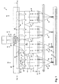
- FIGs 1 to 3 show one out of a total of eight Drying units 1-8 existing dryer line 9. How the individual can be seen from FIG Drying units 1-8 in pairs in groups 10, 11, 12, 13 interconnected.
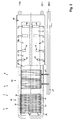
- Figure 2 illustrates the Construction of a drying unit 1-8.
- a trigger unit is arranged vertically one above the other 14 for dried brown coal TBK, a nozzle base unit 15, a heat exchanger unit 16, a steam fluidized bed dryer unit 17 and a task unit 18 for the wet raw lignite FBK.
- Each heat exchanger unit 16 is vertical by one aligned partition 19 in two vertically aligned Fluidized bed cells 20, 21 divided. With that, dryer street 9 shown here a total of sixteen Fluid bed cells 20, 21.
- a common vapor collection chamber 22 is arranged above the steam fluidized bed dryer units 17 .
- Output side of the steam fluidized bed dryer units 17 are internals 23 in the form of grate floor units 24 intended.
- the grate floor units 24 consist of two Layers of one another and offset from one another Angle profiles 25.
- the internals 23 cause one Pressure loss in the drying units 1-8, so that a Uniformization of the volume flow in all drying units 1-8 is done.
- all drying units 1-8 always almost the same amount of hydro-steam KWD deducted, regardless of how far the individual drying units 1-8 from the location the outlet 26 of the vapor collection chamber 22 are removed.
- the internals 23 take on a cleaning function, entrained dust from your hydro-steam KWD is deposited on them.
- Purified hydro-steam KWD is used as a fluidizing medium WM returned to the system via the nozzle base unit 15. Furthermore, the cleaned and heated hydro steam KWD as heating steam HD for the heat exchanger unit 16 can be used.
- each drying unit becomes 1-8 damp Lignite FBK in a grain size range from 0 to 10 mm fed by the task unit 18.
- the feed unit 18 is carried out from the bunker 27 Wet brown coal fed FBK. Arrived from bunker 27 the wet lignite FBK via four bunker funnels 28-31 in four rotary locks 32-35. These give the wet lignite FBK on four chain scraper conveyors 36-39.
- the rotary valve 32-35 and the chain scraper conveyor 36-39 are in a closed pre-treatment room 40, the drying units above 1-8 the steam collection chamber 22 is arranged.
- the pre-treatment room 40 can be heated so that preheating the FBK wet brown coal can be made.
- the Preheating improves the flow behavior of the wet lignite FBK. Since the pre-treatment room 40 is outside the hydro-steam atmosphere, it can easily also during the operation of the drying system Maintenance or repair purposes.
- the FBK passes through the discharge chutes 41, 42 Steam collection chamber 22 and enters the steam fluidized bed dryer unit 17th
- the wet lignite FBK then falls down against it upward flowing vortex medium WM.
- a vortex medium WM comes the expelled from the FBK wet brown coal and cleaned hydro-steam KWD used.
- the steam fluidized bed dryer unit 17 comprises one Chamber 53 which widens in a trapezoidal shape.
- the cross-sectional expansion will reduce the speed of the hydro-steam flowing upwards KWD reached. This will remove fine grain reduced.
- the heat exchanger unit 16 is arranged below the steam fluidized bed dryer unit 17 below the heat exchanger unit 16 is arranged below the Heat exchanger unit 16 is arranged. Above the Heat exchanger unit 16 passes the brown coal bed into the fluidized bed through the heat exchanger unit 16 continues. The fluidized brown coal then flows through the fluidized bed cells 20, 21.
- Heat exchanger tubes 56, 57 integrated. Every heat exchanger tube 56, 57 has longitudinal tube sections inclined to the horizontal 58, 59 on the vertical pipe sections 60, 61 merge.
- the heat exchanger tubes 56, 57 summarized in a tube sheet 62.
- the steam distribution chamber 63, 64 and the condensate collection chambers 65, 66 each bundle 54, 55 are arranged on the same side.
- Via a steam manifold 67 and the manifold 68 is fed to the steam distribution chambers 63, 64 heating steam HD.
- the condensate K occurs into the condensate collection chambers 65, 66 and is about deductions 69, 70 removed.
- Each heat exchanger unit 16 is separated by a partition 19 divided into two fluidized bed cells 20, 21.
- the Partition 19 is penetrated by bundles 54, 55.
- the partition 19 to the cross section of the Heat exchanger tubes 56, 57 provided adapted openings.
- the heat exchanger tubes 56, 57 are through the openings passed through. They are carried by the partition 19 and stabilized.
- a unit from bundles 54, 55, partition 19, tube sheet 62 and steam collecting chambers 63, 64 and condensate collecting chambers 65, 66 can be pre-assembled in the heat exchanger unit 16 can be installed transversely.
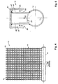
- nozzle base unit 15 there are two grate nozzle bases 71, 72 incorporated. As shown in Figure 4, everyone exists Grate nozzle base 71, 72 from a row parallel and side by side horizontal nozzle pipes 73.
- the grate nozzle bottoms 71, 72 are inserted into the nozzle base unit from one side 15 inserted.
- the loading of the grate nozzle bottoms 71, 72 with vortex medium WM is carried out from the vortex medium ring line 74 from via the feed lines 75, 76 and the Distribution lines 77, 78.
- the vortex medium WM then occurs out through nozzles 79 and flows up through the fluidized bed cells 20, 21.
- FIG. 5 shows the structure of a nozzle 79.
- the nozzle 79 includes a nozzle tube 73 fixed to the vertically upward nozzle 80, which by a Cap 81 is closed. At the top 82 are radial Nozzle openings 83, 84 arranged.
- the vortex medium WM passes through an opening 85 in the nozzle tube 73 in the nozzle 80 and flows through the nozzle openings 83, 84 radially. This is where the vortex medium gets WM in a between socket 80 and cap wall 86 located in the annular space 87. In the annular space 87, the vortex medium WM first flow downwards before crossing the Annular gap 88 can emerge. Through this training the Nozzle 79 is avoided that fine-grained brown coal in the Nozzle openings 83, 84 can flow. This will cause constipation the nozzle tubes 73 prevented.
- hydro-steam KWD as a fluidizing medium WM on the nozzle base unit 15 and the grate nozzle bases 71, 72 initiated. This depends on the pressure overheated with a small temperature difference.
- Hydro-steam KWD flows through the wet lignite FBK on the way through the heat exchanger unit 16 or the fluidized bed cells 20, 21 and the steam fluidized bed dryer unit 17 from bottom to top.
- the lignite to be dried is Hydro-steam KWD in a suspended state transferred.
- the amount of hydro-steam introduced KWD and the inflow speed are designed so that in Area above the heat exchanger unit 16 a homogeneous fluidized bed is created, which is characterized by the heat exchanger unit 16 or the fluidized bed cells 20, 21 continues. There is extraordinary in this flight stream favorable conditions for heat transfer. On the way through the heat exchanger unit 16 is from the downward flowing brown coal evaporates hydrocarbon and the water content is reduced to approx. 10% residual moisture.
- the driven hydro-steam KWD of all drying units 1-8 then gets into the steam collection chamber 22 and from there via outlet 26 for aftertreatment.
- Excess steam can flow from the circulatory system to the Balance the mass balance to be taken to the pressure to keep constant in the drying units 1-8.
- Excess steam can be used as heating steam HD or otherwise will.
- a trigger unit 14 is two Drying units 1, 2; 3, 4; 5, 6; 7, 8 assigned.
- the withdrawal takes place via a screw conveyor 89 with two oppositely aligned spiral sections 90, 91 and a rotary valve 92.
- the side walls 93, 94 of the trigger unit 14 are in the direction of the screw conveyor 89 inclined so that the dried brown coal TBK easily can flow to the screw conveyor 89.
- the cellular wheel locks 92 of the individual extraction units 14 carry the dry lignite TBK on a discharge conveyor 95 from where the dry brown coal TBK to Further use in the power plant process is brought.
- a discharge conveyor 95 extends below the drying units 1-8 in an encapsulated discharge space 96, which, if necessary, for inerting and / or cooling the Dry lignite TBK can be used.
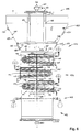
- the drying unit 101 consists of functionally coordinated Modules with trigger unit 102, nozzle base unit 103, heat exchanger unit 104, steam fluidized bed dryer unit 105 and task unit 106.
- drying units 101 are in turn one Lignite drying plant interconnected.
- the too drying amount of wet brown coal for a power plant is divided into several drying units 101.
- All drying units 101 have a common steam collecting chamber 107 above the steam fluidized bed dryer unit 105 assigned. Are in the transition area flow-comparing internals 108 provided to to generate a pressure loss in the drying units 101.
- the heat exchanger unit 104 comprises three one above the other lying bundles 109, 110, 111 configured in a V-shape Heat exchanger tubes 112. Are on the inlet and outlet side the heat exchanger tubes 112 of each bundle 109, 110, 111 in summarized a tube sheet 113. Furthermore, the heat exchanger tubes 112 in, a support structure 114 horizontally aligned support beam 115 and vertical Support structures 116 arranged. Steam distribution chamber 117 and Condensate collection chamber 118 of each bundle 109, 110, 111 are arranged on the same side. Two on top of each other lying bundles 109, 110 and 110, 111 are mutually offset by 180 °.
- the heat exchanger unit 104 is separated by partitions 119 divided into two fluidized bed cells 120, 121.
- the Partitions 119 are of the heat exchanger tubes 112 of the Bundles 109, 110, 111 interspersed.
- lignite FBK is used by the feed unit 106 via a rotary valve 122 and a screw conveyor 123 fed. Via the feed chutes 124, 125 the wet lignite FBK gets into the steam fluidized bed dryer unit 105 and goes into the fluidized bed here about. The wet lignite FBK flows downwards the upward flowing fluidizing medium WM through the fluidized bed cells 121, 122. In this way the hydro expelled.
- the outer walls 128, 129 heatable.
- heating coils for this 130, 131 laid on the outer walls 128, 129 the overview in the present embodiment for the sake of it, however, are only indicated.
- the deduction unit too and the feed unit can be designed to be heatable.
- the extraction of the dried lignite TBK for further use takes place via the trigger unit 102.
Landscapes
- Engineering & Computer Science (AREA)
- Life Sciences & Earth Sciences (AREA)
- Microbiology (AREA)
- Mechanical Engineering (AREA)
- General Engineering & Computer Science (AREA)
- Drying Of Solid Materials (AREA)
Abstract
Description
Die Erfindung betrifft eine Anlage zur Dampf-Wirbelschicht-Trocknung
gebrochener Rohbraunkohle gemäß den
Merkmalen im Oberbegriff des Anspruchs 1.The invention relates to a system for steam fluidized bed drying
broken raw lignite according to the
Features in the preamble of
Als konsequente Weiterentwicklung der Braunkohleverstromung ist der Einsatz von Kraftwerken großer Leistung und vorgeschalteter Trocknung der Rohbraunkohle anzusehen.As a consequent further development of lignite-based electricity generation is the use of power plants of great performance and upstream drying of the raw lignite.
Merkmale für Braunkohle-Trocknungsanlagen sind:
- der hohe Wassergehalt von 50 % - 60 % der Rohbraunkohle,
- der erforderliche niedrige Wassergehalt für Folgeprodukte, wie Briketts, Koks oder Kohlenstaub von 12 % - 18 % für eine stoffliche Nutzung,
- der erforderliche niedrige Wassergehalt für eine rationelle energetische Nutzung in Verbrennungsanlagen in einem Dampfkraftwerksprozeß, einem Gas-Dampf-Kombiprozeß mit integrierter vorgeschalteter Kohlevergasung- oder Druckwirbelschichtverbrennungsanlage.
- the high water content of 50% - 60% of raw lignite,
- the required low water content for secondary products such as briquettes, coke or coal dust of 12% - 18% for material use,
- the required low water content for a rational energetic use in incineration plants in a steam power plant process, a gas-steam combination process with an integrated upstream coal gasification or pressure fluidized bed combustion plant.
Für diese Kraftwerkstechnik ist die vorgeschaltete separate Trocknung unbedingt erforderlich. Die mögliche Wirkungsgradsteigerung durch ein energetisch günstiges Trocknungsverfahren ist dabei um so höher, je größer der zu reduzierende Wassergehalt ist.The upstream is separate for this power plant technology Drying is essential. The possible increase in efficiency through an energetically favorable The greater the drying process, the higher the drying process water content to be reduced.
Neben der Trocknung in Röhrentrocknern ist auch die Dampf-Wirbelschicht-Trocknung der gebrochenen Rohbraunkohle bekannt. Solche Dampf-Wirbelschicht-Trockner gehören unter anderem durch die DE-OS 37 24 960 oder die DD 224 649 A1 zum Stand der Technik. Dabei wird die gebrochene Rohbraunkohle unter Verwendung von Dampf als Wirbelmedium fluidisiert. Durch Kontakt der Rohbraunkohle mit der Wärmeübertragerwand und durch konvektive Wärmeübertragung des entstehenden Kohlewasserdampfs sowie der sogenannten Schleppluft wird die Rohbraunkohle erhitzt und Wasser ausgetrieben.In addition to drying in tube dryers, there is also Steam fluidized bed drying of the broken raw lignite known. Such steam fluidized bed dryers belong to inter alia by DE-OS 37 24 960 or DD 224 649 A1 on the prior art. The broken one Raw lignite using steam as Fluidizing fluidized. By contacting the raw lignite with the heat exchanger wall and by convective heat transfer the resulting coal water vapor and the The so-called drag air is used to heat the raw lignite and expelled water.
Zukünftig wird die Leistung von Braunkohlenkraftwerken immer mehr steigen. Die bislang angewandten Braunkohlentrocknungsverfahren werden den dann gestellten Forderungen nur noch bedingt standhalten können, da Trocknungsanlagen integriert in Kraftwerken mit Trocknerdurchsätzen von 120 t/h Rohkohle angestrebt sind. Zur Gewährleistung einer höchstmöglichen Verfügbarkeit und Betriebsablaufsicherheit der Kraftwerksblöcke wird im Rahmen einer älteren, aber nicht vorveröffentlichten europäischen Patentanmeldung vorgeschlagen, die erforderliche Kohlemenge auf eine Trocknerstraße, bestehend aus mehreren Trocknungsaggregaten aufzuteilen.In the future, the performance of lignite power plants rising more and more. The previously used lignite drying processes then the demands made can only withstand to a limited extent as drying systems integrated in power plants with dryer throughputs of 120 t / h raw coal are targeted. To guarantee the highest possible availability and operational reliability the power plant blocks will be built as part of an older but not pre-published European patent application proposed the required amount of coal on a dryer line consisting of several drying units split up.
Hierbei umfaßt jedes Trocknungsaggregat in Modulbauweise in vertikaler Übereinanderanordnung eine Abzugseinheit für getrocknete Braunkohle, eine Düsenboden-Einheit, eine Wärmeübertrager-Einheit, eine Dampf-Wirbelschicht-Trocknereinheit sowie eine Aufgabeeinheit für die Rohbraunkohle.Each drying unit includes a modular design a trigger unit in a vertical stacking arrangement for dried brown coal, one nozzle base unit, one Heat exchanger unit, a steam fluidized bed dryer unit and a feed unit for raw lignite.
Dieses Konzept gewährleistet, daß die Verfügbarkeit eines Kraftwerks mit mehr als 7500 Betriebsstunden pro Jahr durch die Kohlevortrocknung nicht beeinflußt wird.This concept ensures that the availability of a Power plant with more than 7500 operating hours per year is not affected by the coal predrying.
Hiervon ausgehend liegt der Erfindung die Aufgabe zugrunde,
eine durch die Merkmale im Oberbegriff des Anspruchs
1 charakterisierte Braunkohlentrocknungsanlage
anlagentechnisch und wirtschaftlich weiter zu verbessern.Proceeding from this, the object of the invention is
one by the features in the preamble of the
Die Lösung dieser Aufgabe besteht nach der Erfindung in
den im kennzeichnenden Teil des Anspruchs 1 aufgeführten
Merkmalen.According to the invention, this object is achieved in
those listed in the characterizing part of
Danach münden alle Dampf-Wirbelschicht-Trocknereinheiten der einzelnen Trocknungsaggregate in eine gemeinsame Dampfsammelkammer. Über die Dampfsammelkammer wird der Kohlenwasser-Dampf der einzelnen Trocknungsaggregate abgezogen und einer entsprechenden Nachbehandlung mit einer Entstaubungs- bzw. Filteranlage und/oder einer Überhitzungsvorrichtung zugeführt.Then all steam fluidized bed dryer units open of the individual drying units in a common Steam collecting chamber. About the steam collecting chamber Hydro-steam drawn off from the individual drying units and a corresponding after-treatment with a Dedusting or filter system and / or an overheating device fed.
Hierdurch wird die ansonsten erforderliche Anzahl von separaten Rohrleitungen für die Kohlenwasser-Dampfführung aus den Trocknungsaggregaten und die Anzahl der Anschlüsse und Ventile reduziert. Dies führt zu einer anlagentechnischen Verbesserung der Braunkohlentrocknungsanlage. Auch die Anlagenkosten sowie die Betriebs- und Unterhaltungskosten der Braunkohlentrocknungsanlage werden durch diese Maßnahme verringert. Desweiteren wird eine Wirkungsgradsteigerung erreicht, da durch die Dampfsammelkammer eine strömungsvergleichmäßigende Wirkung auf der Dampfabstromseite erzielt wird. This will make the otherwise required number of separate Pipelines for hydro-steam routing from the drying units and the number of connections and valves reduced. This leads to a plant engineering Improvement of the brown coal drying plant. The system costs as well as the operating and Maintenance costs of the lignite drying plant will be reduced by this measure. Furthermore, achieved an increase in efficiency because of the steam collecting chamber a flow-comparing effect the steam downstream side is achieved.
Eine besonders vorteilhafte Weiterbildung des allgemeinen
Erfindungsgedankens ist in den Merkmalen des Anspruchs 2
zu sehen, wonach ausgangsseitig der Dampf-Wirbelschicht-Trocknereinheiten
strömungsvergleichmäßigenden Einbauten
angeordnet sind.A particularly advantageous development of the general
The inventive concept is in the features of
Durch den Druckverlust, den die Einbauten bewirken, wird eine Vergleichmäßigung der Strömungsverhältnisse in allen Trocknungsaggregaten erreicht. Dies führt dazu, daß aus allen Trocknungsaggregaten annähernd gleich viel Kohlenwasser-Dampf abgezogen wird, unabhängig vom Ort des Abzugs.Due to the pressure loss that the internals cause an equalization of the flow conditions in all Drying units reached. This leads to that almost the same amount of hydro-steam in all drying units is deducted, regardless of the location of the deduction.
Desweiteren wird an den Einbauten von der Strömung mitgerissener Staub abgeschieden. Hierdurch werden nicht nur die Nutzleistung eines Trocknungsaggregats erhöht, sondern auch nachgeschaltete Entstaubungsanlagen entlastet. Insgesamt wird so die Belastung des gesamten Dampfkreislaufs einer Anlage durch Kohlenstaub reduziert.Furthermore, the flow becomes more entrained on the internals Dust deposited. This will not only the useful performance of a drying unit increases, but downstream dust extraction systems are also relieved. Overall, the load on the entire steam cycle becomes a plant is reduced by coal dust.
Zweckmäßigerweise werden die Einbauten durch eine mindestens
einlagig ausgebildete Rostbodeneinheit gebildet,
wie dies Anspruch 3 vorsieht.The internals are expediently by at least one
single-layer grate bottom unit formed,
as provided for in
Eine solche Rostbodeneinheit kann aus quer zum Kohlenwasser-Dampfstrom angeordneten Profilkörpern, wie Winkeleisen und ähnlichem bestehen. Die Anordnung und Durchlaßöffnungen werden hierbei gezielt auf den Kohlenwasser-Dampfkreislauf in Abhängigkeit von den Anlagenparametern abgestimmt.Such a grate floor unit can cross from the hydro-steam flow arranged profile bodies, such as angle irons and the like exist. The arrangement and passage openings are targeted at the hydro-steam cycle depending on the system parameters Voted.
Gemäß den Merkmalen des Anspruchs 4 umfaßt jede Wärmeübertrager-Einheit
Wärmetauscherrohre, die zur Horizontalen
geneigt angeordnet sind. According to the features of
Die Wärmetauscherrohre werden mit Heizdampf beschickt. Dieser kondensiert an den Innenwänden durch die Abkühlung beim Wärmeübergang während der Trocknung. Die Neigung der Wärmetauscherrohre sorgt für einen kontinuierlichen Abfluß des hierbei anfallenden Kondensats.The heat exchanger tubes are fed with heating steam. This condenses on the inner walls due to the cooling heat transfer during drying. The inclination of the Heat exchanger tubes ensure a continuous drain the resulting condensate.
Eine weitere vorteilhafte Ausführungsform ist in den Merkmalen des Anspruchs 5 charakterisiert. Danach wird jede Wärmeübertrager-Einheit durch eine vertikale Trennwand in wenigstens zwei Wirbelschichtzellen unterteilt. In die Wärmeübertrager-Einheit ist ferner mindestens ein Bündel von U- bzw. V-förmig konfigurierten Wärmetauscherrohren integriert. Die Wärmetauscherrohre durchsetzen die Trennwand.Another advantageous embodiment is in the Characterized features of claim 5. After that each heat exchanger unit with a vertical partition divided into at least two fluidized bed cells. At least one is also in the heat exchanger unit Bundle of U or V-shaped heat exchanger tubes integrated. The heat exchanger tubes pass through Partition wall.
Durch die Trennwand wird das Wirbelbett bzw. die große Wirbelschichtfläche eines Trocknungsaggregates aufgeteilt auf mehrere, vorzugsweise zwei kleinere Flächen in den Wirbelschichtzellen. Auf diese Weise werden stabile und homogene Wirbelschichtbetriebsverhältnisse gewährleistet. Dies führt zu einer intensiven Wärmeübertragung und einem hohen Trocknungserfolg.Through the partition, the fluidized bed or the large one Fluidized bed area of a drying unit divided on several, preferably two smaller areas in the Fluidized bed cells. In this way, stable and homogeneous fluid bed operating conditions guaranteed. This leads to intense heat transfer and one high drying success.
Den beiden Wirbelschichtzellen eines Trocknungsaggregats ist ein gemeinsames Bündel von Wärmetauscherrohren zugeordnet. Die Wärmetauscherrohre werden durch Öffnungen in der Trennwand geführt, so daß die Trennwand zusätzlich Trag- und Stabilisierungsfunktion übernimmt.The two fluidized bed cells of a drying unit is assigned to a common bundle of heat exchanger tubes. The heat exchanger tubes are through openings in guided the partition, so that the partition in addition Carrying and stabilizing function takes over.
Durch die haarnadelartige Ausführung der Wärmetauscherrohre werden Dehnungsprobleme infolge von Temperaturschwankungen im Betrieb vermieden. Auch wird so erreicht, daß mit dem Heizmedium die Wirbelschicht jeweils zweimal gekreuzt wird. Hierdurch ergibt sich eine Temperaturvergleichmäßigung in der Wirbelschicht. Due to the hairpin-like design of the heat exchanger tubes become stretching problems due to temperature fluctuations avoided in operation. Is also achieved that with the heating medium, the fluidized bed twice is crossed. This results in a temperature equalization in the fluidized bed.
Die Bündel sind von außen gut zugänglich. Dampfleitungen werden nicht geschnitten. Dies führt insbesondere bei Wartungs- oder Reparaturmaßnahmen zu Vorteilen.The bundles are easily accessible from the outside. Steam pipes are not cut. This leads to in particular Maintenance or repair measures for advantages.
Vorzugsweise kommen elliptische Wärmetauscherrohre zum Einsatz. Elliptische Rohre haben den Vorteil, daß bei gleichem Volumen des Wirbelbetts mehr Heizfläche untergebracht werden kann. Ferner sind sie einfach zu reinigen, da sich anhaftende Kohlepartikel leicht ablösen.Elliptical heat exchanger tubes are preferably used Commitment. Elliptical tubes have the advantage that at same heating bed volume can be. They are also easy to clean, because adhering carbon particles easily detach.
Eine vorteilhafte Ausbildung der Aufgabeeinheit für die Rohbraunkohle ist in den Merkmalen des Anspruchs 6 charakterisiert.An advantageous design of the task unit for the Raw lignite is characterized in the features of claim 6.
Danach umfaßt die Aufgabeeinheit mindestens eine Zellenradschleuse, der ein Kettenkratzerförderer nachgeschaltet ist. Bei einer aus mehreren Trocknungsaggregaten zusammengeschalteten Trocknungsstraße sind zweckmäßigerweise mehrere Zellenradschleusen und mehrere Kettenkratzerförderer vorgesehen. Die Zellenradschleusen und die Kettenkratzerförderer sind in einem abgeschlossenen Vorbehandlungsraum angeordet. Dieser befindet sich oberhalb der Trocknungsaggregate und liegt damit außerhalb der Kohlenwasserdampfatmosphäre.The task unit then comprises at least one cellular wheel sluice, which is followed by a chain scraper conveyor is. When connected from several drying units Drying lines are convenient several cellular wheel sluices and several chain scraper conveyors intended. The cellular wheel sluices and the chain scraper conveyors are in a closed pre-treatment room arranged. This is above the Drying units and is therefore outside of the hydrocarbon atmosphere.
Der Vorbehandlungsraum kann auf unterschiedlichste Weise beheizt werden, beispielsweise mittels Dampf oder Heißluft. Auch eine Beheizung der Kettenkratzerförderer ist möglich. Hierdurch kann die kalte Feuchtbraunkohle, die aus einem Vorratsbunker abgezogen und über die Zellenradschleusen auf die Kettenkratzerförderer gelangt, vorgewärmt werden. Die Vorwärmung der Feuchtbraunkohle verbessert deren Fließverhalten und die Neigung zum Anbacken wird stark verringert. Folglich wird Betriebsstörungen durch Verschmutzungen und Verstopfungen vorgebeugt. The pre-treatment room can be used in many different ways are heated, for example by means of steam or hot air. The chain scraper conveyor is also heated possible. As a result, the cold wet brown coal, which withdrawn from a storage bunker and over the cellular wheel locks reaches the chain scraper conveyor, preheated will. Preheating wet lignite improves their flow behavior and the tendency to stick is greatly reduced. Consequently, malfunctions prevented by dirt and blockages.
Ferner trägt die Vorwärmung der Feuchtbraunkohle zu einer weiteren Steigerung der Stabilität in der Wirbelschicht bei.Furthermore, the preheating of the wet lignite contributes to further increase in stability in the fluidized bed at.
Die Feuchtbraunkohle wird den Wirbelschichtzellen vom Kettenkratzerförderer über Austragsschurren zugeleitet. Hierzu sind im Boden des Kettenkratzerförderers Öffnungen vorgesehen, deren Öffnungsquerschnitt durch Schieber einstellbar ist. Auf diese Weise kann die Beaufschlagung der einzelnen Wirbelschichtzellen in Abhängigkeit von den Betriebsverhältnissen gesteuert werden.The wet lignite is removed from the fluidized bed cells Chain scraper conveyors fed via discharge chutes. There are openings in the bottom of the chain scraper conveyor for this purpose provided, the opening cross section adjustable by slide is. In this way, the application of the individual fluidized bed cells depending on the operating conditions being controlled.
Der modulartige Aufbau der Trocknungsaggregate läßt ein hohes Maß an Werkstattfertigung zu. Jedes Modul besteht aus einem Gehäuse, in welches die funktionsbestimmenden Einbauten integrierbar sind. Vorzugsweise weisen die Module Rechteckquerschnitte auf. Die vorgefertigten Module können komplett oder in kleineren Einheiten zerlegt ohne großen logistischen und transporttechnischen Aufwand zum Kraftwerksstandort gebracht und dort installiert werden. Die Bauweise der jeweiligen Modulelemente ist für verschiedene Leistungsgrößen verwendbar, ohne Neukonstruktionen vornehmen zu müssen. Der Ein- und Ausbau einzelner Komponenten der Module ist einfach. Dies führt auch zu einer wesentlichen Erleichterung von Wartungs- oder Reparaturarbeiten. Selbst bei Ausfall eines Trocknungsaggregats kann die Gesamtanlage in Betrieb bleiben.The modular design of the drying units lets in high level of workshop manufacturing too. Every module is passed from a housing in which the function determining Internals can be integrated. The modules preferably have Rectangular cross sections. The prefabricated modules can be broken down completely or into smaller units without great logistical and transport engineering effort for Power plant location brought and installed there. The construction of the respective module elements is different Performance sizes can be used without new designs to have to make. The installation and removal of individual Components of the modules is simple. This also leads to a significant simplification of maintenance or repair work. Even if one drying unit fails the entire system can remain in operation.
Verfahrenstechnisch vorteilhaft ist, daß die Trocknungsaggregate mit geringen Systemdrücken betrieben werden. Auf den Einsatz von aufwendigen kosten- und fertigungsintensiven Druckgefäßen kann verzichtet werden.It is advantageous in terms of process technology that the drying units can be operated with low system pressures. On the use of expensive and production-intensive Pressure vessels can be dispensed with.
Im Trocknungsaggregat wird die von oben über die Aufgabeeinheit kontinuierlich zugeführte Rohbraunkohle vom Wirbelmedium von unten nach oben durchströmt. Als Wirbelmedium wird der aus der Rohbraunkohle ausgetriebene Kohlenwasser-Dampf genutzt. Die Menge an Wirbelmedium und die Strömungsgeschwindigkeit sind so abgestimmt, daß die Rohbraunkohlenschüttung in die Wirbelschicht übergeht. Die Wirbelgeschwindigkeit liegt dabei oberhalb des Wirbelpunkts und bleibt in etwa konstant unabhängig vom Kohlemassestrom. Erreicht wird das durch einen Dampfkreislauf, zu dem mindestens zur Überwindung der Strömungsverluste noch ein Gebläse gehört, das immer einen Teil des Kohlenwasser-Dampfs im Kreislauf fördert. Der in die Trocknungsaggregate hineinströmende Dampf wird druckabhängig mit einer geringen Temperaturdifferenz überhitzt.In the drying unit, this is from above via the feed unit continuously supplied raw lignite from the fluidizing medium flows from bottom to top. As a vortex medium becomes the hydro-steam expelled from the raw lignite utilized. The amount of vortex medium and the Flow rates are adjusted so that the raw brown coal bed passes into the fluidized bed. The Vortex speed is above the vortex point and remains approximately independent of the coal mass flow. This is achieved through a steam cycle, at least to overcome the flow losses another blower that is always part of the hydro steam in circulation. The one in the drying units Incoming steam becomes pressure dependent overheated with a small temperature difference.
In der Wirbelschicht wird die Gewichtskraft der Braunkohlenkörner durch die entgegengesetzt gerichtete Strömungskraft des Wirbelmediums nahezu aufgehoben. Die fluidisierte Braunkohlenschüttung verhält sich dann flüssigkeitsähnlich und fließt durch die Wärmeübertrager-Einheit. Hier findet eine intensive Wärmeübertragung durch hohe Turbulenz statt und das in der Rohbraunkohle enthaltene Wasser wird verdampft. Auf diese Weise kann eine zuverlässige Trocknung der Rohbraunkohle auf einen nahezu beliebigen Restwassergehalt erreicht werden.The weight of the lignite grains is in the fluidized bed by the opposite flow force of the vortex medium almost canceled. The fluidized Lignite coal then behaves like a liquid and flows through the heat exchanger unit. Here an intensive heat transfer takes place high turbulence instead and that contained in the raw lignite Water is evaporated. This way, a reliable one Drying the raw lignite to almost any residual water content can be achieved.
Bei einer aus mehreren Trocknungsaggregaten mit gemeinsamer Dampfsammelkammer gebildeten Trocknerstraße können ferner die Düsenboden-Einheiten, die Wärmeübertrager-Einheiten und die Dampf-Wirbelschicht-Trocknereinheiten zweier nebeneinander angeordneter Trocknungsaggregate jeweils eine gemeinsame Trennwand aufweisen.In one of several drying units with a common Steam collecting chamber formed dryer line can furthermore the nozzle base units, the heat exchanger units and the steam fluidized bed dryer units two drying units arranged side by side each have a common partition.
Dieser Aufbau ist sowohl anlagentechnisch als auch wirtschaftlich rationell.This structure is both technical and economical rational.
Optional können auch mindestens die Außenwände der Dampf-Wirbelschicht-Trocknereinheiten, der Dampfsammelkammer, der Aufgabeeinheiten und/oder der Abzugseinheiten beheizbar ausgestaltet sein. Auf diese Weise können Anbackungen an den Innenflächen vermieden werden. Die Heiztemperatur wird so gewählt, daß sie oberhalb der Kondensationstemperatur des im System geführten Kohlenwasser-Dampfs liegt. Eine Kondensation des, Dampfs an den Innenflächen wird folglich verhindert und ein Anhaften von Kohlenstaub in Kondensatfilm unterbunden.Optionally, at least the outer walls of the steam fluidized bed dryer units, the steam collection chamber, the feed units and / or the extraction units can be heated be designed. In this way, caking can occur be avoided on the inner surfaces. The heating temperature is chosen so that it is above the condensation temperature of the hydro-steam contained in the system. Condensation of the steam on the inner surfaces becomes consequently prevents and sticking of coal dust in Condensate film prevented.
Zweckmäßigerweise wird die Beheizung durch außen verlegte Heizrohrschlangen realisiert.The heating is expediently laid externally Heating pipe coils realized.
Im folgenden wird die Erfindung mit Bezug auf die in den Zeichnungen dargestellten Ausführungsbeispiele näher beschrieben. Es zeigen
Figur 1- eine Trocknungsanlage in der Seitenansicht;
Figur 2- einen vertikalen Querschnitt durch die Anlage;
Figur 3- einen horizontalen Querschnitt durch die
Darstellung der Figur 1 entlang der Linie A-A; Figur 4- eine Draufsicht auf einen Rostdüsenboden;
- Figur 5
- die Düse eines Düsenrohrs im Vertikalschnitt und
- Figur 6
- ebenfalls im vertikalen Querschnitt eine weitere Ausführungsform einer erfindungsgemäßen Anlage.
- Figure 1
- a drying plant in the side view;
- Figure 2
- a vertical cross section through the plant;
- Figure 3
- a horizontal cross section through the representation of Figure 1 along the line AA;
- Figure 4
- a plan view of a grate nozzle bottom;
- Figure 5
- the nozzle of a nozzle tube in vertical section and
- Figure 6
- also in vertical cross section a further embodiment of a system according to the invention.
Die Figuren 1 bis 3 zeigen eine aus insgesamt acht
Trocknungsaggregaten 1-8 bestehende Trocknerstraße 9. Wie
anhand der Figur 1 zu erkennen ist, sind die einzelnen
Trocknungsaggregate 1-8 jeweils zu zweit in Gruppen 10,
11, 12, 13 zusammengeschaltet. Figur 2 verdeutlicht den
Aufbau eines Trocknungsaggregats 1-8.Figures 1 to 3 show one out of a total of eight
Drying units 1-8 existing
In vertikaler Übereinanderanordnung ist eine Abzugseinheit
14 für getrocknete Braunkohle TBK, eine Düsenboden-Einheit
15, eine Wärmeübertrager-Einheit 16, eine Dampf-Wirbelschicht-Trocknereinheit
17 sowie eine Aufgabeeinheit
18 für die feuchte Rohbraunkohle FBK zu erkennen.A trigger unit is arranged vertically one above the other
14 for dried brown coal TBK, a
Jede Wärmeübertrager-Einheit 16 wird durch eine vertikal
ausgerichtete Trennwand 19 in zwei vertikal ausgerichtete
Wirbelschichtzellen 20, 21 unterteilt. Damit besitzt die
hier dargestellte Trocknerstraße 9 insgesamt sechzehn
Wirbelschichtzellen 20, 21.Each
Oberhalb der Dampf-Wirbelschicht-Trocknereinheiten 17 ist
eine gemeinsame Dampfsammelkammer 22 angeordnet.
Ausgangsseitig der Dampf-Wirbelschicht-Trocknereinheiten
17 sind Einbauten 23 in Form von Rostbodeneinheiten 24
vorgesehen. Die Rostbodeneinheiten 24 bestehen aus zwei
Lagen von übereinander und versetzt zueinander angeordneter
Winkelprofile 25. Die Einbauten 23 bewirken einen
Druckverlust in den Trocknungsaggregaten 1-8, so daß eine
Vergleichmäßigung des Volumenstroms in allen Trocknungsaggregaten
1-8 erfolgt. Demzufolge wird aus allen Trocknungsaggregaten
1-8 stets annähernd gleich viel Kohlenwasser-Dampf
KWD abgezogen, und zwar unabhängig davon,
wie weit die einzelnen Trocknungsaggregate 1-8 vom Ort
des Auslasses 26 der Dampfsammelkammer 22 entfernt sind.Above the steam fluidized bed dryer units 17
a common
Ferner übernehmen die Einbauten 23 eine Reinigungsfunktion,
da mitgerissener Staub aus dein Kohlenwasser-Dampf
KWD an ihnen abgeschieden wird. Furthermore, the
Über die Dampfsammelkammer 22 wird der aus den
Trocknungsaggregaten 1-8 austretende Kohlenwasser-Dampf
KWD abgezogen und durch den Auslaß 26 einer hier nicht
dargestellten Nachbehandlung mit Entstaubung,
Zwischenüberhitzung und Kreislaufgebläse zugeführt.About the
Gereinigter Kohlenwasser-Dampf KWD wird als Wirbelmedium
WM über die Düsenboden-Einheit 15 in das System zurückgeführt.
Weiterhin kann der gereinigte und aufgeheizte Kohlenwasser-Dampf
KWD als Heizdampf HD für die Wärmeübertrager-Einheit
16 genutzt werden.Purified hydro-steam KWD is used as a fluidizing medium
WM returned to the system via the
Im Betrieb wird jedem Trocknungsaggregat 1-8 feuchte
Braunkohle FBK in einem Körnungsband von 0 bis 10 mm
durch die Aufgabeeinheit 18 zugeführt.During operation, each drying unit becomes 1-8 damp
Lignite FBK in a grain size range from 0 to 10 mm
fed by the
Hierzu wird die Aufgabeeinheit 18 vom Bunker 27 aus mit
Feuchtbraunkohle FBK beschickt. Vom Bunker 27 aus gelangt
die Feuchtbraunkohle FBK über vier Bunkertrichter 28-31
in vier Zellenradschleusen 32-35. Diese geben die Feuchtbraunkohle
FBK auf vier Kettenkratzerförderer 36-39 auf.For this purpose, the
Die Zellenradschleusen 32-35 und die Kettenkratzerförderer
36-39 befinden sich in einem geschlossenen Vorbehandlungsraum
40, der oberhalb Trocknungsaggregate 1-8 über
der Dampfsammelkammer 22 angeordnet ist. Der Vorbehandlungsraum
40 kann beheizt werden, so daß eine Vorwärmung
der Feuchtbraunkohle FBK vorgenommen werden kann. Die
Vorwärmung verbessert das Fließverhalten der Feuchtbraunkohle
FBK. Da sich der Vorbehandlungsraum 40 außerhalb
der Kohlenwasser-Dampfatmosphäre befindet, kann er problemlos
auch während des Betriebs der Trocknungsanlage zu
Wartungs- oder Reparaturzwecken betreten werden.The rotary valve 32-35 and the chain scraper conveyor
36-39 are in a closed
Von den Kettenförderern 36-39 wird die Feuchtbraunkohle
FBK über Austragsschurren 41, 42 in die Wirbelschichtzellen
20, 21 geleitet. Hierzu befinden sich in den Böden
43-46 der Kettenförderer 36-39 Öffnungen 47, 48 oberhalb
der Austragsschurren 41, 42. Der Öffnungsquerschnitt der
Öffnungen 47, 48 ist mittels Schiebern 49, 50 einstellbar.
Durch Verstellen der Schieber 49, 50 wird die den
einzelnen Wirbelschichtzellen 20, 21 im Betrieb zugeführte
Feuchtbraunkohle FBK mengenbedarfsgerecht reguliert.
Die Steuerung erfolgt prozeßautomatisiert von
einer zentralen Betriebsleitstelle aus. Die Schieberantriebe
sind mit 51, 52 bezeichnet.From the chain conveyors 36-39 the wet brown coal
FBK via
Über die Austragsschurren 41, 42 passiert die FBK die
Dampfsammelkammer 22 und gelangt in die Dampf-Wirbelschicht-Trocknereinheit
17.The FBK passes through the
Die Feuchtbraunkohle FBK fällt dann abwärts gegen das aufwärts strömende Wirbelmedium WM. Als Wirbelmedium WM kommt der aus der Feuchtbraunkohle FBK ausgetriebene und gereinigte Kohlenwasser-Dampf KWD zum Einsatz.The wet lignite FBK then falls down against it upward flowing vortex medium WM. As a vortex medium WM comes the expelled from the FBK wet brown coal and cleaned hydro-steam KWD used.
Die Dampf-Wirbelschicht-Trocknereinheit 17 umfaßt eine
sich nach oben hin trapezförmig erweiternde Kammer 53.
Durch die Querschnittserweiterung wird eine Geschwindigkeitsabsenkung
des aufwärts strömenden Kohlenwasser-Dampfs
KWD erreicht. Hierdurch wird der Austrag von Feinkorn
reduziert.The steam fluidized
Unterhalb der Dampf-Wirbelschicht-Trocknereinheit 17 ist
die Wärmeübertrager-Einheit 16 angeordnet. Oberhalb der
Wärmeübertrager-Einheit 16 geht die Braunkohlenschüttung
in die Wirbelschicht über, die sich durch die Wärmeübertrager-Einheit
16 fortsetzt. Die fluidisierte Braunkohle
fließt dann durch die Wirbelschichtzellen 20, 21.Below the steam fluidized
In die Wärmeübertrager-Einheit 16 sind zwei ineinander
geschachtelte Bündel 54, 55 von U-förmig konfigurierten
Wärmetauscherrohren 56, 57 integriert. Jedes Wärmetauscherrohr
56, 57 weist zur Horizontalen geneigte Längsrohrabschnitte
58, 59 auf, die über Vertikalrohrabschnitte
60, 61 ineinander übergehen.In the
Einlaß- bzw. auslaßseitig sind die Wärmetauscherrohre 56,
57 in einem Rohrboden 62 zusammengefaßt. Die Dampfverteilerkammer
63, 64 und die Kondensatsammelkammern 65, 66
jedes Bündels 54, 55 sind auf derselben Seite angeordnet.
Über eine Dampfsammelleitung 67 und die Verteilerleitung
68 wird den Dampfverteilerkammern 63, 64 Heizdampf HD zugeführt.
Dieser durchströmt die Wärmetauscherrohre 56,
57, wobei deren Neigung für einen kontinuierlichen Abfluß
des anfallenden Kondensats K sorgt. Das Kondensat K tritt
in die Kondensatsammelkammern 65, 66 aus und wird über
die Abzüge 69, 70 abgeführt.The
Durch die U-förmige Haarnadelkonfiguration der Wärmetauscherrohre
56, 57 sind Dehnungen aufgrund von
Temperaturänderungen unschädlich.Due to the U-shaped hairpin configuration of the
Jede Wärmeübertrager-Einheit 16 wird von einer Trennwand
19 in zwei Wirbelschichtzellen 20, 21 unterteilt. Die
Trennwand 19 wird von den Bündeln 54, 55 durchsetzt.
Hierzu sind in der Trennwand 19 an den Querschnitt der
Wärmetauscherrohre 56, 57 angepaßte Öffnungen vorgesehen.
Durch die Öffnungen sind die Wärmetauscherrohre 56, 57
hindurch geführt. Sie werden so von der Trennwand 19 getragen
und stabilisiert.Each
Eine Einheit aus Bündeln 54, 55, Trennwand 19, Rohrboden
62 sowie Dampfsammelkammern 63, 64 und Kondensatsammelkammern
65, 66 kann vormontiert in die Wärmeübertragereinheit
16 quer eingebaut werden. A unit from
In der Düsenboden-Einheit 15 sind zwei Rostdüsenböden 71,
72 eingegliedert. Wie die Figur 4 zeigt, besteht jeder
Rostdüsenboden 71, 72 aus einer Reihe parallel nebeneinander
liegender Düsenrohre 73. Die Rostdüsenböden 71, 72
werden jeweils von einer Seite in die Düsenboden-Einheit
15 eingeschoben. Die Beschickung der Rostdüsenböden 71,
72 mit Wirbelmedium WM erfolgt von der Wirbelmediumringleitung
74 aus über die Zuleitungen 75, 76 und die
Verteilerleitungen 77, 78. Das Wirbelmedium WM tritt dann
über Düsen 79 aus und strömt aufwärts durch die Wirbelschichtzellen
20, 21.In the
Die Figur 5 zeigt den Aufbau einer Düse 79.FIG. 5 shows the structure of a
Die Düse 79 umfaßt einen am Düsenrohr 73 festgelegten,
vertikal nach oben gerichteten Stutzen 80, der durch eine
Kappe 81 verschlossen ist. Am oberen Ende 82 sind radiale
Düsenöffnungen 83, 84 angeordnet.The
Das Wirbelmedium WM gelangt durch eine Öffnung 85 im Düsenrohr
73 in den Stutzen 80 und strömt durch die Düsenöffnungen
83, 84 radial aus. Hier gelangt das Wirbelmedium
WM in einen zwischen Stutzen 80 und Kappenwand 86
befindlichen Ringraum 87. Im Ringraum 87 muß das Wirbelmedium
WM zunächst abwärts strömen, bevor es über den
Ringspalt 88 austreten kann. Durch diese Ausbildung der
Düse 79 wird vermieden, daß feinkörnige Braunkohle in die
Düsenöffnungen 83, 84 strömen kann. Damit wird Verstopfungen
der Düsenrohre 73 vorgebeugt.The vortex medium WM passes through an
Zur Erzielung der Wirbeischicht in jedem Trocknungsaggregat
1-8 wird gereinigter Kohlenwasser-Dampf KWD als Wirbelmedium
WM über die Düsenboden-Einheit 15 und die Rostdüsenböden
71, 72 eingeleitet. Dieser ist druckabhängig
mit einer geringen Temperaturdifferenz überhitzt. Der
Kohlenwasser-Dampf KWD durchströmt die Feuchtbraunkohle
FBK auf dem Weg durch die Wärmeübertrager-Einheit 16 bzw.
die Wirbelschichtzellen 20, 21 und die Dampf-Wirbelschicht-Trocknereinheit
17 von unten nach oben. Hierbei
wird die zu trocknende Braunkohle von dem durchströmenden
Kohlenwasser-Dampf KWD in einen schwebeartigen Zustand
versetzt. Die eingeleitete Menge Kohlenwasser-Dampf KWD
und die Anströmgeschwindigkeit sind so ausgelegt, daß im
Bereich oberhalb der Wärmeübertrager-Einheit 16 eine
homogene Wirbelschicht entsteht, die sich durch die Wärmeübertrager-Einheit
16 bzw. die Wirbelschichtzellen 20,
21 fortsetzt. In diesem Flugstrom liegen außerordentlich
günstige Verhältnisse bei der Wärmeübertragung vor. Auf
dem Weg durch die Wärmeübertrager-Einheit 16 wird aus der
nach unten fließenden Braunkohle Kohlenwasser verdampft
und der Wassergehalt auf ca. 10 % Restfeuchte abgesenkt.To achieve the fluidized bed in every drying unit
1-8 is cleaned hydro-steam KWD as a fluidizing medium
WM on the
Der ausgetriebene Kohlenwasser-Dampf KWD aller Trocknungsaggregate
1-8 gelangt dann in die Dampfsammelkammer
22 und von dort über den Auslaß 26 zur Nachbehandlung.The driven hydro-steam KWD of all drying units
1-8 then gets into the
Überschüssiger Dampf kann aus dem Kreislaufsystem zum Ausgleich der Massenbilanz entnommen werden, um den Druck in den Trocknungsaggregaten 1-8 konstant zu halten. Der Überschußdampf kann als Heizdampf HD oder anderweitig genutzt werden.Excess steam can flow from the circulatory system to the Balance the mass balance to be taken to the pressure to keep constant in the drying units 1-8. Of the Excess steam can be used as heating steam HD or otherwise will.
Getrocknete Braunkohle TBK wird über die Abzugseinheiten
14 aus den Trocknungsaggregaten 1-8 abgezogen. Wie die
Figur 1 zeigt, ist jeweils eine Abzugseinheit 14 zwei
Trocknungsaggregaten 1, 2; 3, 4; 5, 6; 7, 8 zugeordnet.Dried brown coal TBK is over the
Der Abzug geschieht über eine Förderschnecke 89 mit zwei
gegenläufig ausgerichteten Wendelabschnitten 90, 91 und
eine Zellenradschleuse 92. Die Seitenwände 93, 94 der Abzugseinheit
14 sind in Richtung auf die Förderschnecke 89
hin geneigt, so daß die getrocknete Braunkohle TBK leicht
zur Förderschnecke 89 hin fließen kann.The withdrawal takes place via a
Die Zellenradschleusen 92 der einzelnen Abzugseinheiten
14 tragen die Trockenbraunkohle TBK auf einen Abzugsförderer
95 aus, von wo aus die Trockenbraunkohle TBK zur
Weiterverwendung im Kraftwerksprozeß gebracht wird. Der
Abzugsförderer 95 erstreckt sich unterhalb der Trocknungsaggregate
1-8 in einem gekapselten Abförderraum 96,
der bei Bedarf zur Inertisierung und/oder Kühlung der
Trockenbraunkohle TBK genutzt werden kann.The
Um eine Kondensation des Kohlenwasser-Dampfs KWD an den
Innenflächen 97, 98 der Dampfwirbelschichttrockner-Einheit
17 und der Dampfsammelkammer 22 zu vermeiden, sind
deren Außenwände 99, 100 beheizbar. Ebenso sind die Abzugseinheiten
14 beheizbar.To condense the hydro steam KWD to the
Inner surfaces 97, 98 of the steam fluidized
Eine alternative Ausführungsform eines Trocknungsaggregats
101 ist in Figur 6 dargestellt. Das Trocknungsaggregat
101 besteht aus funktionsgerecht aufeinander abgestimmten
Modulen mit Abzugseinheit 102, Düsenboden-Einheit
103, Wärmeübertrager-Einheit 104, Dampf-Wirbelschicht-Trocknereinheit
105 und Aufgabeeinheit 106.An alternative embodiment of a
Mehrere Trocknungsaggregate 101 sind wiederum zu einer
Braunkohlentrocknungsanlage zusammengeschaltet. Die zu
trocknende Menge an Feuchtbraunkohle für ein Kraftwerk
wird so auf mehrere Trocknungsaggregate 101 aufgeteilt.Several drying
Allen Trocknungsaggregaten 101 ist eine gemeinsame Dampfsammelkammer
107 oberhalb der Dampf-Wirbelschicht-Trocknereinheit
105 zugeordnet. Im Übergangsbereich sind
strömungsvergleichmäßigende Einbauten 108 vorgesehen, um
einen Druckverlust in den Trocknungsaggregaten 101 zu erzeugen. All drying
Die Wärmeübertrager-Einheit 104 umfaßt drei übereinander
liegende Bündel 109, 110, 111 V-förmig konfigurierter
Wärmetauscherrohre 112. Einlaß- bzw. auslaßseitig sind
die Wärmetauscherrohre 112 jedes Bündels 109, 110, 111 in
einem Rohrboden 113 zusammengefaßt. Ferner sind die Wärmetauscherrohre
112 in, einer Stützkonstruktion 114 aus
horizontal ausgerichteten Tragbalken 115 und vertikalen
Stützbauten 116 arrangiert. Dampfverteilerkammer 117 und
Kondensatsammelkammer 118 jedes Bündels 109, 110, 111
sind jeweils auf derselben Seite angeordnet. Zwei übereinander
liegende Bündel 109, 110 bzw. 110, 111 sind zueinander
um 180° versetzt.The
Durch Trennwände 119 wird die Wärmeübertrager-Einheit 104
in zwei Wirbelschichtzellen 120, 121 unterteilt. Die
Trennwände 119 werden von den Wärmetauscherrohren 112 der
Bündel 109, 110, 111 durchsetzt.The
Im Betrieb wird Feuchtbraunkohle FBK durch die Aufgabeeinheit
106 über eine Zellenradschleuse 122 und eine Förderschnecke
123 zugeführt. Über die Aufgabeschurren 124,
125 gelangt die Feuchtbraunkohle FBK in die Dampf-Wirbelschicht-Trocknereinheit
105 und geht hier in die Wirbelschicht
über. Die Feuchtbraunkohle FBK fließt abwärts gegen
das aufwärts strömende Wirbelmedium WM durch die Wirbelschichtzellen
121, 122. Auf diesem Weg wird das Kohlenwasser
ausgetrieben.In operation, lignite FBK is used by the
Zur Vermeidung der Kondensation des Kohlenwasserdampfs
KWD an den Innenflächen 116, 117 der Dampf-Wirbelschicht-Trocknereinheit
105 und der Dampfsammelkammer 107 sind
deren Außenwände 128, 129 beheizbar. Hierzu sind Heizschlangen
130, 131 an den Außenwänden 128, 129 verlegt,
die im vorliegenden Ausführungsbeispiel der Übersicht
halber jedoch nur angedeutet sind. Auch die Abzugseinheit
und die Aufgabeeinheit können heizbar ausgelegt werden. To avoid condensation of the hydro vapor
KWD on the
Der Abzug der getrockneten Braunkohle TBK zur Weiterverwendung
erfolgt über die Abzugseinheit 102. The extraction of the dried lignite TBK for further use
takes place via the
- 11
- - Trocknungsaggregat- drying unit
- 22nd
- - Trocknungsaggregat- drying unit
- 33rd
- - Trocknungsaggregat- drying unit
- 44th
- - Trocknungsaggregat- drying unit
- 55
- - Trocknungsaggregat- drying unit
- 66
- - Trocknungsaggregat- drying unit
- 77
- - Trocknungsaggregat- drying unit
- 88th
- - Trocknungsaggregat- drying unit
- 99
- - Trocknerstraße- dryer line
- 1010th
- - Gruppe- Group
- 1111
- - Gruppe- Group
- 1212th
- - Gruppe- Group
- 1313
- - Gruppe- Group
- 1414
- - Abzugseinheit- deduction unit
- 1515
- - Düsenboden-Einheit- Nozzle base unit
- 1616
- - Wärmeübertrager-Einheit- heat exchanger unit
- 1717th
- - Dampf-Wirbelschicht-Trocknereinheit- Steam fluidized bed dryer unit
- 1818th
- - Aufgabeeinheit- Task unit
- 1919th
- - Trennwand- Partition wall
- 2020th
- - Wirbelschichtzelle- fluidized bed cell
- 2121
- - Wirbelschichtzelle- fluidized bed cell
- 2222
- - Dampfsammelkammer- steam collecting chamber
- 2323
- - Einbau- installation
- 2424th
- - Rostbodeneinheit- grate floor unit
- 2525th
- - Winkelprofil- angle profile
- 2626
- - Auslaß- outlet
- 2727
- - Bunker- bunker
- 2828
- - Bunkertrichter- hopper
- 2929
- - Bunkertrichter- hopper
- 3030th
- - Bunkertrichter- hopper
- 3131
- - Bunkertrichter- hopper
- 3232
- - Zellenradschleuse - cellular wheel sluice
- 3333
- - Zellenradschleuse- cellular wheel sluice
- 3434
- - Zellenradschleuse- cellular wheel sluice
- 3535
- - Zellenradschleuse- cellular wheel sluice
- 3636
- - Kettenkratzerförderer- chain scraper conveyor
- 3737
- - Kettenkratzerförderer- chain scraper conveyor
- 3838
- - Kettenkratzerförderer- chain scraper conveyor
- 3939
- - Kettenkratzerförderer- chain scraper conveyor
- 4040
- - Vorbehandlungsraum- pre-treatment room
- 4141
- - Austragsschurre- discharge chute
- 4242
- - Austragsschurre- discharge chute
- 4343
- - Boden v. 36- Boden v. 36
- 4444
- - Boden v. 37- Boden v. 37
- 4545
- - Boden v. 38- Boden v. 38
- 4646
- - Boden v. 39- Boden v. 39
- 4747
- - Öffnung- opening
- 4848
- - Öffnung- opening
- 4949
- - Schieber- slider
- 5050
- - Schieber- slider
- 5151
- - Schieberantrieb- slide drive
- 5252
- - Schieberantrieb- slide drive
- 5353
- - Kammer- Chamber
- 5454
- - Bündel- bundle
- 5555
- - Bündel- bundle
- 5656
- - Wärmetauscherrohr- heat exchanger tube
- 5757
- - Wärmetauscherrohr- heat exchanger tube
- 5858
- - Längenabschnitt- length segment
- 5959
- - Längenabschnitt- length segment
- 6060
- - Vertikalrohrabschnitt- vertical pipe section
- 6161
- - Vertikalrohrabschnitt- vertical pipe section
- 6262
- - Rohrboden- tube sheet
- 6363
- - Dampfverteilerkammer- steam distribution chamber
- 6464
- - Dampfverteilerkammer- steam distribution chamber
- 6565
- - Kondensatsammelkammer- condensate collection chamber
- 6666
- - Kondensatsammelkammer- condensate collection chamber
- 6767
- - Dampfsammelleitung- steam manifold
- 6868
- - Verteilerleitung - distribution line
- 6969
- - Abzug- deduction
- 7070
- - Abzug- deduction
- 7171
- - Rostdüsenboden- grate nozzle bottom
- 7272
- - Rostdüsenboden- grate nozzle bottom
- 7373
- - Düsenrohr- nozzle tube
- 7474
- - Wirbelmediumringleitung- Vortex medium ring line
- 7575
- - Zuleitung- supply line
- 7676
- - Zuleitung- supply line
- 7777
- - Verteilerleitung- distribution line
- 7878
- - Verteilerleitung- distribution line
- 7979
- - Düse- Jet
- 8080
- - Stutzen- Support
- 8181
- - Kappe- cap
- 8282
- - oberes Ende v. 80- upper end of 80
- 8383
- - Düsenöffnung- nozzle opening
- 8484
- - Düsenöffnung- nozzle opening
- 8585
- - Öffnung in 73- Opening in 73
- 8686
- - Kappenwand- cap wall
- 8787
- - Ringraum- annulus
- 8888
- - Ringspalt- Annular gap
- 8989
- - Förderschnecke- Auger
- 9090
- - Wendelabschnitt- spiral section
- 9191
- - Wendelabschnitt- spiral section
- 9292
- - Zellenradschleuse- cellular wheel sluice
- 9393
- - Seitenwand v. 14- sidewall v. 14
- 9494
- - Seitenwand v. 14- sidewall v. 14
- 9595
- - Abzugsförderer- Deduction conveyor
- 9696
- - Abförderraum- discharge area
- 9797
- - Innenfläche v. 17- inner surface v. 17th
- 9898
- - Innenfläche v. 22- inner surface v. 22
- 9999
- - Außenwand v. 17- outer wall v. 17th
- 100100
- - Außenwand v. 22- outer wall v. 22
- 101101
- - Trocknungsaggregat- drying unit
- 102102
- - Abzugseinheit- deduction unit
- 103103
- - Düsenboden-Einheit- Nozzle base unit
- 104104
- - Wärmeübertrager-Einheit - heat exchanger unit
- 105105
- - Dampf-Wirbelschicht-Trocknereinheit- Steam fluidized bed dryer unit
- 106106
- - Aufgabeeinheit- Task unit
- 107107
- - Dampfsammelkammer- steam collecting chamber
- 108108
- - Einbau- installation
- 109109
- - Bündel- bundle
- 110110
- - Bündel- bundle
- 111111
- - Bündel- bundle
- 112112
- - Wärmetauscherrohr- heat exchanger tube
- 113113
- - Rohrboden- tube sheet
- 114114
- - Stützkonstruktion- support structure
- 115115
- - Tragbalken- supporting beams
- 116116
- - Stützbau- support structure
- 117117
- - Dampfverteilerkammer- steam distribution chamber
- 118118
- - Kondensatsammelkammer- condensate collection chamber
- 119119
- - Trennwand- Partition wall
- 120120
- - Wirbelschichtzelle- fluidized bed cell
- 121121
- - Wirbelschichtzelle- fluidized bed cell
- 122122
- - Zellenradschleuse- cellular wheel sluice
- 123123
- - Förderschnecke- Auger
- 124124
- - Aufgabeschurre- Feed chute
- 125125
- - Aufgabeschurre- Feed chute
- 126126
- - Innenfläche v. 105- inner surface v. 105
- 127127
- - Innenfläche v. 107- inner surface v. 107
- 128128
- - Außenwand v. 105- outer wall v. 105
- 129129
- - Außenwand v. 102- outer wall v. 102
- 130130
- - Heizschlange- heating coil
- 131131
- - Heizschlange- heating coil
- FBKFBK
- - Feuchtbraunkohle- wet brown coal
- HDHD
- - Heizdampf- heating steam
- KK
- - Kondensat- condensate
- KWDKWD
- - Kohlenwasser-Dampf- hydro-steam
- TBKTBK
- - Trockenbraunkohle- dry lignite
- WMWorld Cup
- - Wirbelmedium- vortex medium
Claims (6)
Priority Applications (3)
| Application Number | Priority Date | Filing Date | Title |
|---|---|---|---|
| EP96118517A EP0819901A1 (en) | 1996-07-17 | 1996-11-19 | Browncoal drying plant |
| EP97105736A EP0819902A1 (en) | 1996-07-17 | 1997-04-08 | Plant for steam fluidized bed drying |
| EP97105735A EP0819904A1 (en) | 1996-07-17 | 1997-04-08 | Steam fluidized bed drying plant |
Applications Claiming Priority (3)
| Application Number | Priority Date | Filing Date | Title |
|---|---|---|---|
| EP96111495A EP0819900A1 (en) | 1996-07-17 | 1996-07-17 | Installation for vapor-fed fluidised-bed drying of crude lignite |
| EP96111495 | 1996-07-17 | ||
| EP96118517A EP0819901A1 (en) | 1996-07-17 | 1996-11-19 | Browncoal drying plant |
Publications (1)
| Publication Number | Publication Date |
|---|---|
| EP0819901A1 true EP0819901A1 (en) | 1998-01-21 |
Family
ID=26142070
Family Applications (1)
| Application Number | Title | Priority Date | Filing Date |
|---|---|---|---|
| EP96118517A Withdrawn EP0819901A1 (en) | 1996-07-17 | 1996-11-19 | Browncoal drying plant |
Country Status (1)
| Country | Link |
|---|---|
| EP (1) | EP0819901A1 (en) |
Cited By (3)
| Publication number | Priority date | Publication date | Assignee | Title |
|---|---|---|---|---|
| WO2001036887A1 (en) * | 1999-11-15 | 2001-05-25 | Energy Engineering International (Pty) Ltd. | A fluidized bed apparatus |
| CN102519224A (en) * | 2011-12-12 | 2012-06-27 | 惠生工程(中国)有限公司 | Multi-level solid fuel drying system |
| DE102011000734A1 (en) | 2011-02-15 | 2012-08-16 | Alstom Technology Ltd. | Nozzle bottom assembly for a dryer and method of operation thereof |
Citations (10)
| Publication number | Priority date | Publication date | Assignee | Title |
|---|---|---|---|---|
| DE598703C (en) * | 1932-07-08 | 1934-06-16 | Gewerkschaft Leonhardt | Process for charging lignite dryers |
| US2629938A (en) * | 1949-03-03 | 1953-03-03 | Kaiser Aluminium Chem Corp | Method and apparatus for treating solids |
| GB715836A (en) * | 1950-12-13 | 1954-09-22 | Smidth & Co As F L | Improvements relating to heat-exchange processes for heating or cooling powdered material |
| DE1070325B (en) * | 1959-12-03 | Socony Mobil Oil Company, Inc., New York, N. Y. (V. St. A.) | Method and device for drying adsorbents | |
| GB2136101A (en) * | 1983-03-11 | 1984-09-12 | Okawara Mfg | Fluidized-bed dryer |
| DD224649A1 (en) | 1984-06-21 | 1985-07-10 | Inst Energetik Zre Leipzig | METHOD AND DEVICE FOR PRODUCING CARBON DUST |
| DE3724960A1 (en) | 1987-07-28 | 1989-02-09 | Rheinische Braunkohlenw Ag | Method and facility for drying moist bulk materials in a fluidised-bed dryer |
| EP0341347A1 (en) * | 1988-05-11 | 1989-11-15 | Waagner-Biro Aktiengesellschaft | Apparatus for the indirect heating of a fluidised bed |
| EP0343407A1 (en) * | 1988-05-11 | 1989-11-29 | Waagner-Biro Aktiengesellschaft | Apparatus for introducing matter to be fluidized to a fluid bed, particularly a drying plant |
| EP0713070A1 (en) * | 1994-11-21 | 1996-05-22 | Powdering Japan K.K. | A fluidized bed equipment for drying or cooling of powder and a process for drying or cooling of powder by use thereof |
-
1996
- 1996-11-19 EP EP96118517A patent/EP0819901A1/en not_active Withdrawn
Patent Citations (10)
| Publication number | Priority date | Publication date | Assignee | Title |
|---|---|---|---|---|
| DE1070325B (en) * | 1959-12-03 | Socony Mobil Oil Company, Inc., New York, N. Y. (V. St. A.) | Method and device for drying adsorbents | |
| DE598703C (en) * | 1932-07-08 | 1934-06-16 | Gewerkschaft Leonhardt | Process for charging lignite dryers |
| US2629938A (en) * | 1949-03-03 | 1953-03-03 | Kaiser Aluminium Chem Corp | Method and apparatus for treating solids |
| GB715836A (en) * | 1950-12-13 | 1954-09-22 | Smidth & Co As F L | Improvements relating to heat-exchange processes for heating or cooling powdered material |
| GB2136101A (en) * | 1983-03-11 | 1984-09-12 | Okawara Mfg | Fluidized-bed dryer |
| DD224649A1 (en) | 1984-06-21 | 1985-07-10 | Inst Energetik Zre Leipzig | METHOD AND DEVICE FOR PRODUCING CARBON DUST |
| DE3724960A1 (en) | 1987-07-28 | 1989-02-09 | Rheinische Braunkohlenw Ag | Method and facility for drying moist bulk materials in a fluidised-bed dryer |
| EP0341347A1 (en) * | 1988-05-11 | 1989-11-15 | Waagner-Biro Aktiengesellschaft | Apparatus for the indirect heating of a fluidised bed |
| EP0343407A1 (en) * | 1988-05-11 | 1989-11-29 | Waagner-Biro Aktiengesellschaft | Apparatus for introducing matter to be fluidized to a fluid bed, particularly a drying plant |
| EP0713070A1 (en) * | 1994-11-21 | 1996-05-22 | Powdering Japan K.K. | A fluidized bed equipment for drying or cooling of powder and a process for drying or cooling of powder by use thereof |
Cited By (5)
| Publication number | Priority date | Publication date | Assignee | Title |
|---|---|---|---|---|
| WO2001036887A1 (en) * | 1999-11-15 | 2001-05-25 | Energy Engineering International (Pty) Ltd. | A fluidized bed apparatus |
| DE102011000734A1 (en) | 2011-02-15 | 2012-08-16 | Alstom Technology Ltd. | Nozzle bottom assembly for a dryer and method of operation thereof |
| WO2012110884A2 (en) | 2011-02-15 | 2012-08-23 | Alstom Technology Ltd | Nozzle bottom arrangement for a dryer and a method for operating said dryer |
| US9528762B2 (en) | 2011-02-15 | 2016-12-27 | General Electric Technology Gmbh | Nozzle bottom arrangement for a dryer and a method for operating said dryer |
| CN102519224A (en) * | 2011-12-12 | 2012-06-27 | 惠生工程(中国)有限公司 | Multi-level solid fuel drying system |
Similar Documents
| Publication | Publication Date | Title |
|---|---|---|
| AT401418B (en) | METHOD AND DEVICE FOR CONTROLLING THE FUNCTION OF A FLUIDIZED BED REACTOR WITH A CIRCULATING FLUIDED LAYER | |
| DE3743115C2 (en) | Plant for the extraction of oil, gas and by-products from oil shale or other solid materials impregnated with hydrocarbons by means of pyrolysis and method for carrying out such pyrolysis by means of such a plant | |
| EP0064617B1 (en) | Process and apparatus for operating a coke oven plant | |
| DE2535306A1 (en) | PROCEDURE FOR DELIVERING CARBON DUST OR THE SIMILAR TO A REACTION CHAMBER AND DEVICE FOR CARRYING OUT THIS PROCESS | |
| DE69519891T2 (en) | Pressure fluidized bed furnace with integrated recirculation heat exchanger | |
| DE3916325A1 (en) | WALKING BED REACTOR | |
| DE3507303A1 (en) | PLANT FOR TREATING AND PURIFYING POLLUTED GASES | |
| DE2628177A1 (en) | HEAT EXCHANGER FOR FLUID BED REACTOR | |
| EP0270531B1 (en) | Moving bed reactor | |
| DE1958885A1 (en) | Equipment for drying and overheating of wet steam in nuclear power plants | |
| DE2360580B2 (en) | ROTARY FURNACE SYSTEM FOR FINE-GRAY GOODS, IN PARTICULAR PORTLAND CEMENT CLINKERS | |
| EP0819901A1 (en) | Browncoal drying plant | |
| EP0819903A1 (en) | Brown coal drying plant | |
| EP2352959B1 (en) | Indirectly heated fluidized bed dryer | |
| DE102010032266A1 (en) | Apparatus and method for hot gas production with integrated heating of a heat transfer medium | |
| DE69923771T2 (en) | APPARATUS FOR DRYING HUMIDITY FROM PARTICLES OF EXISTING FABRIC BY OVERHEATED STEAM | |
| EP0843141B1 (en) | Coal feeding device for a brown coal drying plant | |
| DE202014011150U1 (en) | System for drying particulate material | |
| DE2442122A1 (en) | PYROLYSIS CONTAINER | |
| EP0045890B1 (en) | Fluidized-bed combustion apparatus | |
| EP0819900A1 (en) | Installation for vapor-fed fluidised-bed drying of crude lignite | |
| EP0157901B1 (en) | Fluidized-bed furnace | |
| DE3721421C2 (en) | ||
| DE2535683A1 (en) | METHOD AND DEVICE FOR INCINERATION OF SLUDGE WITH THE HELP OF RECUPERATIVE SLUDGE DRYING | |
| EP0819904A1 (en) | Steam fluidized bed drying plant |
Legal Events
| Date | Code | Title | Description |
|---|---|---|---|
| PUAI | Public reference made under article 153(3) epc to a published international application that has entered the european phase |
Free format text: ORIGINAL CODE: 0009012 |
|
| AK | Designated contracting states |
Kind code of ref document: A1 Designated state(s): AT DE DK FI SE |
|
| AKX | Designation fees paid |
Free format text: AT DE DK FI SE |
|
| RBV | Designated contracting states (corrected) |
Designated state(s): AT DE DK FI SE |
|
| STAA | Information on the status of an ep patent application or granted ep patent |
Free format text: STATUS: THE APPLICATION IS DEEMED TO BE WITHDRAWN |
|
| 18D | Application deemed to be withdrawn |
Effective date: 19980722 |