EP0819901A1 - Installation de séchage de lignite - Google Patents
Installation de séchage de lignite Download PDFInfo
- Publication number
- EP0819901A1 EP0819901A1 EP96118517A EP96118517A EP0819901A1 EP 0819901 A1 EP0819901 A1 EP 0819901A1 EP 96118517 A EP96118517 A EP 96118517A EP 96118517 A EP96118517 A EP 96118517A EP 0819901 A1 EP0819901 A1 EP 0819901A1
- Authority
- EP
- European Patent Office
- Prior art keywords
- unit
- steam
- drying
- units
- fluidized bed
- Prior art date
- Legal status (The legal status is an assumption and is not a legal conclusion. Google has not performed a legal analysis and makes no representation as to the accuracy of the status listed.)
- Withdrawn
Links
Images

Classifications
-
- F—MECHANICAL ENGINEERING; LIGHTING; HEATING; WEAPONS; BLASTING
- F26—DRYING
- F26B—DRYING SOLID MATERIALS OR OBJECTS BY REMOVING LIQUID THEREFROM
- F26B3/00—Drying solid materials or objects by processes involving the application of heat
- F26B3/02—Drying solid materials or objects by processes involving the application of heat by convection, i.e. heat being conveyed from a heat source to the materials or objects to be dried by a gas or vapour, e.g. air
- F26B3/06—Drying solid materials or objects by processes involving the application of heat by convection, i.e. heat being conveyed from a heat source to the materials or objects to be dried by a gas or vapour, e.g. air the gas or vapour flowing through the materials or objects to be dried
- F26B3/08—Drying solid materials or objects by processes involving the application of heat by convection, i.e. heat being conveyed from a heat source to the materials or objects to be dried by a gas or vapour, e.g. air the gas or vapour flowing through the materials or objects to be dried so as to loosen them, e.g. to form a fluidised bed
- F26B3/084—Drying solid materials or objects by processes involving the application of heat by convection, i.e. heat being conveyed from a heat source to the materials or objects to be dried by a gas or vapour, e.g. air the gas or vapour flowing through the materials or objects to be dried so as to loosen them, e.g. to form a fluidised bed with heat exchange taking place in the fluidised bed, e.g. combined direct and indirect heat exchange
-
- F—MECHANICAL ENGINEERING; LIGHTING; HEATING; WEAPONS; BLASTING
- F26—DRYING
- F26B—DRYING SOLID MATERIALS OR OBJECTS BY REMOVING LIQUID THEREFROM
- F26B3/00—Drying solid materials or objects by processes involving the application of heat
- F26B3/02—Drying solid materials or objects by processes involving the application of heat by convection, i.e. heat being conveyed from a heat source to the materials or objects to be dried by a gas or vapour, e.g. air
- F26B3/06—Drying solid materials or objects by processes involving the application of heat by convection, i.e. heat being conveyed from a heat source to the materials or objects to be dried by a gas or vapour, e.g. air the gas or vapour flowing through the materials or objects to be dried
- F26B3/08—Drying solid materials or objects by processes involving the application of heat by convection, i.e. heat being conveyed from a heat source to the materials or objects to be dried by a gas or vapour, e.g. air the gas or vapour flowing through the materials or objects to be dried so as to loosen them, e.g. to form a fluidised bed
Definitions
- the invention relates to a system for steam fluidized bed drying broken raw lignite according to the Features in the preamble of claim 1.
- the upstream is separate for this power plant technology Drying is essential.
- Drying is essential. The possible increase in efficiency through an energetically favorable The greater the drying process, the higher the drying process water content to be reduced.
- Each drying unit includes a modular design a trigger unit in a vertical stacking arrangement for dried brown coal, one nozzle base unit, one Heat exchanger unit, a steam fluidized bed dryer unit and a feed unit for raw lignite.
- This concept ensures that the availability of a Power plant with more than 7500 operating hours per year is not affected by the coal predrying.
- the object of the invention is one by the features in the preamble of the claim 1 characterized lignite drying plant to improve system technology and economically.
- the internals are expediently by at least one single-layer grate bottom unit formed, as provided for in claim 3.
- Such a grate floor unit can cross from the hydro-steam flow arranged profile bodies, such as angle irons and the like exist.
- the arrangement and passage openings are targeted at the hydro-steam cycle depending on the system parameters Voted.
- each heat exchanger unit comprises Heat exchanger tubes that go to the horizontal are inclined.
- the heat exchanger tubes are fed with heating steam. This condenses on the inner walls due to the cooling heat transfer during drying. The inclination of the Heat exchanger tubes ensure a continuous drain the resulting condensate.
- the fluidized bed or the large one Fluidized bed area of a drying unit divided on several, preferably two smaller areas in the Fluidized bed cells. In this way, stable and homogeneous fluid bed operating conditions guaranteed. This leads to intense heat transfer and one high drying success.
- the two fluidized bed cells of a drying unit is assigned to a common bundle of heat exchanger tubes.
- the heat exchanger tubes are through openings in guided the partition, so that the partition in addition Carrying and stabilizing function takes over.
- the bundles are easily accessible from the outside. Steam pipes are not cut. This leads to in particular Maintenance or repair measures for advantages.
- Elliptical heat exchanger tubes are preferably used Commitment. Elliptical tubes have the advantage that at same heating bed volume can be. They are also easy to clean, because adhering carbon particles easily detach.
- the task unit then comprises at least one cellular wheel sluice, which is followed by a chain scraper conveyor is.
- a chain scraper conveyor When connected from several drying units Drying lines are convenient several cellular wheel sluices and several chain scraper conveyors intended.
- the cellular wheel sluices and the chain scraper conveyors are in a closed pre-treatment room arranged. This is above the Drying units and is therefore outside of the hydrocarbon atmosphere.
- the pre-treatment room can be used in many different ways are heated, for example by means of steam or hot air.
- the chain scraper conveyor is also heated possible.
- the cold wet brown coal which withdrawn from a storage bunker and over the cellular wheel locks reaches the chain scraper conveyor, preheated will.
- Preheating wet lignite improves their flow behavior and the tendency to stick is greatly reduced. Consequently, malfunctions prevented by dirt and blockages.
- the preheating of the wet lignite contributes to further increase in stability in the fluidized bed at.
- the wet lignite is removed from the fluidized bed cells Chain scraper conveyors fed via discharge chutes. There are openings in the bottom of the chain scraper conveyor for this purpose provided, the opening cross section adjustable by slide is. In this way, the application of the individual fluidized bed cells depending on the operating conditions being controlled.
- the modular design of the drying units lets in high level of workshop manufacturing too. Every module is passed from a housing in which the function determining Internals can be integrated.
- the modules preferably have Rectangular cross sections.
- the prefabricated modules can be broken down completely or into smaller units without great logistical and transport engineering effort for Power plant location brought and installed there.
- the construction of the respective module elements is different Performance sizes can be used without new designs to have to make.
- the installation and removal of individual Components of the modules is simple. This also leads to a significant simplification of maintenance or repair work. Even if one drying unit fails the entire system can remain in operation.
- drying units can be operated with low system pressures.
- pressure vessels can be dispensed with.
- this is from above via the feed unit continuously supplied raw lignite from the fluidizing medium flows from bottom to top.
- a vortex medium becomes the hydro-steam expelled from the raw lignite utilized.
- the amount of vortex medium and the Flow rates are adjusted so that the raw brown coal bed passes into the fluidized bed.
- the Vortex speed is above the vortex point and remains approximately independent of the coal mass flow. This is achieved through a steam cycle, at least to overcome the flow losses another blower that is always part of the hydro steam in circulation.
- Incoming steam becomes pressure dependent overheated with a small temperature difference.
- the weight of the lignite grains is in the fluidized bed by the opposite flow force of the vortex medium almost canceled.
- the fluidized Lignite coal then behaves like a liquid and flows through the heat exchanger unit. Here an intensive heat transfer takes place high turbulence instead and that contained in the raw lignite Water is evaporated. This way, a reliable one Drying the raw lignite to almost any residual water content can be achieved.
- Steam collecting chamber formed dryer line can furthermore the nozzle base units, the heat exchanger units and the steam fluidized bed dryer units two drying units arranged side by side each have a common partition.
- At least the outer walls of the steam fluidized bed dryer units, the steam collection chamber, the feed units and / or the extraction units can be heated be designed. In this way, caking can occur be avoided on the inner surfaces.
- the heating temperature is chosen so that it is above the condensation temperature of the hydro-steam contained in the system. Condensation of the steam on the inner surfaces becomes consequently prevents and sticking of coal dust in Condensate film prevented.
- the heating is expediently laid externally Heating pipe coils realized.
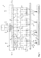
- FIGs 1 to 3 show one out of a total of eight Drying units 1-8 existing dryer line 9. How the individual can be seen from FIG Drying units 1-8 in pairs in groups 10, 11, 12, 13 interconnected.
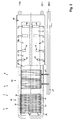
- Figure 2 illustrates the Construction of a drying unit 1-8.
- a trigger unit is arranged vertically one above the other 14 for dried brown coal TBK, a nozzle base unit 15, a heat exchanger unit 16, a steam fluidized bed dryer unit 17 and a task unit 18 for the wet raw lignite FBK.
- Each heat exchanger unit 16 is vertical by one aligned partition 19 in two vertically aligned Fluidized bed cells 20, 21 divided. With that, dryer street 9 shown here a total of sixteen Fluid bed cells 20, 21.
- a common vapor collection chamber 22 is arranged above the steam fluidized bed dryer units 17 .
- Output side of the steam fluidized bed dryer units 17 are internals 23 in the form of grate floor units 24 intended.
- the grate floor units 24 consist of two Layers of one another and offset from one another Angle profiles 25.
- the internals 23 cause one Pressure loss in the drying units 1-8, so that a Uniformization of the volume flow in all drying units 1-8 is done.
- all drying units 1-8 always almost the same amount of hydro-steam KWD deducted, regardless of how far the individual drying units 1-8 from the location the outlet 26 of the vapor collection chamber 22 are removed.
- the internals 23 take on a cleaning function, entrained dust from your hydro-steam KWD is deposited on them.
- Purified hydro-steam KWD is used as a fluidizing medium WM returned to the system via the nozzle base unit 15. Furthermore, the cleaned and heated hydro steam KWD as heating steam HD for the heat exchanger unit 16 can be used.
- each drying unit becomes 1-8 damp Lignite FBK in a grain size range from 0 to 10 mm fed by the task unit 18.
- the feed unit 18 is carried out from the bunker 27 Wet brown coal fed FBK. Arrived from bunker 27 the wet lignite FBK via four bunker funnels 28-31 in four rotary locks 32-35. These give the wet lignite FBK on four chain scraper conveyors 36-39.
- the rotary valve 32-35 and the chain scraper conveyor 36-39 are in a closed pre-treatment room 40, the drying units above 1-8 the steam collection chamber 22 is arranged.
- the pre-treatment room 40 can be heated so that preheating the FBK wet brown coal can be made.
- the Preheating improves the flow behavior of the wet lignite FBK. Since the pre-treatment room 40 is outside the hydro-steam atmosphere, it can easily also during the operation of the drying system Maintenance or repair purposes.
- the FBK passes through the discharge chutes 41, 42 Steam collection chamber 22 and enters the steam fluidized bed dryer unit 17th
- the wet lignite FBK then falls down against it upward flowing vortex medium WM.
- a vortex medium WM comes the expelled from the FBK wet brown coal and cleaned hydro-steam KWD used.
- the steam fluidized bed dryer unit 17 comprises one Chamber 53 which widens in a trapezoidal shape.
- the cross-sectional expansion will reduce the speed of the hydro-steam flowing upwards KWD reached. This will remove fine grain reduced.
- the heat exchanger unit 16 is arranged below the steam fluidized bed dryer unit 17 below the heat exchanger unit 16 is arranged below the Heat exchanger unit 16 is arranged. Above the Heat exchanger unit 16 passes the brown coal bed into the fluidized bed through the heat exchanger unit 16 continues. The fluidized brown coal then flows through the fluidized bed cells 20, 21.
- Heat exchanger tubes 56, 57 integrated. Every heat exchanger tube 56, 57 has longitudinal tube sections inclined to the horizontal 58, 59 on the vertical pipe sections 60, 61 merge.
- the heat exchanger tubes 56, 57 summarized in a tube sheet 62.
- the steam distribution chamber 63, 64 and the condensate collection chambers 65, 66 each bundle 54, 55 are arranged on the same side.
- Via a steam manifold 67 and the manifold 68 is fed to the steam distribution chambers 63, 64 heating steam HD.
- the condensate K occurs into the condensate collection chambers 65, 66 and is about deductions 69, 70 removed.
- Each heat exchanger unit 16 is separated by a partition 19 divided into two fluidized bed cells 20, 21.
- the Partition 19 is penetrated by bundles 54, 55.
- the partition 19 to the cross section of the Heat exchanger tubes 56, 57 provided adapted openings.
- the heat exchanger tubes 56, 57 are through the openings passed through. They are carried by the partition 19 and stabilized.
- a unit from bundles 54, 55, partition 19, tube sheet 62 and steam collecting chambers 63, 64 and condensate collecting chambers 65, 66 can be pre-assembled in the heat exchanger unit 16 can be installed transversely.
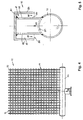
- nozzle base unit 15 there are two grate nozzle bases 71, 72 incorporated. As shown in Figure 4, everyone exists Grate nozzle base 71, 72 from a row parallel and side by side horizontal nozzle pipes 73.
- the grate nozzle bottoms 71, 72 are inserted into the nozzle base unit from one side 15 inserted.
- the loading of the grate nozzle bottoms 71, 72 with vortex medium WM is carried out from the vortex medium ring line 74 from via the feed lines 75, 76 and the Distribution lines 77, 78.
- the vortex medium WM then occurs out through nozzles 79 and flows up through the fluidized bed cells 20, 21.
- FIG. 5 shows the structure of a nozzle 79.
- the nozzle 79 includes a nozzle tube 73 fixed to the vertically upward nozzle 80, which by a Cap 81 is closed. At the top 82 are radial Nozzle openings 83, 84 arranged.
- the vortex medium WM passes through an opening 85 in the nozzle tube 73 in the nozzle 80 and flows through the nozzle openings 83, 84 radially. This is where the vortex medium gets WM in a between socket 80 and cap wall 86 located in the annular space 87. In the annular space 87, the vortex medium WM first flow downwards before crossing the Annular gap 88 can emerge. Through this training the Nozzle 79 is avoided that fine-grained brown coal in the Nozzle openings 83, 84 can flow. This will cause constipation the nozzle tubes 73 prevented.
- hydro-steam KWD as a fluidizing medium WM on the nozzle base unit 15 and the grate nozzle bases 71, 72 initiated. This depends on the pressure overheated with a small temperature difference.
- Hydro-steam KWD flows through the wet lignite FBK on the way through the heat exchanger unit 16 or the fluidized bed cells 20, 21 and the steam fluidized bed dryer unit 17 from bottom to top.
- the lignite to be dried is Hydro-steam KWD in a suspended state transferred.
- the amount of hydro-steam introduced KWD and the inflow speed are designed so that in Area above the heat exchanger unit 16 a homogeneous fluidized bed is created, which is characterized by the heat exchanger unit 16 or the fluidized bed cells 20, 21 continues. There is extraordinary in this flight stream favorable conditions for heat transfer. On the way through the heat exchanger unit 16 is from the downward flowing brown coal evaporates hydrocarbon and the water content is reduced to approx. 10% residual moisture.
- the driven hydro-steam KWD of all drying units 1-8 then gets into the steam collection chamber 22 and from there via outlet 26 for aftertreatment.
- Excess steam can flow from the circulatory system to the Balance the mass balance to be taken to the pressure to keep constant in the drying units 1-8.
- Excess steam can be used as heating steam HD or otherwise will.
- a trigger unit 14 is two Drying units 1, 2; 3, 4; 5, 6; 7, 8 assigned.
- the withdrawal takes place via a screw conveyor 89 with two oppositely aligned spiral sections 90, 91 and a rotary valve 92.
- the side walls 93, 94 of the trigger unit 14 are in the direction of the screw conveyor 89 inclined so that the dried brown coal TBK easily can flow to the screw conveyor 89.
- the cellular wheel locks 92 of the individual extraction units 14 carry the dry lignite TBK on a discharge conveyor 95 from where the dry brown coal TBK to Further use in the power plant process is brought.
- a discharge conveyor 95 extends below the drying units 1-8 in an encapsulated discharge space 96, which, if necessary, for inerting and / or cooling the Dry lignite TBK can be used.
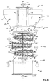
- the drying unit 101 consists of functionally coordinated Modules with trigger unit 102, nozzle base unit 103, heat exchanger unit 104, steam fluidized bed dryer unit 105 and task unit 106.
- drying units 101 are in turn one Lignite drying plant interconnected.
- the too drying amount of wet brown coal for a power plant is divided into several drying units 101.
- All drying units 101 have a common steam collecting chamber 107 above the steam fluidized bed dryer unit 105 assigned. Are in the transition area flow-comparing internals 108 provided to to generate a pressure loss in the drying units 101.
- the heat exchanger unit 104 comprises three one above the other lying bundles 109, 110, 111 configured in a V-shape Heat exchanger tubes 112. Are on the inlet and outlet side the heat exchanger tubes 112 of each bundle 109, 110, 111 in summarized a tube sheet 113. Furthermore, the heat exchanger tubes 112 in, a support structure 114 horizontally aligned support beam 115 and vertical Support structures 116 arranged. Steam distribution chamber 117 and Condensate collection chamber 118 of each bundle 109, 110, 111 are arranged on the same side. Two on top of each other lying bundles 109, 110 and 110, 111 are mutually offset by 180 °.
- the heat exchanger unit 104 is separated by partitions 119 divided into two fluidized bed cells 120, 121.
- the Partitions 119 are of the heat exchanger tubes 112 of the Bundles 109, 110, 111 interspersed.
- lignite FBK is used by the feed unit 106 via a rotary valve 122 and a screw conveyor 123 fed. Via the feed chutes 124, 125 the wet lignite FBK gets into the steam fluidized bed dryer unit 105 and goes into the fluidized bed here about. The wet lignite FBK flows downwards the upward flowing fluidizing medium WM through the fluidized bed cells 121, 122. In this way the hydro expelled.
- the outer walls 128, 129 heatable.
- heating coils for this 130, 131 laid on the outer walls 128, 129 the overview in the present embodiment for the sake of it, however, are only indicated.
- the deduction unit too and the feed unit can be designed to be heatable.
- the extraction of the dried lignite TBK for further use takes place via the trigger unit 102.
Landscapes
- Engineering & Computer Science (AREA)
- Life Sciences & Earth Sciences (AREA)
- Microbiology (AREA)
- Mechanical Engineering (AREA)
- General Engineering & Computer Science (AREA)
- Drying Of Solid Materials (AREA)
Priority Applications (3)
| Application Number | Priority Date | Filing Date | Title |
|---|---|---|---|
| EP96118517A EP0819901A1 (fr) | 1996-07-17 | 1996-11-19 | Installation de séchage de lignite |
| EP97105735A EP0819904A1 (fr) | 1996-07-17 | 1997-04-08 | Installation de séchage à vapeur à lit fluidisé |
| EP97105736A EP0819902A1 (fr) | 1996-07-17 | 1997-04-08 | Installation de séchage à vapeur à lit fluidisé |
Applications Claiming Priority (3)
| Application Number | Priority Date | Filing Date | Title |
|---|---|---|---|
| EP96111495A EP0819900A1 (fr) | 1996-07-17 | 1996-07-17 | Installation pour le séchage à lit fluidisé par vapeur de lignite brut |
| EP96111495 | 1996-07-17 | ||
| EP96118517A EP0819901A1 (fr) | 1996-07-17 | 1996-11-19 | Installation de séchage de lignite |
Publications (1)
| Publication Number | Publication Date |
|---|---|
| EP0819901A1 true EP0819901A1 (fr) | 1998-01-21 |
Family
ID=26142070
Family Applications (1)
| Application Number | Title | Priority Date | Filing Date |
|---|---|---|---|
| EP96118517A Withdrawn EP0819901A1 (fr) | 1996-07-17 | 1996-11-19 | Installation de séchage de lignite |
Country Status (1)
| Country | Link |
|---|---|
| EP (1) | EP0819901A1 (fr) |
Cited By (3)
| Publication number | Priority date | Publication date | Assignee | Title |
|---|---|---|---|---|
| WO2001036887A1 (fr) * | 1999-11-15 | 2001-05-25 | Energy Engineering International (Pty) Ltd. | Appareil de lit fluidise |
| CN102519224A (zh) * | 2011-12-12 | 2012-06-27 | 惠生工程(中国)有限公司 | 一种多级固体燃料干燥系统 |
| DE102011000734A1 (de) | 2011-02-15 | 2012-08-16 | Alstom Technology Ltd. | Düsenbodenanordnung für einen Trockner und Verfahren zu dessen Betrieb |
Citations (10)
| Publication number | Priority date | Publication date | Assignee | Title |
|---|---|---|---|---|
| DE598703C (de) * | 1932-07-08 | 1934-06-16 | Gewerkschaft Leonhardt | Verfahren zur Beschickung von Braunkohlentrocknern |
| US2629938A (en) * | 1949-03-03 | 1953-03-03 | Kaiser Aluminium Chem Corp | Method and apparatus for treating solids |
| GB715836A (en) * | 1950-12-13 | 1954-09-22 | Smidth & Co As F L | Improvements relating to heat-exchange processes for heating or cooling powdered material |
| DE1070325B (de) * | 1959-12-03 | Socony Mobil Oil Company, Inc., New York, N. Y. (V. St. A.) | Verfahren und Vorrichtung zum Trocknen von Adsorptionsmitteln | |
| GB2136101A (en) * | 1983-03-11 | 1984-09-12 | Okawara Mfg | Fluidized-bed dryer |
| DD224649A1 (de) | 1984-06-21 | 1985-07-10 | Inst Energetik Zre Leipzig | Verfahren und einrichting zur erzeugung von kohlenstaub |
| DE3724960A1 (de) | 1987-07-28 | 1989-02-09 | Rheinische Braunkohlenw Ag | Verfahren und anlage zum trocknen von feuchten schuettguetern in einem wirbelbett-trockner |
| EP0341347A1 (fr) * | 1988-05-11 | 1989-11-15 | Waagner-Biro Aktiengesellschaft | Dispositif pour chauffage indirect d'un lit fluidisé |
| EP0343407A1 (fr) * | 1988-05-11 | 1989-11-29 | Waagner-Biro Aktiengesellschaft | Dispositif pour introduire la matière à fluidiser dans un lit fluidisé, en particulier une installation de séchage |
| EP0713070A1 (fr) * | 1994-11-21 | 1996-05-22 | Powdering Japan K.K. | Dispositif de lit fluidisé pour le séchage ou le refroidissement de poudre, et procédé de séchage ou de refroidissement de poudre l'utilisant |
-
1996
- 1996-11-19 EP EP96118517A patent/EP0819901A1/fr not_active Withdrawn
Patent Citations (10)
| Publication number | Priority date | Publication date | Assignee | Title |
|---|---|---|---|---|
| DE1070325B (de) * | 1959-12-03 | Socony Mobil Oil Company, Inc., New York, N. Y. (V. St. A.) | Verfahren und Vorrichtung zum Trocknen von Adsorptionsmitteln | |
| DE598703C (de) * | 1932-07-08 | 1934-06-16 | Gewerkschaft Leonhardt | Verfahren zur Beschickung von Braunkohlentrocknern |
| US2629938A (en) * | 1949-03-03 | 1953-03-03 | Kaiser Aluminium Chem Corp | Method and apparatus for treating solids |
| GB715836A (en) * | 1950-12-13 | 1954-09-22 | Smidth & Co As F L | Improvements relating to heat-exchange processes for heating or cooling powdered material |
| GB2136101A (en) * | 1983-03-11 | 1984-09-12 | Okawara Mfg | Fluidized-bed dryer |
| DD224649A1 (de) | 1984-06-21 | 1985-07-10 | Inst Energetik Zre Leipzig | Verfahren und einrichting zur erzeugung von kohlenstaub |
| DE3724960A1 (de) | 1987-07-28 | 1989-02-09 | Rheinische Braunkohlenw Ag | Verfahren und anlage zum trocknen von feuchten schuettguetern in einem wirbelbett-trockner |
| EP0341347A1 (fr) * | 1988-05-11 | 1989-11-15 | Waagner-Biro Aktiengesellschaft | Dispositif pour chauffage indirect d'un lit fluidisé |
| EP0343407A1 (fr) * | 1988-05-11 | 1989-11-29 | Waagner-Biro Aktiengesellschaft | Dispositif pour introduire la matière à fluidiser dans un lit fluidisé, en particulier une installation de séchage |
| EP0713070A1 (fr) * | 1994-11-21 | 1996-05-22 | Powdering Japan K.K. | Dispositif de lit fluidisé pour le séchage ou le refroidissement de poudre, et procédé de séchage ou de refroidissement de poudre l'utilisant |
Cited By (5)
| Publication number | Priority date | Publication date | Assignee | Title |
|---|---|---|---|---|
| WO2001036887A1 (fr) * | 1999-11-15 | 2001-05-25 | Energy Engineering International (Pty) Ltd. | Appareil de lit fluidise |
| DE102011000734A1 (de) | 2011-02-15 | 2012-08-16 | Alstom Technology Ltd. | Düsenbodenanordnung für einen Trockner und Verfahren zu dessen Betrieb |
| WO2012110884A2 (fr) | 2011-02-15 | 2012-08-23 | Alstom Technology Ltd | Agencement inférieur de buses destiné à un séchoir et procédé d'utilisation dudit séchoir |
| US9528762B2 (en) | 2011-02-15 | 2016-12-27 | General Electric Technology Gmbh | Nozzle bottom arrangement for a dryer and a method for operating said dryer |
| CN102519224A (zh) * | 2011-12-12 | 2012-06-27 | 惠生工程(中国)有限公司 | 一种多级固体燃料干燥系统 |
Similar Documents
| Publication | Publication Date | Title |
|---|---|---|
| AT401418B (de) | Verfahren und vorrichtung zur steuerung der funktion eines wirbelschichtreaktors mit zirkulierender wirbelschicht | |
| DE3743115C2 (de) | Anlage zur Gewinnung von Öl, Gas und Nebenprodukten aus Ölschiefer oder anderen mit Kohlenwasserstoffen imprägnierten festen Materialien mittels Pyrolyse und Verfahren zur Durchführung einer solchen Pyrolyse mittels einer solchen Anlage | |
| EP0064617B1 (fr) | Procédé et dispositif pour l'exploitation d'une installation de fours à coke | |
| DE2535306A1 (de) | Verfahren zum zufuehren von kohlenstaub oder aehnlichem zu einer reaktionskammer und vorrichtung zur durchfuehrung dieses verfahrens | |
| DE69519891T2 (de) | Druckwirbelschicht-Feuerung mit integriertem Rezirkulationswärmetauscher | |
| DE3507303A1 (de) | Anlage zur aufbereitung und reinigung verunreinigter gase | |
| DE2628177A1 (de) | Waermetauscher fuer wirbelschichtreaktor | |
| EP0270531B1 (fr) | Reacteur a lit mobile | |
| DE1958885A1 (de) | Einrichtung zur Trocknung und UEberhitzung von Nassdampf in Atomkernkraftwerken | |
| DE2360580B2 (de) | Drehrohrofenanlage fuer feinkoerniges gut, insbesondere portlandzementklinker | |
| EP0819901A1 (fr) | Installation de séchage de lignite | |
| EP0819903A1 (fr) | Installation de séchage de lignite | |
| DE102010032266A1 (de) | Vorrichtung und Verfahren zur Heißgaserzeugung mit integrierter Erhitzung eines Wärmeträgermediums | |
| DE69923771T2 (de) | Anlage zum trocknen von feuchten aus partikeln bestehendem stoff mittels überhitztem dampf | |
| EP0843141B1 (fr) | Dispositif de chargement de charbon pour une installation de séchage de lignite | |
| DE202014011150U1 (de) | System zum Trocknen von teilchenförmigem Material | |
| DE2442122A1 (de) | Pyrolyse-behaelter | |
| EP2352959A1 (fr) | Sechoir en lit fluidise a chauffage indirect | |
| EP0045890B1 (fr) | Foyer à lit fluidisé | |
| EP0819900A1 (fr) | Installation pour le séchage à lit fluidisé par vapeur de lignite brut | |
| EP0157901B1 (fr) | Four à couche fluidisée | |
| DE3721421C2 (fr) | ||
| DE2535683A1 (de) | Verfahren und vorrichtung zur verbrennung von schlaemmen mit hilfe rekuperativer schlammtrocknung | |
| EP0819904A1 (fr) | Installation de séchage à vapeur à lit fluidisé | |
| EP0819902A1 (fr) | Installation de séchage à vapeur à lit fluidisé |
Legal Events
| Date | Code | Title | Description |
|---|---|---|---|
| PUAI | Public reference made under article 153(3) epc to a published international application that has entered the european phase |
Free format text: ORIGINAL CODE: 0009012 |
|
| AK | Designated contracting states |
Kind code of ref document: A1 Designated state(s): AT DE DK FI SE |
|
| AKX | Designation fees paid |
Free format text: AT DE DK FI SE |
|
| RBV | Designated contracting states (corrected) |
Designated state(s): AT DE DK FI SE |
|
| STAA | Information on the status of an ep patent application or granted ep patent |
Free format text: STATUS: THE APPLICATION IS DEEMED TO BE WITHDRAWN |
|
| 18D | Application deemed to be withdrawn |
Effective date: 19980722 |