EP0342836A2 - Vorrichtung zur Strahlvereinigung - Google Patents
Vorrichtung zur Strahlvereinigung Download PDFInfo
- Publication number
- EP0342836A2 EP0342836A2 EP89304611A EP89304611A EP0342836A2 EP 0342836 A2 EP0342836 A2 EP 0342836A2 EP 89304611 A EP89304611 A EP 89304611A EP 89304611 A EP89304611 A EP 89304611A EP 0342836 A2 EP0342836 A2 EP 0342836A2
- Authority
- EP
- European Patent Office
- Prior art keywords
- combining unit
- beams
- collimating lenses
- beam combining
- focusing lens
- Prior art date
- Legal status (The legal status is an assumption and is not a legal conclusion. Google has not performed a legal analysis and makes no representation as to the accuracy of the status listed.)
- Withdrawn
Links
- 230000003287 optical effect Effects 0.000 claims abstract description 23
- 239000000463 material Substances 0.000 abstract description 8
- 239000013307 optical fiber Substances 0.000 description 18
- 238000000429 assembly Methods 0.000 description 13
- 230000000712 assembly Effects 0.000 description 13
- 239000000835 fiber Substances 0.000 description 10
- 239000007789 gas Substances 0.000 description 8
- XLYOFNOQVPJJNP-UHFFFAOYSA-N water Substances O XLYOFNOQVPJJNP-UHFFFAOYSA-N 0.000 description 8
- 238000005520 cutting process Methods 0.000 description 2
- QVGXLLKOCUKJST-UHFFFAOYSA-N atomic oxygen Chemical compound [O] QVGXLLKOCUKJST-UHFFFAOYSA-N 0.000 description 1
- 239000000498 cooling water Substances 0.000 description 1
- 238000010586 diagram Methods 0.000 description 1
- 238000005553 drilling Methods 0.000 description 1
- 238000002474 experimental method Methods 0.000 description 1
- 238000000034 method Methods 0.000 description 1
- 239000001301 oxygen Substances 0.000 description 1
- 229910052760 oxygen Inorganic materials 0.000 description 1
- 238000003466 welding Methods 0.000 description 1
Images


Classifications
-
- B—PERFORMING OPERATIONS; TRANSPORTING
- B23—MACHINE TOOLS; METAL-WORKING NOT OTHERWISE PROVIDED FOR
- B23K—SOLDERING OR UNSOLDERING; WELDING; CLADDING OR PLATING BY SOLDERING OR WELDING; CUTTING BY APPLYING HEAT LOCALLY, e.g. FLAME CUTTING; WORKING BY LASER BEAM
- B23K26/00—Working by laser beam, e.g. welding, cutting or boring
- B23K26/02—Positioning or observing the workpiece, e.g. with respect to the point of impact; Aligning, aiming or focusing the laser beam
- B23K26/06—Shaping the laser beam, e.g. by masks or multi-focusing
- B23K26/0604—Shaping the laser beam, e.g. by masks or multi-focusing by a combination of beams
- B23K26/0613—Shaping the laser beam, e.g. by masks or multi-focusing by a combination of beams having a common axis
-
- B—PERFORMING OPERATIONS; TRANSPORTING
- B23—MACHINE TOOLS; METAL-WORKING NOT OTHERWISE PROVIDED FOR
- B23K—SOLDERING OR UNSOLDERING; WELDING; CLADDING OR PLATING BY SOLDERING OR WELDING; CUTTING BY APPLYING HEAT LOCALLY, e.g. FLAME CUTTING; WORKING BY LASER BEAM
- B23K26/00—Working by laser beam, e.g. welding, cutting or boring
- B23K26/02—Positioning or observing the workpiece, e.g. with respect to the point of impact; Aligning, aiming or focusing the laser beam
- B23K26/06—Shaping the laser beam, e.g. by masks or multi-focusing
- B23K26/0604—Shaping the laser beam, e.g. by masks or multi-focusing by a combination of beams
-
- B—PERFORMING OPERATIONS; TRANSPORTING
- B23—MACHINE TOOLS; METAL-WORKING NOT OTHERWISE PROVIDED FOR
- B23K—SOLDERING OR UNSOLDERING; WELDING; CLADDING OR PLATING BY SOLDERING OR WELDING; CUTTING BY APPLYING HEAT LOCALLY, e.g. FLAME CUTTING; WORKING BY LASER BEAM
- B23K26/00—Working by laser beam, e.g. welding, cutting or boring
- B23K26/02—Positioning or observing the workpiece, e.g. with respect to the point of impact; Aligning, aiming or focusing the laser beam
- B23K26/06—Shaping the laser beam, e.g. by masks or multi-focusing
- B23K26/064—Shaping the laser beam, e.g. by masks or multi-focusing by means of optical elements, e.g. lenses, mirrors or prisms
- B23K26/0648—Shaping the laser beam, e.g. by masks or multi-focusing by means of optical elements, e.g. lenses, mirrors or prisms comprising lenses
-
- B—PERFORMING OPERATIONS; TRANSPORTING
- B23—MACHINE TOOLS; METAL-WORKING NOT OTHERWISE PROVIDED FOR
- B23K—SOLDERING OR UNSOLDERING; WELDING; CLADDING OR PLATING BY SOLDERING OR WELDING; CUTTING BY APPLYING HEAT LOCALLY, e.g. FLAME CUTTING; WORKING BY LASER BEAM
- B23K26/00—Working by laser beam, e.g. welding, cutting or boring
- B23K26/02—Positioning or observing the workpiece, e.g. with respect to the point of impact; Aligning, aiming or focusing the laser beam
- B23K26/06—Shaping the laser beam, e.g. by masks or multi-focusing
- B23K26/0665—Shaping the laser beam, e.g. by masks or multi-focusing by beam condensation on the workpiece, e.g. for focusing
-
- G—PHYSICS
- G02—OPTICS
- G02B—OPTICAL ELEMENTS, SYSTEMS OR APPARATUS
- G02B27/00—Optical systems or apparatus not provided for by any of the groups G02B1/00 - G02B26/00, G02B30/00
- G02B27/10—Beam splitting or combining systems
- G02B27/12—Beam splitting or combining systems operating by refraction only
- G02B27/123—The splitting element being a lens or a system of lenses, including arrays and surfaces with refractive power
-
- G—PHYSICS
- G02—OPTICS
- G02B—OPTICAL ELEMENTS, SYSTEMS OR APPARATUS
- G02B6/00—Light guides; Structural details of arrangements comprising light guides and other optical elements, e.g. couplings
- G02B6/24—Coupling light guides
- G02B6/26—Optical coupling means
- G02B6/28—Optical coupling means having data bus means, i.e. plural waveguides interconnected and providing an inherently bidirectional system by mixing and splitting signals
- G02B6/2804—Optical coupling means having data bus means, i.e. plural waveguides interconnected and providing an inherently bidirectional system by mixing and splitting signals forming multipart couplers without wavelength selective elements, e.g. "T" couplers, star couplers
- G02B6/2848—Optical coupling means having data bus means, i.e. plural waveguides interconnected and providing an inherently bidirectional system by mixing and splitting signals forming multipart couplers without wavelength selective elements, e.g. "T" couplers, star couplers having refractive means, e.g. imaging elements between light guides as splitting, branching and/or combining devices, e.g. lenses, holograms
-
- G—PHYSICS
- G02—OPTICS
- G02B—OPTICAL ELEMENTS, SYSTEMS OR APPARATUS
- G02B6/00—Light guides; Structural details of arrangements comprising light guides and other optical elements, e.g. couplings
- G02B6/24—Coupling light guides
- G02B6/42—Coupling light guides with opto-electronic elements
- G02B6/4201—Packages, e.g. shape, construction, internal or external details
- G02B6/4249—Packages, e.g. shape, construction, internal or external details comprising arrays of active devices and fibres
-
- G—PHYSICS
- G02—OPTICS
- G02B—OPTICAL ELEMENTS, SYSTEMS OR APPARATUS
- G02B6/00—Light guides; Structural details of arrangements comprising light guides and other optical elements, e.g. couplings
- G02B6/24—Coupling light guides
- G02B6/42—Coupling light guides with opto-electronic elements
- G02B6/4296—Coupling light guides with opto-electronic elements coupling with sources of high radiant energy, e.g. high power lasers, high temperature light sources
-
- Y—GENERAL TAGGING OF NEW TECHNOLOGICAL DEVELOPMENTS; GENERAL TAGGING OF CROSS-SECTIONAL TECHNOLOGIES SPANNING OVER SEVERAL SECTIONS OF THE IPC; TECHNICAL SUBJECTS COVERED BY FORMER USPC CROSS-REFERENCE ART COLLECTIONS [XRACs] AND DIGESTS
- Y02—TECHNOLOGIES OR APPLICATIONS FOR MITIGATION OR ADAPTATION AGAINST CLIMATE CHANGE
- Y02E—REDUCTION OF GREENHOUSE GAS [GHG] EMISSIONS, RELATED TO ENERGY GENERATION, TRANSMISSION OR DISTRIBUTION
- Y02E30/00—Energy generation of nuclear origin
- Y02E30/10—Nuclear fusion reactors
Definitions
- This invention relates to a beam combining unit, and also to a laser system in which the beams from a plurality of lasers are combined.
- a beam combining unit for combining the output beams of a plurality of lasers after the beams have been transmitted along optical fibres, said beam combining unit comprising a single focusing lens, a plurality of collimating lenses each of which is spaced from the focusing lens on one side thereof, and a holding means located on the opposite side of the collimating lenses from the focusing lens for receiving the ends of a plurality of optical fibres, the focusing lens, the collimating lenses and the holding means being arranged so that, in use, laser beams transmitted along the optical fibres are directed by the collimating lenses, as collimated beams, onto the focusing lens with the axes of the individual beams parallel to each other.
- the beam combining unit of the first aspect of this invention is capable of combining the beams from a number of individual lasers after the beams have been transmitted along optical fibres so that the beams are focused to a common point.
- a laser system comprising a plurality of individual lasers, a beam combining unit according to the first aspect of this invention, a plurality of optical fibres each of which has one end received by the beam combining unit, and a plurality of optical devices each of which focuses the output beam from a respective laser onto the other end of a respective one of said optical fibres.
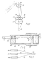
- a beam combining unit 10 which combines the output beams from three flexible optical fibre assemblies 11, 12, 13 and focuses them to a common point 14.
- the optical fibre assemblies are received at positions which are circularly spaced relative to each other at 120° intervals.
- the diverging beam from each of the optical fibre assemblies 11, 12, 13 is collimated by an associated one of a set of collimating lenses 14, 15, 16, which are circularly spaced from each other at 120° intervals.
- the resulting parallel beams from the collimating lenses 14, 15, 16 are then focused by a single focusing lens 17 to the common point 14.
- the focusing lens 17 is the only optical component which is subjected to the combined power of all three laser beams.
- the beam combining unit 10 is shown in more detail in Fig. 2. As shown there, the unit 10 comprises a holder member 20, a tubular member 21, and a head member 22, the holder member 20 being received in one end of the tubular member 21 and the other end of tubular member 21 being received in head 22.
- holder member 20 there are formed three stepped cylindrical bores, only one of which is shown in Fig. 2, and each of these bores receives a connector mounted on the end of an associated optical fibre assembly.
- Fig. 2 there is shown a connector 24 mounted on the end of fibre assembly 11 and received in a bore 23.
- the three bores are arranged in a common plane and spaced circularly relative to each other at 120° intervals.
- each of the collimating lenses comprises a single plano-convex lens element. These bores are arranged so that the collimating lenses 14, 15, 16 lie in a common plane with their axes spaced circularly relative to each other at 120° intervals. Each of the collimating lenses 14, 15, 16 is co-axial with its associated one of the bores in the holder member 20.
- the three stepped cylindrical bores in head member 22 lead to a single cylindrical bore 26 containing a lens mount 27 for the focusing lens 17.
- the focusing lens 17 comprises a two element achromatic lens.
- the axis of the focusing lens 17 is parallel to the axis of the three collimating lenses 14, 15, 16.
- a laser system which comprises three individual lasers 30, 31, and 32.
- the output beam from each of the lasers 30, 31, 32 is focused by a focusing lens, not shown, onto one end of a respective one of the optical fibre assemblies 11, 12, 13.
- the other end of each of the fibre assemblies 11, 12, 13 is connected to the beam combining unit 10.
- the output from all three lasers 30, 31, 32 may be combined and focused to a single point.
- the fibre optic delivery system comprising the fibre assemblies 11, 12, 13 together with the beam combining unit 10
- the combined output from the three lasers may be readily delivered to a desired location to perform a material processing operation.
- Each of the lasers 30, 31, 32 may be, for example, a JK 701 Nd-YAG laser supplied by Lumonics Limited, Rugby, England. Each of these lasers produces a beam having an mean output power of 400W. In an experiment using three such lasers together with the beam combining unit as shown in Figs. 1 and 2, the power delivered to the focus point was found to be about 1 kW.
- the individual pulses may be combined in various ways, three such ways being illustrated in Figs. 4a, 4b, 4c.
- the pulses from the individual lasers may be delivered simultaneously, thereby achieving the same output frequency as that delivered by the individual lasers but with a pulse energy nearly three times greater than the pulse energy from each individual laser.
- the individual pulses may be interleaved so that each pulse has nearly the same energy as the pulses from the individual lasers but with an output repetition rate three times greater than the repetition rate from the individual lasers.
- Fig. 4c by broadening the pulse durations, a continuous wave output may be obtained.
- the laser system shown in Fig. 3 is suitable for various types of material processing operations, such as drilling, welding, and cutting.
- the lens combining unit may be readily modified to combine only two laser beams or more than three, for example, 7 or 20 laser beams.
- 7 laser beams this may be achieved by using seven discrete collimating lenses, with one of the collimating lenses occupying a central position and the other six collimating lenses spaced around the central lens at equally spaced circumferential intervals.
- the discrete collimating lenses may be replaced by a single lenticular element providing the required number of individual lenses.
- the lens combining unit 10 may readily be modified so that the ends of the fibre assemblies or collimating lenses or both of these are staggered relative to each other.
- each collimating lens should be spaced from the end of its associated fibre assembly by a distance equal to the focal length of the lens.
- Each of the collimating lenses 14, 15, 16 and the focusing lens 17 may be formed either from a single lens element or from a set of lens elements.
- the term "lens” is to be interpreted as covering a single lens element or a set of lens elements or, more generally, a lens formed from a set of individual components.
- the beam combining units described above may be used so that the common focus point of the beam combining unit corresponds to the point at which a desired material processing operation is to be performed.
- the beam combining units may be used to couple the laser beams directly, or indirectly, into a single fibre assembly.
- the input face of the single fibre assembly may be located at the common focus point.
- FIG 5 there is shown a longitudinal sectional view of another beam combining unit 40 embodying this invention.
- the beam combining unit 40 combines the output beams from three optical fibre assemblies and focuses them to a single point for performing a material processing operation.
- this optical fibre assembly is indicated by reference numeral 41.
- the parts of the beam combining unit 40 associated with the other two optical fibre assemblies and also certain other parts are omitted from Figure 5.
- the optical fibre assembly 41 comprises an optical fibre 42 guided in a conduit 43.
- the beam combining unit 40 includes a first holder member 45, a second holder member 46, a head assembly 47 and a nozzle assembly 48.
- the second holder member 46 is connected to the head assembly by a tubular member 49.
- the first and second holder members 45,46 are connected together by a gas pipe 51 and an inlet water pipe and an outlet water pipe, not shown.
- the gas pipe 51 has an inlet to the left of the first holder member 45.
- the water pipes are provided, respectively, with an inlet and an outlet to the left of the first holder member 45.
- the three pipes are circularly spaced relative to each other at intervals of 120°.
- a cover 52 extends around the three pipes and between the first and second holder members 45, 46.
- the optical fibre assembly 41 is received in a connector assembly 55 mounted in a bore formed in the first holder member 45.
- the end of the conduit 43 is held in the connector assembly 55 but the optical fibre 42 passes through the first holder member 45 and its end is held in a support member 56 by grub screws, not shown.
- the grub screws permit the position of the end of the optical fibre 42 to be adjusted axially.
- a mounting member 57 having a conical light passage 58 is mounted in a bore in the second holder member 46.
- a mounting ring 59 is secured to the mounting member 58.
- the right hand end of the support member 56 engages the left hand face of the mounting member 57 and the support member 56 is held in position by grub screws, not shown, extending radially inwards from the mounting ring 59.
- the grub screws permit the position of the support member 56, and hence the end of the optical fibre 42, to be adjusted laterally.
- the other two optical fibre assemblies are received in a similar manner.
- the ends of all three optical fibres lie substantially in a common plane and are circularly spaced at 120° intervals.
- An annular lens mount 61 is engaged with the inner surface of tubular member 49.
- the lens mount 61 holds a collimating lens 62 associated with the optical fibre 42 and also two other collimating lenses, not shown, associated with the other two optical fibres.
- a collimating lens 62 associated with the optical fibre 42 and also two other collimating lenses, not shown, associated with the other two optical fibres.
- Figure 5 only the part of lens mount 61 associated with lens 62 is shown.
- the three collimating lenses lie in a common plane and their axes are circularly spaced at intervals of 120°.
- the head assembly 47 includes a lens mount 64 for a single convex focusing lens 65.
- the lens 65 is held in place by a mounting ring 66.
- the axis of lens 65 and the axes of the three collimating lenses are substantially parallel to each other.
- a protection slide 67 is mounted in head assembly 47.
- the head assembly 47 also includes a support member 70 for the nozzle assembly 48.
- the nozzle assembly 48 has a substantially conical light transmitting passage 71 which terminates in an outlet aperture 72.
- a gas passage 75 is formed in the tubular member 49. One end of gas passage 75 communicates with the gas pipe 51 and the other end communicates with the inside of nozzle assembly 48.
- a pair of water passages are formed in the tubular member 49 and one of these is shown and indicated by reference number 76. These two water passages communicate with the two water pipes mentioned earlier.
- a system of conduits is provided in the second holder member 46, the tubular member 49 and the head assembly 47. These conduits cause cooling water, which enters through the inlet water pipe, to flow around the support member 57, the lens mount 61 and the focusing lens 65 before leaving through the outlet water pipe.
- the beam combining unit 40 may receive the output beams from three lasers via three optical fibre assemblies in a manner similar to that described with reference to Figure 3.
- the position of the ends of the three optical fibres are adjusted accurately so that the three collimating lenses direct three collimated and mutually parallel beams onto the focusing lens 65.
- the focusing lens 65 focuses the three beams to a common point just outside the outlet aperture 72.
- the beam combining unit 40 may be held in a robotic device and manipulated so as to perform a desired material processing operation.
- a gas may be supplied through gas pipe 51 so that the material processing operation is performed in an atmosphere which assists that operation.
- the assisting gas may be oxygen.
Landscapes
- Physics & Mathematics (AREA)
- Optics & Photonics (AREA)
- Engineering & Computer Science (AREA)
- Plasma & Fusion (AREA)
- Mechanical Engineering (AREA)
- General Physics & Mathematics (AREA)
- Laser Beam Processing (AREA)
- Optical Couplings Of Light Guides (AREA)
Applications Claiming Priority (2)
| Application Number | Priority Date | Filing Date | Title |
|---|---|---|---|
| GB8811532 | 1988-05-16 | ||
| GB888811532A GB8811532D0 (en) | 1988-05-16 | 1988-05-16 | Beam combining unit |
Publications (2)
| Publication Number | Publication Date |
|---|---|
| EP0342836A2 true EP0342836A2 (de) | 1989-11-23 |
| EP0342836A3 EP0342836A3 (de) | 1990-04-11 |
Family
ID=10636967
Family Applications (1)
| Application Number | Title | Priority Date | Filing Date |
|---|---|---|---|
| EP89304611A Withdrawn EP0342836A3 (de) | 1988-05-16 | 1989-05-08 | Vorrichtung zur Strahlvereinigung |
Country Status (4)
| Country | Link |
|---|---|
| US (1) | US5029964A (de) |
| EP (1) | EP0342836A3 (de) |
| JP (1) | JPH0250105A (de) |
| GB (1) | GB8811532D0 (de) |
Cited By (3)
| Publication number | Priority date | Publication date | Assignee | Title |
|---|---|---|---|---|
| EP0676653A1 (de) * | 1994-04-11 | 1995-10-11 | Mitsui Petrochemical Industries, Ltd. | Optischer Faserkoppler |
| EP1166948A3 (de) * | 2000-06-09 | 2002-07-10 | Sumitomo Heavy Industries, Ltd. | Vorrichtung und Verfahren zur Laserbehandlung |
| CN117381212A (zh) * | 2023-11-23 | 2024-01-12 | 江阴创可激光技术有限公司 | 一种双激光器出光的激光加工装置 |
Families Citing this family (27)
| Publication number | Priority date | Publication date | Assignee | Title |
|---|---|---|---|---|
| DE69130854T2 (de) * | 1990-11-21 | 1999-08-05 | Canon K.K., Tokio/Tokyo | Laserbearbeitungsgerät |
| ATE155933T1 (de) * | 1992-05-06 | 1997-08-15 | Electrox Ltd | System zum kombinieren von laserstrahlen |
| US5430816A (en) * | 1992-10-27 | 1995-07-04 | Matsushita Electric Industrial Co., Ltd. | Multiple split-beam laser processing apparatus generating an array of focused beams |
| WO1995031633A1 (en) * | 1994-05-13 | 1995-11-23 | Nippondenso Co., Ltd. | Vane type rotary phase regulator |
| US6006709A (en) * | 1995-06-14 | 1999-12-28 | Nippondenso Co., Ltd. | Control apparatus for varying a rotational or angular phase between two rotational shafts, preferably applicable to a valve timing control apparatus for an internal combustion engine |
| US5823152A (en) | 1995-06-14 | 1998-10-20 | Nippondenso Co., Ltd. | Control apparatus for varying a rotational or angular phase between two rotational shafts, preferably applicable to a valve timing control apparatus for an internal combustion engine |
| DE69606613T2 (de) * | 1995-11-30 | 2000-07-13 | Aisin Seiki K.K., Kariya | Ventilzeitsteuerungsvorrichtung |
| US5836276A (en) * | 1996-08-09 | 1998-11-17 | Denso Corporation | Rotational phase adjusting apparatus having fluid reservoir |
| DE19740215B4 (de) * | 1996-09-13 | 2006-02-09 | Denso Corp., Kariya | Drehphaseneinstellvorrichtung mit einer Kunstharzdichtung |
| JP3262207B2 (ja) * | 1996-10-02 | 2002-03-04 | 株式会社デンソー | 内燃機関用バルブタイミング調整装置 |
| JP3116858B2 (ja) * | 1996-11-29 | 2000-12-11 | トヨタ自動車株式会社 | 内燃機関のバルブタイミング可変機構 |
| US5836277A (en) * | 1996-12-24 | 1998-11-17 | Aisin Seiki Kabushiki Kaisha | Valve timing control device |
| JP4202440B2 (ja) * | 1997-02-06 | 2008-12-24 | アイシン精機株式会社 | 弁開閉時期制御装置 |
| JP3823451B2 (ja) * | 1997-06-24 | 2006-09-20 | アイシン精機株式会社 | 弁開閉時期制御装置 |
| JP3824110B2 (ja) * | 1997-06-30 | 2006-09-20 | アイシン精機株式会社 | 弁開閉時期制御装置 |
| US6173687B1 (en) | 1997-11-14 | 2001-01-16 | Mitsubishi Denki Kabushiki Kaisha | Hydraulic apparatus for adjusting the timing of opening and closing of an engine valve |
| JP3815014B2 (ja) * | 1997-12-24 | 2006-08-30 | アイシン精機株式会社 | 弁開閉時期制御装置 |
| KR100921964B1 (ko) * | 2007-12-14 | 2009-10-15 | 한국기초과학지원연구원 | 플라즈마 상태 모니터링 시스템 |
| US8509272B2 (en) | 2009-06-10 | 2013-08-13 | Lee Laser, Inc. | Laser beam combining and power scaling device |
| US20110063701A1 (en) * | 2009-09-14 | 2011-03-17 | Nano-optic Device, LLC | Digital optical, planar holography system and method for improving brightness of light beams |
| JP5136628B2 (ja) | 2010-01-20 | 2013-02-06 | 株式会社デンソー | バルブタイミング調整装置 |
| WO2012157355A1 (ja) * | 2011-05-19 | 2012-11-22 | 村田機械株式会社 | レーザ加工機 |
| JP5938622B2 (ja) * | 2011-12-28 | 2016-06-22 | 株式会社村谷機械製作所 | レーザ加工装置及びレーザ加工方法 |
| JP6495059B2 (ja) | 2015-03-18 | 2019-04-03 | 三菱重工業株式会社 | レーザアレイデバイス |
| DE102015005246A1 (de) | 2015-04-24 | 2016-10-27 | Alpha Laser Gmbh | Fokussierobjektiv mit flexibler Fokusverschiebung, veränderbarem Strahlprofil und Hochsicherheits-Laserstrahlfänger |
| CN106199857A (zh) * | 2016-07-28 | 2016-12-07 | 福建福晶科技股份有限公司 | 一种高功率光纤准直聚焦镜 |
| CN115877580B (zh) * | 2022-12-02 | 2025-11-25 | 北京理工大学 | 一种连续表面光纤激光准直合束装置 |
Family Cites Families (16)
| Publication number | Priority date | Publication date | Assignee | Title |
|---|---|---|---|---|
| US3513306A (en) * | 1967-07-24 | 1970-05-19 | Trw Inc | Multimodular collimated light projection system |
| US3518419A (en) * | 1967-12-28 | 1970-06-30 | Us Army | Projection system for circular array of laser diodes |
| US3588440A (en) * | 1969-06-26 | 1971-06-28 | Hughes Aircraft Co | Laser combination energy system |
| US3743383A (en) * | 1972-03-23 | 1973-07-03 | Us Navy | High power beam combiner |
| US3802767A (en) * | 1972-07-03 | 1974-04-09 | Raytheon Co | Catoptric lens arrangement |
| JPS53136848A (en) * | 1977-05-04 | 1978-11-29 | Matsushita Electric Ind Co Ltd | Optical branching device |
| US4185891A (en) * | 1977-11-30 | 1980-01-29 | Grumman Aerospace Corporation | Laser diode collimation optics |
| US4289378A (en) * | 1978-06-21 | 1981-09-15 | Ernst Remy | Apparatus for adjusting the focal point of an operating laser beam focused by an objective |
| US4344671A (en) * | 1979-12-17 | 1982-08-17 | Raymus K. Payton | Multiple pulse laser assemblies |
| JPS5969979A (ja) * | 1982-10-15 | 1984-04-20 | Hitachi Ltd | レ−ザ光源装置 |
| JPS59200211A (ja) * | 1983-04-28 | 1984-11-13 | Mitsubishi Electric Corp | 光多分岐装置 |
| IT1182328B (it) * | 1984-12-19 | 1987-10-05 | Cselt Centro Studi Lab Telecom | Accoppiatore per fibre ottiche |
| JPS62124209A (ja) * | 1985-11-21 | 1987-06-05 | Kawasaki Steel Corp | 炉内測定方法 |
| US4705351A (en) * | 1985-11-26 | 1987-11-10 | Rca Corporation | Two lens optical package and method of making same |
| US4868361A (en) * | 1988-04-01 | 1989-09-19 | General Electric Company | Coupling device for high power laser beam transmitting optical fibers |
| US4844574A (en) * | 1988-07-05 | 1989-07-04 | General Electric Company | Optical fiber output coupler for a power laser |
-
1988
- 1988-05-16 GB GB888811532A patent/GB8811532D0/en active Pending
-
1989
- 1989-05-08 EP EP89304611A patent/EP0342836A3/de not_active Withdrawn
- 1989-05-10 US US07/350,663 patent/US5029964A/en not_active Expired - Fee Related
- 1989-05-16 JP JP1120588A patent/JPH0250105A/ja active Pending
Cited By (7)
| Publication number | Priority date | Publication date | Assignee | Title |
|---|---|---|---|---|
| EP0676653A1 (de) * | 1994-04-11 | 1995-10-11 | Mitsui Petrochemical Industries, Ltd. | Optischer Faserkoppler |
| US5633967A (en) * | 1994-04-11 | 1997-05-27 | Mitsui Petrochemical Industries, Ltd. | Waveguide fiber optical coupler |
| EP1166948A3 (de) * | 2000-06-09 | 2002-07-10 | Sumitomo Heavy Industries, Ltd. | Vorrichtung und Verfahren zur Laserbehandlung |
| US6580055B2 (en) * | 2000-06-09 | 2003-06-17 | Sumitomo Heavy Industries, Ltd. | Laser processing apparatus and method |
| US6710289B2 (en) | 2000-06-09 | 2004-03-23 | Sumitomo Heavy Industries, Ltd. | Laser processing apparatus and method |
| CN117381212A (zh) * | 2023-11-23 | 2024-01-12 | 江阴创可激光技术有限公司 | 一种双激光器出光的激光加工装置 |
| CN117381212B (zh) * | 2023-11-23 | 2024-05-10 | 江阴创可激光技术有限公司 | 一种双激光器出光的激光加工装置 |
Also Published As
| Publication number | Publication date |
|---|---|
| JPH0250105A (ja) | 1990-02-20 |
| US5029964A (en) | 1991-07-09 |
| GB8811532D0 (en) | 1988-06-22 |
| EP0342836A3 (de) | 1990-04-11 |
Similar Documents
| Publication | Publication Date | Title |
|---|---|---|
| EP0342836A2 (de) | Vorrichtung zur Strahlvereinigung | |
| USRE40173E1 (en) | High efficiency, high power direct diode laser systems and methods therefor | |
| US4707073A (en) | Fiber optic beam delivery system for high-power laser | |
| US4844574A (en) | Optical fiber output coupler for a power laser | |
| US4799755A (en) | Laser materials processing with a lensless fiber optic output coupler | |
| US5179610A (en) | Connector for coupling of laser energy | |
| US4676586A (en) | Apparatus and method for performing laser material processing through a fiber optic | |
| EP4183513A1 (de) | Multimode-lasergerät für anwendungen in der metallbearbeitung | |
| US5633967A (en) | Waveguide fiber optical coupler | |
| GB2236973A (en) | Producing high-precision through bores by laser radiation | |
| JPH02284783A (ja) | ホルダ | |
| US11287574B2 (en) | Optical fiber bundle with beam overlapping mechanism | |
| US5054877A (en) | Multi-fiber optical coupler for a high power laser beam | |
| GB2298607A (en) | Laser beam machines | |
| US11453084B2 (en) | Laser processing head for laser-wire build-up welding | |
| GB2288906A (en) | Axially pumped laser incorporating target visible laser beam | |
| US4795227A (en) | Beam splitting fiber optic coupler | |
| KR102675028B1 (ko) | 접근하기 어려운 공작물의 레이저 가공장치 | |
| US5289553A (en) | Lens holding system for fiber optic output couplers | |
| JP2000517435A (ja) | 光伝達装置 | |
| JPH10314973A (ja) | 複合レーザビームによるレーザ加工装置および加工法 | |
| CN116833495A (zh) | 拓扑解耦的激光环绕电解液式复合加工用工具系统 | |
| US5991015A (en) | Beam monitoring assembly | |
| CN213570743U (zh) | 矩形匀化光斑激光熔覆头 | |
| Koga et al. | Development of a portable laser sheet |
Legal Events
| Date | Code | Title | Description |
|---|---|---|---|
| PUAI | Public reference made under article 153(3) epc to a published international application that has entered the european phase |
Free format text: ORIGINAL CODE: 0009012 |
|
| AK | Designated contracting states |
Kind code of ref document: A2 Designated state(s): CH DE FR GB IT LI NL SE |
|
| PUAL | Search report despatched |
Free format text: ORIGINAL CODE: 0009013 |
|
| AK | Designated contracting states |
Kind code of ref document: A3 Designated state(s): CH DE FR GB IT LI NL SE |
|
| RIN1 | Information on inventor provided before grant (corrected) |
Inventor name: WITHNALL, KEITH Inventor name: EDWARDS, GLYN RICHARD |
|
| 17P | Request for examination filed |
Effective date: 19901002 |
|
| STAA | Information on the status of an ep patent application or granted ep patent |
Free format text: STATUS: THE APPLICATION HAS BEEN WITHDRAWN |
|
| 18W | Application withdrawn |
Withdrawal date: 19911016 |