EP0342807B1 - Filterelement - Google Patents
Filterelement Download PDFInfo
- Publication number
- EP0342807B1 EP0342807B1 EP89304287A EP89304287A EP0342807B1 EP 0342807 B1 EP0342807 B1 EP 0342807B1 EP 89304287 A EP89304287 A EP 89304287A EP 89304287 A EP89304287 A EP 89304287A EP 0342807 B1 EP0342807 B1 EP 0342807B1
- Authority
- EP
- European Patent Office
- Prior art keywords
- filter element
- filter
- pressure drop
- web
- rear walls
- Prior art date
- Legal status (The legal status is an assumption and is not a legal conclusion. Google has not performed a legal analysis and makes no representation as to the accuracy of the status listed.)
- Expired - Lifetime
Links
Images

Classifications
-
- A—HUMAN NECESSITIES
- A62—LIFE-SAVING; FIRE-FIGHTING
- A62B—DEVICES, APPARATUS OR METHODS FOR LIFE-SAVING
- A62B18/00—Breathing masks or helmets, e.g. affording protection against chemical agents or for use at high altitudes or incorporating a pump or compressor for reducing the inhalation effort
-
- A—HUMAN NECESSITIES
- A62—LIFE-SAVING; FIRE-FIGHTING
- A62B—DEVICES, APPARATUS OR METHODS FOR LIFE-SAVING
- A62B23/00—Filters for breathing-protection purposes
- A62B23/02—Filters for breathing-protection purposes for respirators
-
- A—HUMAN NECESSITIES
- A62—LIFE-SAVING; FIRE-FIGHTING
- A62B—DEVICES, APPARATUS OR METHODS FOR LIFE-SAVING
- A62B18/00—Breathing masks or helmets, e.g. affording protection against chemical agents or for use at high altitudes or incorporating a pump or compressor for reducing the inhalation effort
- A62B18/08—Component parts for gas-masks or gas-helmets, e.g. windows, straps, speech transmitters, signal-devices
-
- Y—GENERAL TAGGING OF NEW TECHNOLOGICAL DEVELOPMENTS; GENERAL TAGGING OF CROSS-SECTIONAL TECHNOLOGIES SPANNING OVER SEVERAL SECTIONS OF THE IPC; TECHNICAL SUBJECTS COVERED BY FORMER USPC CROSS-REFERENCE ART COLLECTIONS [XRACs] AND DIGESTS
- Y10—TECHNICAL SUBJECTS COVERED BY FORMER USPC
- Y10S—TECHNICAL SUBJECTS COVERED BY FORMER USPC CROSS-REFERENCE ART COLLECTIONS [XRACs] AND DIGESTS
- Y10S55/00—Gas separation
- Y10S55/35—Respirators and register filters
Definitions
- the present invention relates to filtration elements used in respirators or face masks. In another aspect, the present invention relates to filtration face masks or respirators with detachable filtration elements.
- Filtration face masks or respirators are used in a wide variety of applications when it is desired to protect a human's respiratory system from particles suspended in the air or from unpleasant or noxious gases.
- Filter elements of respirators may be integral to the body of the respirator or they may be replaceable, but in either case, the filter element must provide the wearer with protection from airborne particles or unpleasant or noxious gases over the service life of the respirator or filter element.
- the respirator must provide a proper fit to the human face without obscuring the wearer's vision and it is desirable that a respirator require a minimum of effort to draw air in through the filter media. This is referred to as the pressure drop across a mask, or breathing resistance.
- the number of layers of filter material, filter material type, and available filtration area are important factors in filter element design.
- the present invention provides a means of more fully utilizing a filter element's available filtration area by properly managing air flow through the filter material of the filter element. Proper management of air flow can also prevent premature loading of the filter material immediately opposite the breather or inhalation tube, which can cause the filter element to collapse over the breather tube, thereby restricting inhalation and shortening the service life of the filter element.
- U.S. Pat. No. 2,320,770 discloses a respirator with detachable filter elements.
- the filter elements are preferably rectangular and are made from a sheet of filter material with all open sides sewn closed.
- the filter element has a hole adapted to be attached to the body of the mask. Cover asserts that after being sewn, the filter element can be turned inside out so the seams and folds cause the bag to assume a shape and curvature which tends to keep the sides of the bags apart without the aid of an additional spacing element.
- U.S. Pat. No. 2,220,374 discloses a respirator which includes a rigid mask and a face mold attached to the mask.
- the rigid mask includes an air inlet opening and filtering means covering the opening.
- the filtering means comprises a shell having perforations on at least three sides, filtering material located inside the shell, and a filter spreading member adapted to hold the filtering material in a position exposing the filtering material to direct contact with the air entering the perforations.
- 2,295,119 discloses a respirator comprising a face piece adapted for the wearer's nose and mouth attached to two removable, egg-shaped filter boxes.
- the filter boxes have inner and outer, perforated members or covers which form a filter chamber, and two filter elements positioned between the inner and outer members of the filter box whose peripheral portions are compressed and sealed between the outer and inner members of the filter box.
- One of the filter elements is attached to the filter box and face piece by a locking member which secures the filter element around the air entrance opening of the face piece.
- the filter box also includes a means to engage the outer filter element and space it from the inner filter element inside the filter box such as a member in the shape of a reverse curve which is part of the locking member which clamps the filter material around the air entrance opening of the face piece.
- a means to engage the outer filter element and space it from the inner filter element inside the filter box such as a member in the shape of a reverse curve which is part of the locking member which clamps the filter material around the air entrance opening of the face piece.
- U.S. Pat. No. 2,206,061 discloses a respirator comprising a face piece adapted to fit over the nose and mouth of the wearer which is adapted to fit into the open ends of two filters.
- the filters extend laterally in opposite directions from the face piece.
- the filters are relatively narrow, tapering from a rounded end at the bottom towards the top so that the side walls substantially meet at the top edge and contain light coil springs extending along the bottom portion of each filter to help keep the filters in an expanded condition.
- U.S. Pat. No. 4,501,272 discloses an embodiment of a dust-proof respirator with an intake chamber assembly comprising an intake cylinder fitted airtight into a mounting mouth of a mask body with a front wall positioned opposedly to the intake cylinder and a rear wall composed of a filtration medium fastened to the intake cylinder and along the peripheral edge of the front wall. Filtration medium is also fastened to the front of the intake chamber, resulting in increased filtration area.
- a filter element is shown where the front and rear walls are separated by a spacing device consisting of perforated corrugated celluloid.
- the present invention is characterized in that the porous layer is substantially coextensive with the walls and maintains the walls in a spaced-apart relationship over substantially their entire area, contributes no more than 50% of the total pressure drop across the filter element and comprises material selected from the group consisting of nonwoven webs, loose fibers, fiber batts, loose particulate material, particulate material bonded together in a porous matrix, or combinations thereof.
- An advantage of the filter elements as described is that they can be adapted to perform at high efficiency levels with respect to the filtration of dusts, mists, or fumes without producing large pressure drops.
- One embodiment of the filter element of this invention will permit no more than 1.5 mg penetration of silica dust with a geometric mean particle diameter of 0.4-0.6 micrometer, over a 90 minute period, at a flow rate of 16 liters/min., measured in accordance with procedures set out in 30 C.F.R. 11 subpart K ⁇ 11.140-4 (1987) and will have a pressure drop across said filter element before the 90 minute period of no more than 30 mm H2O and after the 90 minute period of no more than 50 mm H2O where said pressure drops are measured in accordance with the procedures set forth in 30 C.F.R. 11 subpart K ⁇ 11.140-9 (1987).
- a second embodiment of the filter element of this invention will permit no more than about 3.0 percent penetration of 0.3 micrometer diameter particles of dioctyl phthalate (DOP), and preferably no more than about 0.03 percent, contained in a stream at a concentration of 100 microgram/l, at a flow rate of 42.5 liters/min. measured in accordance with the procedures set forth in 30 C.F.R. 11 subpart K ⁇ 11.140-11 (1987) and permit no more silica dust penetration and no greater pressure drops before or after the 90 minute period than those levels set out above measured in accordance with the procedures specified above.
- DOP dioctyl phthalate
- a third embodiment of the filter elements of this invention will permit no more than 1.5 mg of lead fume penetration, measured as the weight of lead, through a filter element over a 312 minute period at an air flowrate of 16 liters/min and will have a pressure drop before the 312 minute period of no more than 30 mm H20 and after the 312 minute period of no more than 50 mm H2O measured in accordance with the procedures set forth in 30 C.F.R. 11 subpart K ⁇ 11.140-6 and 11.140-9 (1987).
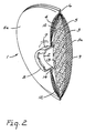
- the filter element 1 of this invention comprises a front wall 3, a rear wall 4, and layer of porous material 5 serving to space the front and rear walls and functioning as a baffle component to more evenly distribute air flow through the filter element, and a breather tube 8.
- the front wall 3, rear wall 4, and baffle component 5 are substantially coextensive with each other and said baffle component 5 is contained between the front and rear walls 3,4.
- the filter element 1 can have various shapes such as round, rectangular, or oval, but preferably, the filter element is round as depicted in Figs. 1 and 2.
- Filter element size can vary depending upon the materials of construction selected for the filter element 1 and upon various design and performance criteria known to those skilled in the art, e.g., the desired pressure drop across the filter, and the type and amount of dust, mist, or fumes to be removed from the wearer's inhaled air.
- shape and size of a filter element should not obstruct the wearer's eyesight when mounted on the respirator face piece 15.
- the front and rear walls 3,4 are joined along their peripheral edges by a number of bonding methods such as thermomechanical methods (e.g., ultrasonic welding), sewing, and adhesive such that a bond 6 is formed that prevents the leakage of air into or out of the filter element 1.
- the baffle component 5 is also joined to the front and rear wall 3,4 through the bond 6.
- the filter element 1 has a breather tube 8 which can have various shapes and can be formed from various materials such as synthetic resin or rubber.
- the breather tube is made of a synthetic resin which is heat sealable, e.g., polypropylene and is cylindrical in shape.
- the breather tube 8 can be mounted anywhere along the interior 10 or exterior 12 surface of the rear wall 4 but preferably the breather tube 8 is mounted centrally to the interior surface 10 of the rear wall 4.
- the breather tube 8 may be mounted to the chosen wall surface 10 or 12 using any suitable means, e.g., adhesive or ultrasonic welding.
- the rear wall 4 has an opening 7 adapted to fit the breather tube 8.
- the breather tube 8 is bonded to the rear wall 4 to prevent air leakage into or out of the filter element 1.
- the breather tube 8 has a flange 13 on the end of the breather tube 8 articulating with the interior surface 10 of the rear wall 4.
- This flange 13 provides a convenient surface 14 for bonding to the interior surface of the rear wall 10.
- the other end of the breather tube 8 can be adapted to either join directly with the respirator face piece 15, or as illustrated in Fig. 1, to join to an adapter 17 which is joined to the respirator face piece 15.
- One advantage of this invention is that the wearer can conveniently test the fit or airtightness of the seal between the wearer's face and the face piece 15 by pressing against the exterior surface 9 of the front wall 3 opposite the breather tube 8 to cause the front wall 3 and baffle component 5 to collapse against the breather tube opening 2 thereby blocking off air flow through the filter element 1.
- the wearer than inhales while the face piece 15 is held against his face thereby creating a negative pressure differential in the face piece. The wearer can then determine whether there are leaks between the face piece 15 and his face because these areas will fail to seal.
- the inner diameter (ID) of the breather tube is preferably 1.0 to 4.0 cm, and more preferably 1.5 to 3.5 cm.
- ID inner diameter
- OD breather tube outer diameter
- the breather tube 8 may include a valve, typically a diaphragm valve 18 as depicted in Fig. 1.
- the valve allows the wearer to draw filtered air out of the filter element 1 into the respirator face piece 15 but prevents the wearer's exhaled air from entering the filter element 1, thereby directing exhaled air out of the face piece 15 through an exhalation point such as an exhalation valve 19.
- the optional valve is part of the respirator face piece 15 or the adapter 17.
- the front and rear walls 3,4 are comprised of material which can function as filter material, with or without an outer cover or scrim.
- the selection of the materials of construction for the front and rear walls 3,4 will depend upon design factors well known to those skilled in the art, such as the type of environment in which a respirator equipped with the filter elements is to be used, and performance requirements such as the pressure drop across the respirator, the type and amount of dust, mist, or fume to be removed from the wearer's inhaled air, and design requirements set out in 30 C.F.R. 11, subpart K ⁇ 11.130-11.140-12 (1987), herein incorporated by reference.
- front and rear walls 3,4 of the filter element 1 can each be comprised of only a single layer of filter material, a plurality of layers is preferred for high performance filter elements.
- a plurality of layers of filter material By using a plurality of layers of filter material, web irregularities which could lead to premature penetration of particles though a single layer of filter material can be minimized.
- very thick walls should be avoided because they create problems in assembling the filter element 1 and could cause the filter element 1 to become so thick that it could obstruct the wearer's vision when in use.
- suitable filter material include nonwoven web, fibrillated film web, air-laid web, sorbent-particle-loaded fibrous web such as those described in U.S. Pat. No. 3,971,373 (Braun), glass filter paper, or combinations thereof.
- the filter material may comprise, for example, polyolefins, polycarbonates, polyesters, polyurethanes, glass, cellulose, carbon, alumina or combinations thereof.
- Electrically charged nonwoven microfiber webs See U.S. Pat. No. 4,215,682 (Kubik et al.) or U.S. Reissue Pat. No. 30,782 (Van Turnhout)) are especially preferred.
- a filter material comprising a plurality of layers of charged, blown polyolefin microfiber (BMF) web is preferred, with an electrically charged polypropylene web being more preferred.
- BMF charged, blown polyolefin microfiber
- Carbon-particle- or alumina-particle-loaded fibrous webs are also preferred filter media for this invention when protection from gaseous materials is desired.
- the front and rear walls 3, 4 preferably include outer cover layers 3a, 4a respectively which may be made from any woven or nonwoven material such as spun-bonded web, thermally bonded webs (e.g., air-laid or carded), or resin-bonded webs.
- the cover layers are made of spun-bonded or carded, thermally bonded webs with high hydrophobicity such as those made of polyolefins, e.g., polypropylene.
- the cover layers protect and contain the filter material, and may serve as an upstream prefilter layer.
- the baffle component 5 maintains the front and rear walls 3, 4 in a substantially spaced-apart relationship and also causes inhaled air to be drawn more evenly across the filter element 1. This results in more even loading of dust, mist, or fumes contained in inhaled air across the entire area of the filter element 1, in longer filter element service life, and for a given filter element construction, lower pressure drops across the filter element 1.
- the baffle component 5 can be made of woven or nonwoven webs, loose fibers, fiber batts, loose particulate material, e.g., carbon particles, particulate material bonded, e.g., with polyurethane together in a porous matrix, or combinations thereof.
- the baffle component material contained between the front and rear walls forms a porous layer that contributes no more than 50%, and preferably no more than 30%, of the pressure drop across the filter element.
- suitable baffle component materials are glass filter paper, air-laid webs, carded webs, fibrillated film webs, sorbent-particle-loaded fibrous webs, bonded sorbent particle matrices, or combinations thereof.
- the baffle component 5 comprises compressible, resilient, nonwoven web such as those formed by performing carding or air laying operations, (e.g., Rando Webbers) on blends of staple and binder fibers such that the fibers are bonded together at points of fiber intersection after the operation.
- the baffle component 5 can be made from natural materials such as glass, cellulose carbon, and alumina, synthetic materials such as polyester, polyamide, and polyolefin, polycarbonate, polyurethane, or combinations thereof.
- the baffle component 5 comprises polyester or polyolefin.
- sorbent-particle-loaded fibrous webs and particularly carbon- or alumina-particle-loaded webs, or sorbent-particles, e.g., carbon or alumina which may or may not be bonded together.
- the baffle component 5 should have sufficient void volume or porosity, and be thin enough to prevent the pressure drop across the filter element from becoming unacceptably high. It should also be thin enough to make assembly of the filter element 1 easy and to prevent the filter element 1 from becoming so thick that it obstructs the wearer's vision when the filter element 1 is mounted on a respirator face piece.
- the maximum acceptable pressure drop across the filter element 1 is determined by the comfort requirements of the wearer, and that as a practical matter, sometimes these pressure drops are determined by the standards, and measured according to the procedures set out in 30 C.F.R. 11, subpart K ⁇ 11.130-11.140-12 (1987).
- a thin baffle component also permits a thinner filter element which will be less obstructive to the wearer's vision.
- the baffle component 5 should be 0.2 cm to about 4.0 cm thick, and preferably 0.3 cm to 1.3 cm thick.
- a baffle component 5 comprising a nonwoven material should have at least a 10 micrometer average fiber diameter and a solidity of 11 percent or less.
- Filter elements of the present invention are further described by way of the non-limiting examples below.
- the silica dust loading test was performed in accordance with 30 C.F.R. 11 subpart K ⁇ 11.140-4.
- the lead fume test was performed in accordance with 30 C.F.R. 11 subpart K ⁇ 11.140-6.
- the DOP filter test was performed in accordance with 30 C.F.R. subpart K ⁇ 11.140-11.
- Filter elements were assembled by cutting the appropriate diameter circular front and rear walls, baffle component, and any cover layers from various materials which are specified below. A hole approximately 3.27 cm in diameter was cut through the rear wall of each filter element and the cover layer, if any, covering the rear wall.
- Each filter element had a cylindrical, 3.27 cm OD, 3.14 cm ID, 0.572 cm long, polypropylene breather tube with a 0.526 cm wide flange around the outer diameter of one end. The unflanged end of the breather tube was inserted through the hole in the rear wall and any cover layer and pulled through the hole until one surface of the flange contacted the interior surface of the rear wall. This flange surface was then bonded to the rear wall surface.
- the flange was ultrasonically welded using a Branson ultrasonic welder to the interior surface of the rear wall.
- the flange was bonded to the interior surface of the rear wall using a layer of 3M Jet-melt R adhesive 3764.
- the various layers were assembled in a sandwich-like structure where the baffle component was the innermost layer surrounded by the front and rear walls, and any cover layers formed the outermost layers of the sandwich.
- the peripheral edges of the polypropylene BMF, front and rear walls and baffle component were then ultrasonically welded together.
- the peripheral edges of the front and rear walls and baffle component of the filter element made with fiberglass paper were sealed using the hot melt adhesive described above.
- Circular filter elements 10.16 cm in diameter with front and rear walls made of six layers of electrically charged polypropylene BMF web similar to that described in US 4,215,682 (Kubik et al.), basis weight of approximately 55 g/m2 were constructed.
- the baffle components were 0.51 cm thick and were made of web which was prepared by carding blends of polyester (PET) staple fibers of the specified diameter, and binder fibers (i.e.
- a sheath/core fiber comprising a polyester terephthalate core having a melting temperature of approximately 245°C and a sheath comprising a copolymer of ethylene terephthalate and ethylene isophthalate, available as Melty Fiber Type 4080 from Unitika Ltd, Osaka Japan) of various diameters, in a 65:35 PET/binder fiber weight ratio and subsequently placing the carded web in a circulating air oven at 143°C for about 1 minute to activate the binder fibers and consolidate the web.
- the various solidities, of the baffle component, fiber diameters of the PET and binder fibers, and average fiber diameters of the fiber blends used in the baffle component web are summarized in Table 1.
- the filter elements were assembled according to the procedure described above. Pressure drops were measured for each filter element using the procedure referenced above. The pressure drops are summarized in Table 1. The data shows that both the average fiber diameter and solidity of the nonwoven material comprising the baffle component affects the pressure drop across the filter element and that fiber diameters as low as 13.8 micrometers produced acceptably low filter element pressure drops.
- Circular filter elements similar to those described in Examples 1-12 were assembled except that these filter elements had baffle components made of woven (scrim) and nonwoven materials of various thicknesses.
- the woven web used to made the baffle components was a polypropylene rectangular mesh scrim 0.05 cm thick commercially available from Conwed as ON 6200.
- the nonwoven web used for the baffle component was made according to a similar procedure used to made the nonwoven baffle web used in Examples 1-12 except that a 50:50 blend of a 51 micrometer diameter polyester staple fiber and 20.3 micrometer diameter, Eastman T-438, polyester binder fiber was used, and the web was calendered to a thickness of 0.07 cm after it came out of the oven. The pressure drops across the filter elements were measured according to the procedure referenced above.
- baffle component solidity and thickness affect the pressure drop across the filter, so both should be considered when selecting baffle component material.
- filter elements 7.6, 10.2 and 12.7 cm diameter filter elements were prepared in the manner described above except that one set of filter elements with these diameters had front and rear walls made of two single layers of fiberglass paper (available from Hollingsworth & Vose, # HE 1021 Fiberglass Paper) and another set of filter elements with the same diameters had walls made of a single layer of the same electrically charged polypropylene BMF web used in Examples 1-12.
- the nonwoven web used for the 0.64 cm thick baffle components used in each filter element was made according to a similar procedure used to make the nonwoven baffle web used in Examples 1-12 except that a 20.3 micrometer diameter, Melty Fiber binder fiber was used.
- the filter elements were subjected to the silica dust loading test referenced above.
- Three circular filter elements having diameters of 7.6, 10.2 and 12.7 cm were constructed according to the procedure described above, using front and rear walls made of two single layers of fiberglass paper (available from Hollingsworth & Vose, # HE 1021 Fiberglass Paper), and baffle components 0.64 cm thick, made of nonwoven baffle component web identical to that used in Examples 17-22. Additionally, three circular, 10.2 cm diameter filter elements were constructed using front and rear walls made of a single layer of the same electrically charged polypropylene BMF web used in Examples 1-12 and 0.64 cm thick baffle components made of the same nonwoven baffle component web used in Examples 17-22.
- the filter elements used in Example 26 also incorporated a cover layer over the front and rear walls made of material similar to the baffle component web used in Examples 17-22, except that the web was calendered to a thickness of 0.033 cm after it came out of the oven.
- the filters were assembled and subjected to the lead fume loading test referenced above. Initial and final pressure drops across the filter elements and the level of lead fume penetration through the filters were measured. After testing, the filter elements were visually inspected to determine if there had been even loading of the lead fume across the surface of the filter element. The inspected filters were evenly loaded across both the front and rear wall surfaces. Filter construction, diameter and lead fume penetration test data are reported in Table 4. Table 4 Example Filter media Filter dia. (cm) Pen.
- the data shows that the polypropylene, BMF filter media provides the wearer with protection against lead fumes with significantly lower pressure drops than filter elements made with fiberglass media.
- Circular filter elements ranging in diameter from 7.6 to 10.2 cm were constructed using a single layer of fiberglass paper (available from Hollingsworth & Vose, Hovoglas R #HB-5331 Fiberglass Paper) for front and rear walls and a 0.64 cm thick baffle component made of the same web as the baffle components used in Examples 23-26. Additionally, a set of circular filter elements ranging in size from 7.6 to 10.2 cm diameter with front and rear walls made of a plurality of layers of the same electrically charged polypropylene BMF used in Examples 1-12 and a 0.64 cm thick baffle component made of the same web as the baffle components used in Examples 23-26 were constructed. All filter elements were constructed in accordance with the procedure described above.
- Circular filter elements similar to those described in Examples 1-12 were assembled except that these filter elements had baffle components made of particles of various diameters and materials.
- the particulate material when held between the front and rear walls formed a porous layer.
- Several of the examples were carbon particles classified by sieving.
- One of the examples was polybutylene resin pellets of uniform size.
- the pressure drops across the filter elements were measured according to the procedure referenced above.
- the baffle component materials and pressure drops are reported in Table 6.
- Table 6 Example Baffle material Average particle diameter (mm) Thickness (cm) Pressure drop (mm H2O) 37 carbon .93 .99 47.0 38 carbon 1.09 .86 40.1 39 carbon 1.29 .89 33.9 40 carbon 1.7 .91 32.6 41 polybutylene 3.0 1.02 24.7
- Filter elements 10.2 cm in diameter were constructed using front and rear walls of a single layer of the polypropylene BMF web used in Examples 1-12 and 0.64 cm thick baffle components made of the same nonwoven baffle component web used in Examples 17-22.
- Each filter element had a cylindrical, polypropylene breather tube.
- the breather tubes had various inner diameters, but their outer diameter was 3.27 cm.
- the filter elements were assembled according to the procedure described above and the pressure drop across each filter element was measured according to the procedure referenced above.
- the breather tube inner diameters and pressure drops are summarized in Table 7.
- Table 7 Example Breather tube ID (cm) Pressure drop (mm H2O) DOP pen (%) 42 1.27 5.1 9.5 43 1.59 3.7 10.1 44 1.91 3.2 9.7
Landscapes
- Health & Medical Sciences (AREA)
- General Health & Medical Sciences (AREA)
- Business, Economics & Management (AREA)
- Emergency Management (AREA)
- Pulmonology (AREA)
- Respiratory Apparatuses And Protective Means (AREA)
- Filtering Materials (AREA)
Claims (9)
- Filterelement (1), umfassend:(A) im wesentlichen gleich verlaufende Vorder- und Rückwände (3, 4), die an ihren Umfangsrändern miteinander verbunden sind und zwischen sich einen Innenraum bilden; wobei die Vorder- und Rückwände (3, 4) jeweils mindestens eine Schicht Filtermaterial umfassen, und die Rückwand (4) mit der Schicht Filtermaterial eine Öffnung (2) besitzt, die den Zugang zu dem durch die Vorder- und Rückwände (3, 4) gebildeten Innenraum ermöglicht;(B) ein Entlüftungsrohr (8), dessen eines Ende über die Öffnung (2) mit dem Innenraum zwischen den Vorder- und Rückwänden (3, 4) in Verbindung steht, und dessen anderes Ende das Filterelement (1) an dem Gesichtsteil (15) einer Atemschutzmaske befestigt; und(C) eine poröse Schicht (5), die zwischen den Vorder- und Rückwänden (3, 4) angeordnet ist;dadurch gekennzeichnet, daß sich die poröse Schicht (5) im wesentlichen in gleicher Richtung wie die Wände (3, 4) erstreckt und die Wände (3, 4) im wesentlichen über die gesamte Fläche im Abstand voneinander hält, nicht mehr als 50% des gesamten Druckabfalls an dem Filterelement (1) bewirkt und aus einem Material besteht, das ausgewählt ist aus der Gruppe umfassend Faservliese, lose Fasern, Faserflore, loses disperses Material, in einer porösen Matrix verklebtes disperses Material oder Kombinationen daraus.
- Filterelement nach Anspruch 1, des weiteren dadurch gekennzeichnet, daß es Deckschichten (3a, 4a) umfaßt.
- Filterelement nach Anspruch 1 oder 2, bei dem die poröse Schicht (5) saugfähige Teilchen umfaßt, die in einer porösen Matrix miteinander verklebt sind.
- Filterelement nach Anspruch 1 oder 2, bei dem die poröse Schicht (5) ein Faservlies ist, das ausgewählt ist aus der Gruppe umfassend Glasfilterpapier, Blasvlies, Krempelvlies, Vlies aus fibrillierten Folien, saugfähige Teilchen enthaltendes Faservlies oder Kombinationen daraus.
- Filterelement nach einem der vorhergehenden Ansprüche, des weiteren dadurch gekennzeichnet, daß die poröse Schicht eine Dicke von 0,2 cm bis 4,0 cm besitzt.
- Filterelement nach einem der vorhergehenden Ansprüche, des weiteren dadurch gekennzeichnet, daß das Filterelement(i) nicht mehr als 1,5 mg Quarzstaub mit einem mittleren geometrischen Teilchendurchmesser von 0,4-0,6 »m über einen Zeitraum von 90 Minuten bei einer Luftströmungsgeschwindigkeit von 16 Litern pro Minute durch das Filterelement hindurchdringen läßt,(ii) vor Ablauf der 90 Minuten an dem Filterelement einen Druckabfall von nicht mehr als 30 mm H₂O und nach Ablauf der 90 Minuten an dem Filterelement einen Druckabfall von nicht mehr als 50 mm H₂O aufweist.
- Filterelement nach einem der vorhergehenden Ansprüche, des weiteren dadurch gekennzeichnet, daß das Filterelement nicht mehr als etwa 3,0 % der in dem Strom in einer Konzentration von 100 »g/l enthaltenen Dioctylphthalatteilchen mit einer Strömungsgeschwindigkeit von 42,5 Litern pro Minute hindurchdringen läßt.
- Filterelement nach einem der vorhergehenden Ansprüche, des weiteren dadurch gekennzeichnet, daß das Filterelement nicht mehr als 1,5 mg Bleidämpfe über einen Zeitraum von 312 Minuten bei einer Luftströmungsgeschwindigkeit von 16 Litern pro Minute durch das Filterelement hindurchdringen läßt, vor Ablauf der 312 Minuten an dem Filterelement einen Druckabfall von nicht mehr als 30 mm H₂O und nach Ablauf der 312 Minuten an dem Filterelement einen Druckabfall von nicht mehr als 50 mm H₂O aufweist.
- Atemschutzmaske umfassend ein Gesichtsteil (15) und ein oder mehrere Filterelemente (1) nach einem der vorhergehenden Ansprüche.
Applications Claiming Priority (2)
| Application Number | Priority Date | Filing Date | Title |
|---|---|---|---|
| US195029 | 1980-10-08 | ||
| US07/195,029 US4886058A (en) | 1988-05-17 | 1988-05-17 | Filter element |
Publications (3)
| Publication Number | Publication Date |
|---|---|
| EP0342807A2 EP0342807A2 (de) | 1989-11-23 |
| EP0342807A3 EP0342807A3 (de) | 1992-05-06 |
| EP0342807B1 true EP0342807B1 (de) | 1995-08-23 |
Family
ID=22719795
Family Applications (1)
| Application Number | Title | Priority Date | Filing Date |
|---|---|---|---|
| EP89304287A Expired - Lifetime EP0342807B1 (de) | 1988-05-17 | 1989-04-28 | Filterelement |
Country Status (13)
| Country | Link |
|---|---|
| US (2) | US4886058A (de) |
| EP (1) | EP0342807B1 (de) |
| JP (1) | JP2994402B2 (de) |
| KR (1) | KR960005210B1 (de) |
| AR (1) | AR244095A1 (de) |
| AU (1) | AU617454B2 (de) |
| BR (1) | BR8902282A (de) |
| CA (1) | CA1332716C (de) |
| DE (1) | DE68923906T2 (de) |
| DK (1) | DK175092B1 (de) |
| ES (1) | ES2076208T3 (de) |
| MX (1) | MX168560B (de) |
| ZA (1) | ZA893011B (de) |
Families Citing this family (145)
| Publication number | Priority date | Publication date | Assignee | Title |
|---|---|---|---|---|
| US4886058A (en) * | 1988-05-17 | 1989-12-12 | Minnesota Mining And Manufacturing Company | Filter element |
| US4981134A (en) * | 1990-01-16 | 1991-01-01 | Courtney Darryl W | Filtering face mask with inhalation/exhalation check valves |
| WO1991018647A1 (en) * | 1990-06-04 | 1991-12-12 | Air-Ace Oy | Respirator |
| US5140980A (en) * | 1990-06-13 | 1992-08-25 | Ilc Dover, Inc. | Hood mask and air filter system and method of manufacture thereof |
| USD339658S (en) | 1991-05-02 | 1993-09-21 | Air-Ace Oy | Respirator |
| US5240479A (en) * | 1991-05-17 | 1993-08-31 | Donaldson Company, Inc. | Pleated filter media having a continuous bead of adhesive between layers of filtering material |
| US5394867A (en) * | 1991-06-05 | 1995-03-07 | Brookdale International Systems Inc. | Personal disposable emergency breathing system with dual air supply |
| US5186165A (en) * | 1991-06-05 | 1993-02-16 | Brookdale International Systems Inc. | Filtering canister with deployable hood and mouthpiece |
| US5456248A (en) * | 1992-10-14 | 1995-10-10 | Stackhouse, Inc. | Surgical smoke evacuator |
| EP0669993B1 (de) * | 1992-11-18 | 1997-12-29 | Hoechst Celanese Corporation | Verfahren zur herstellung einer faserigen struktur mit immobilisiertem teilchenförmigem material |
| WO1995005501A2 (en) | 1993-08-17 | 1995-02-23 | Minnesota Mining And Manufacturing Company | Method of charging electret filter media |
| WO1995009676A1 (en) | 1993-10-01 | 1995-04-13 | Minnesota Mining And Manufacturing Company | Speech transmission adaptor for use with a respirator mask |
| US5720789A (en) * | 1994-09-06 | 1998-02-24 | Lockheed Idaho Technologies Company | Method for contamination control and barrier apparatus with filter for containing waste materials that include dangerous particulate matter |
| US5759394A (en) * | 1996-11-27 | 1998-06-02 | Alliedsignal Inc. | Elongate fiber filter mechanically securing solid adsorbent particles between adjacent multilobes |
| US6216693B1 (en) | 1995-01-20 | 2001-04-17 | 3M Innovative Properties Company | Respirator having a compressible press fir filter element |
| US5908598A (en) * | 1995-08-14 | 1999-06-01 | Minnesota Mining And Manufacturing Company | Fibrous webs having enhanced electret properties |
| USD382341S (en) * | 1996-03-27 | 1997-08-12 | Mine Safety Appliances Company | Respirator face mask |
| US5924420A (en) | 1996-09-24 | 1999-07-20 | Minnesota Mining And Manufacturing Company | Full face respirator mask having integral connectors disposed in lens area |
| US5732695A (en) * | 1997-03-11 | 1998-03-31 | Parmelee Industries | Respirator filtration device |
| US6044842A (en) * | 1997-05-19 | 2000-04-04 | Pereira; Michael | Gasketless connecting adapter |
| US6213122B1 (en) | 1997-10-01 | 2001-04-10 | 3M Innovative Properties Company | Electret fibers and filter webs having a low level of extractable hydrocarbons |
| US5895537A (en) * | 1997-10-09 | 1999-04-20 | Campbell; Richard G. | Sonic welded gas mask and process |
| US6161540A (en) | 1998-04-28 | 2000-12-19 | Cabot Safety Intermediate Corporation | Respirator filter having a pleated filter layer |
| US6345620B2 (en) | 1998-10-23 | 2002-02-12 | Mine Safety Appliances Company | Flexible respirator filter |
| DE19851322C1 (de) * | 1998-11-06 | 2000-03-02 | Draeger Sicherheitstech Gmbh | Atemschutzmaske |
| US6467481B1 (en) * | 1999-04-29 | 2002-10-22 | Vase Technology | Stackable filter device |
| US7311880B2 (en) * | 1999-12-23 | 2007-12-25 | 3M Innovative Properties Company | Well-less filtration device |
| US6627072B1 (en) * | 2000-03-04 | 2003-09-30 | Robert A. Ridge | Filter system for a paraffin spa |
| US6793702B2 (en) | 2000-06-28 | 2004-09-21 | Muniyapla Eswarappa | Filter cartridge platform and filter cartridge for use on the platform |
| USD477401S1 (en) | 2000-08-03 | 2003-07-15 | 3M Innovative Properties Company | Pair of filter cartridges for a powered air-purifying respirator |
| USD465568S1 (en) | 2000-08-03 | 2002-11-12 | 3M Innovative Properties Company | Cover for a filter cartridge |
| WO2002013946A2 (en) * | 2000-08-17 | 2002-02-21 | Vase Technology | Bi/multi-directional filter cartridge and filter platform for mounting the cartridge thereon |
| DE20017940U1 (de) | 2000-10-19 | 2000-12-28 | MAP Medizintechnik für Arzt und Patient GmbH & Co KG, 82152 Planegg | Atemmaske zur Zufuhr eines Atemgases zu einem Maskenanwender sowie Ableitungseinrichtung zur Ableitung von Atemgas |
| BR0209549B1 (pt) * | 2001-05-11 | 2012-01-24 | peça de face para respirador. | |
| DE10201682A1 (de) | 2002-01-17 | 2003-07-31 | Map Medizin Technologie Gmbh | Atemmaskenanordnung |
| ATE473774T1 (de) | 2001-10-22 | 2010-07-15 | Map Medizin Technologie Gmbh | Medizinische maske |
| DE10151984C5 (de) | 2001-10-22 | 2008-07-17 | Map Medizin-Technologie Gmbh | Applikationsvorrichtung für eine Atemmaskenanordnung |
| US20030089089A1 (en) | 2001-10-31 | 2003-05-15 | Fecteau Keith E. | Respirator filter element |
| US6736138B2 (en) * | 2001-11-10 | 2004-05-18 | Amad Tayebi | Seamless pad-type filter |
| US7334579B2 (en) * | 2001-11-10 | 2008-02-26 | Amad Tayebi | Low resistance to flow filter |
| US6701925B1 (en) | 2002-04-11 | 2004-03-09 | Todd A. Resnick | Protective hood respirator |
| NO316496B1 (no) * | 2002-06-10 | 2004-02-02 | Laerdal Medical As | Deksel for pasientmaske |
| US6659102B1 (en) | 2002-07-23 | 2003-12-09 | Anthony L. Sico | Oxygen mask filter system |
| DE202004021829U1 (de) | 2003-05-02 | 2011-05-26 | ResMed Ltd., New South Wales | Ein Maskensystem |
| RU2281798C2 (ru) * | 2004-10-26 | 2006-08-20 | ГУП "Казанский химический научно-исследовательский институт" | Фильтросорбирующий материал для средств индивидуальной защиты органов дыхания |
| US7320722B2 (en) * | 2004-10-29 | 2008-01-22 | 3M Innovative Properties Company | Respiratory protection device that has rapid threaded clean air source attachment |
| US8057567B2 (en) | 2004-11-05 | 2011-11-15 | Donaldson Company, Inc. | Filter medium and breather filter structure |
| US8021457B2 (en) | 2004-11-05 | 2011-09-20 | Donaldson Company, Inc. | Filter media and structure |
| EP1827649B1 (de) | 2004-11-05 | 2013-02-27 | Donaldson Company, Inc. | Filtermedium und -struktur |
| US12172111B2 (en) | 2004-11-05 | 2024-12-24 | Donaldson Company, Inc. | Filter medium and breather filter structure |
| US20060096911A1 (en) * | 2004-11-08 | 2006-05-11 | Brey Larry A | Particle-containing fibrous web |
| US8177875B2 (en) | 2005-02-04 | 2012-05-15 | Donaldson Company, Inc. | Aerosol separator; and method |
| WO2006091594A1 (en) | 2005-02-22 | 2006-08-31 | Donaldson Company, Inc. | Aerosol separator |
| NZ591992A (en) | 2005-10-14 | 2012-11-30 | Resmed Ltd | Breathing mask with cushion attached to frame via lip of cushion engaging within recess between frame outer and inner walls, and guided in via angled protrusion of frame inner wall |
| US9216306B2 (en) | 2005-12-22 | 2015-12-22 | 3M Innovative Properties Company | Filter element that has plenum containing bonded continuous filaments |
| US20090277451A1 (en) * | 2006-11-13 | 2009-11-12 | Stanley Weinberg | Strapless cantilevered respiratory mask sealable to a user's face and method |
| US20080110469A1 (en) * | 2006-11-13 | 2008-05-15 | Stanley Weinberg | Strapless flexible tribo-charged respiratory facial mask and method |
| US20080156329A1 (en) * | 2007-01-03 | 2008-07-03 | Gerson Ronald L | Cartridge Respirator with Integral Filter Adaptor |
| US8517023B2 (en) | 2007-01-30 | 2013-08-27 | Resmed Limited | Mask system with interchangeable headgear connectors |
| EP2117674A1 (de) | 2007-02-22 | 2009-11-18 | Donaldson Company, Inc. | Filterelement und verfahren |
| WO2008103821A2 (en) | 2007-02-23 | 2008-08-28 | Donaldson Company, Inc. | Formed filter element |
| US8820326B2 (en) * | 2007-08-31 | 2014-09-02 | 3M Innovative Properties Company | Respirator facepiece with thermoset elastomeric face seal |
| PL2183031T3 (pl) * | 2007-08-31 | 2018-10-31 | 3M Innovative Properties Company | Jednostkowa maska respiratora z formowanymi, termoutwardzalnymi elementami elastomerowymi |
| ES2639423T3 (es) * | 2007-08-31 | 2017-10-26 | 3M Innovative Properties Company | Componente de adhesión a un respirador con precinto elastomérico termoendurecido moldeado |
| CA2708117C (en) | 2007-12-06 | 2015-08-25 | John M. Sebastian | Electret webs with charge-enhancing additives |
| CN108114357B (zh) | 2008-03-04 | 2021-05-07 | 瑞思迈私人有限公司 | 面罩系统 |
| US11331447B2 (en) | 2008-03-04 | 2022-05-17 | ResMed Pty Ltd | Mask system with snap-fit shroud |
| US8613795B2 (en) | 2008-06-02 | 2013-12-24 | 3M Innovative Properties Company | Electret webs with charge-enhancing additives |
| US7765698B2 (en) | 2008-06-02 | 2010-08-03 | 3M Innovative Properties Company | Method of making electret articles based on zeta potential |
| US8267681B2 (en) | 2009-01-28 | 2012-09-18 | Donaldson Company, Inc. | Method and apparatus for forming a fibrous media |
| USD652506S1 (en) * | 2009-02-02 | 2012-01-17 | 3M Innovative Properties Company | Filter cartridge having a magenta netting |
| USD652910S1 (en) * | 2009-02-02 | 2012-01-24 | 3M Innovative Properties Company | Filter cartridge |
| KR100978602B1 (ko) * | 2009-03-13 | 2010-08-27 | 정정대 | 방진필터 제조방법 |
| EP2414576B1 (de) | 2009-04-03 | 2016-11-09 | 3M Innovative Properties Company | Verarbeitungshilfe für bahnmaterialien, einschliesslich elektret-bahnmaterial |
| JP5706875B2 (ja) | 2009-04-03 | 2015-04-22 | スリーエム イノベイティブ プロパティズ カンパニー | 帯電強化添加剤を含むエレクトレットウェブ |
| KR101013242B1 (ko) * | 2009-04-28 | 2011-02-09 | 우제정 | 마스크용 커버체 |
| KR100959146B1 (ko) * | 2009-08-03 | 2010-05-25 | (주)씨앤투스 | 호흡마스크용 필터 |
| KR100943196B1 (ko) * | 2009-08-03 | 2010-02-19 | (주)씨앤투스 | 호흡마스크용 필터 |
| US8460423B2 (en) * | 2010-05-20 | 2013-06-11 | 3M Innovative Properties Company | Filter cartridge having central plenum and housing sidewall |
| US8984753B2 (en) | 2010-05-20 | 2015-03-24 | 3M Innovative Properties Company | Method of making filter cartridge having roll-based housing sidewall |
| CA2806457A1 (en) | 2010-08-06 | 2012-02-09 | Scott Technologies, Inc. | Method and apparatus for integrating chemical and environmental sensors into an air purification filter through a reusable sensor post |
| KR101051109B1 (ko) * | 2010-12-09 | 2011-07-21 | 정정대 | 방진 마스크용 필터 |
| US9011584B2 (en) * | 2011-08-25 | 2015-04-21 | Honeywell International Inc. | End of service life indicator for respirator |
| US9393448B2 (en) | 2011-11-17 | 2016-07-19 | 3M Innovative Properties Company | Side plug-in filter cartridge |
| US8887719B2 (en) | 2011-12-15 | 2014-11-18 | 3M Innovative Properties Company | Air filtration device having tuned air distribution system |
| US8899227B2 (en) | 2011-12-15 | 2014-12-02 | 3M Innovative Properties Company | Air filtration device having subsections lacking fluid communication |
| WO2013165984A1 (en) * | 2012-04-30 | 2013-11-07 | Scott Technologies, Inc. | Half facepiece |
| US9192796B2 (en) * | 2012-10-25 | 2015-11-24 | Honeywell International Inc. | Method of donning and testing abrasive blast respirator |
| US9162088B2 (en) | 2012-10-25 | 2015-10-20 | Honeywell International Inc. | Method of assembly and disassembly of abrasive blast respirator |
| US9192794B2 (en) | 2012-10-25 | 2015-11-24 | Honeywell International Inc. | Noise reduction system for supplied air respirator |
| US9192793B2 (en) | 2012-10-25 | 2015-11-24 | Honeywell International Inc. | Abrasive blast respirator |
| US9510626B2 (en) | 2013-02-01 | 2016-12-06 | 3M Innovative Properties Company | Sleeve-fit respirator cartridge |
| AR095434A1 (es) * | 2013-03-15 | 2015-10-14 | Scott Tech Inc | Interfaz de filtro de respirador |
| US9814913B2 (en) | 2013-11-15 | 2017-11-14 | 3M Innovative Properties Company | Respirator with floating elastomeric sleeve |
| KR101530869B1 (ko) * | 2014-03-06 | 2015-06-23 | 팩컴코리아(주) | 일상 생활용 마스크 |
| USD746438S1 (en) | 2014-05-22 | 2015-12-29 | 3M Innovative Properties Company | Respirator filter cover |
| USD744088S1 (en) | 2014-05-22 | 2015-11-24 | 3M Innovative Properties Company | Respirator mask having a circular button |
| USD759807S1 (en) | 2014-05-22 | 2016-06-21 | 3M Innovative Properties Company | Respirator mask exhalation port |
| USD746437S1 (en) | 2014-05-22 | 2015-12-29 | 3M Innovative Properties Company | Respirator mask having a communication grille |
| USD757928S1 (en) | 2014-05-22 | 2016-05-31 | 3M Innovative Properties Company | Respirator cartridge body |
| USD754844S1 (en) | 2014-05-22 | 2016-04-26 | 3M Innovative Properties Company | Respirator mask |
| USD757247S1 (en) | 2014-05-22 | 2016-05-24 | 3M Innovative Properties Company | Respirator cartridge |
| USD745962S1 (en) | 2014-05-22 | 2015-12-22 | 3M Innovative Properties Company | Respirator filter retainer |
| USD787660S1 (en) | 2014-05-22 | 2017-05-23 | 3M Innovative Properties Company | Respirator mask having a face seal flexing region |
| US11235182B2 (en) | 2014-09-05 | 2022-02-01 | Honeywell International Inc. | End of service life indicator for disposal mask |
| DE102014017533A1 (de) * | 2014-11-21 | 2016-05-25 | Jrp Vision Ltd. | Luftzuführeinrichtung |
| KR101524219B1 (ko) * | 2014-12-16 | 2015-05-29 | 삼공물산 주식회사 | 정화통의 결합구조 및 이를 포함하는 방독면 |
| USD786443S1 (en) | 2015-02-27 | 2017-05-09 | 3M Innovative Properties Company | Filter element |
| USD767116S1 (en) | 2015-02-27 | 2016-09-20 | 3M Innovative Properties Company | Respirator mask having an exhalation port |
| USD741475S1 (en) | 2015-02-27 | 2015-10-20 | 3M Innovation Properties Company | Respirator mask having a communication grille |
| USD779674S1 (en) | 2015-02-27 | 2017-02-21 | 3M Innovative Properties Company | Filter element having a connector |
| USD743536S1 (en) | 2015-02-27 | 2015-11-17 | 3M Innovative Properties Company | Respirator mask having a circular button |
| USD742504S1 (en) | 2015-02-27 | 2015-11-03 | 3M Innovative Properties Company | Respirator mask |
| USD762845S1 (en) | 2015-02-27 | 2016-08-02 | 3M Innovative Properties Company | Respirator cartridge |
| USD795416S1 (en) | 2015-02-27 | 2017-08-22 | 3M Innovative Properties Company | Respirator mask |
| USD763437S1 (en) | 2015-02-27 | 2016-08-09 | 3M Innovative Properties Company | Respirator cartridge body |
| USD792959S1 (en) | 2015-02-27 | 2017-07-25 | 3M Innovative Properties Company | Filter element having a pattern |
| EP3261729B1 (de) | 2015-02-27 | 2019-08-28 | 3M Innovative Properties Company | Flexibles filterelement mit einem auslass |
| USD795415S1 (en) | 2015-02-27 | 2017-08-22 | 3M Innovative Properties Company | Respirator cartridge having an engagement latch |
| USD747795S1 (en) | 2015-02-27 | 2016-01-19 | 3M Innovative Properties Company | Respirator mask body |
| CN108883321A (zh) | 2016-03-28 | 2018-11-23 | 3M创新有限公司 | 头戴件悬架附接元件 |
| USD842982S1 (en) | 2016-03-28 | 2019-03-12 | 3M Innovative Properties Company | Hardhat suspension adapter for half facepiece respirators |
| KR102450400B1 (ko) | 2016-03-28 | 2022-10-04 | 쓰리엠 이노베이티브 프로퍼티즈 캄파니 | 호흡기 적합성 검사 밀봉 장치 및 방법 |
| USD816209S1 (en) | 2016-03-28 | 2018-04-24 | 3M Innovative Properties Company | Respirator inlet port connection seal |
| USD827810S1 (en) | 2016-03-28 | 2018-09-04 | 3M Innovative Properties Company | Hardhat suspension adapter for half facepiece respirators |
| KR102420496B1 (ko) | 2016-03-28 | 2022-07-13 | 쓰리엠 이노베이티브 프로퍼티즈 캄파니 | 다중 챔버 호흡기 밀봉 장치 및 방법 |
| WO2017196726A1 (en) * | 2016-05-11 | 2017-11-16 | 3M Innovative Properties Company | Adaptor for connecting a filter cartridge to a respirator mask |
| WO2018127939A1 (en) * | 2017-01-07 | 2018-07-12 | Mahesh Kudav | Twist and click locking mechanism of replaceable non symmetrical filter and inner yoke fitting part of half mask face piece |
| CN106853273A (zh) * | 2017-03-08 | 2017-06-16 | 成都凯力科技有限公司 | 一种过滤口罩 |
| IT201800001827A1 (it) * | 2018-01-25 | 2019-07-25 | Mares Spa | Valvola a membrana ed un metodo per la sua realizzazione |
| US11123583B2 (en) * | 2018-04-19 | 2021-09-21 | Jackson Nestelroad | Emergency aircraft passenger oxygen respirator |
| KR20220024679A (ko) | 2019-06-28 | 2022-03-03 | 쓰리엠 이노베이티브 프로퍼티즈 캄파니 | 코어-시스 섬유, 부직 섬유질 웨브, 및 이를 포함하는 호흡기 |
| US20220323890A1 (en) | 2019-06-28 | 2022-10-13 | 3M Innovative Properties Company | Filter assembly, prefilter assembly, and respirator including the same |
| EP4093516A4 (de) * | 2020-01-20 | 2024-06-05 | O2 Industries Inc. | Taktische atemschutzmaske |
| WO2021202306A1 (en) * | 2020-03-28 | 2021-10-07 | Proveris Scientific Corporation | Respiration apparatus and methods of use thereof |
| KR20210130881A (ko) * | 2020-04-22 | 2021-11-02 | 쓰리엠 이노베이티브 프로퍼티즈 캄파니 | 스페이서, 호흡 보조 장치 및 이를 포함하는 마스크 |
| US20210372637A1 (en) * | 2020-06-02 | 2021-12-02 | Virender K. Sharma | Methods and Systems for Air Management to Reduce or Block Exposure to Airborne Pathogens |
| USD946746S1 (en) * | 2020-08-07 | 2022-03-22 | The United States Of America As Represented By The Secretary Of The Navy | Filtered face mask respirator |
| USD946744S1 (en) * | 2020-08-07 | 2022-03-22 | The United States Of America As Represented By The Secretary Of The Navy | Filtered face mask with cap |
| USD946745S1 (en) * | 2020-08-07 | 2022-03-22 | The United States Of America As Represented By The Secretary Of The Navy | Filtered face mask |
| JP7805360B2 (ja) | 2020-11-02 | 2026-01-23 | スリーエム イノベイティブ プロパティズ カンパニー | コア-シース繊維、不織繊維ウェブ、及びそれを含む濾過物品 |
| WO2022104207A1 (en) | 2020-11-16 | 2022-05-19 | National Technology & Engineering Solutions Of Sandia, Llc | Reusable filtering face mask |
| CN116744880A (zh) | 2020-12-18 | 2023-09-12 | 3M创新有限公司 | 包含取代的环状三磷腈化合物的驻极体以及由其制得的制品 |
| WO2022192389A1 (en) * | 2021-03-10 | 2022-09-15 | Milwaukee Electric Tool Corporation | Reusable respirator |
| EP4304740A4 (de) | 2021-03-10 | 2025-04-02 | Milwaukee Electric Tool Corporation | Wiederverwendbares atemschutzgerät |
Family Cites Families (35)
| Publication number | Priority date | Publication date | Assignee | Title |
|---|---|---|---|---|
| US32171A (en) * | 1861-04-30 | Coiffibinatioit-lbck | ||
| US30782A (en) * | 1860-11-27 | John wright | ||
| GB470850A (en) * | 1936-01-17 | 1937-08-17 | John Ambrose Sadd | Improvements in respirators and the like |
| US2206061A (en) * | 1936-11-06 | 1940-07-02 | American Optical Corp | Respirator |
| US2220374A (en) * | 1936-11-23 | 1940-11-05 | Howard B Lewis | Respirator |
| US2227959A (en) * | 1937-10-11 | 1941-01-07 | Harvey S Cover | Respirator filter |
| GB573951A (en) * | 1939-11-15 | 1945-12-14 | Henry Lionel Green | Improvements in filters |
| US2320770A (en) * | 1940-12-20 | 1943-06-01 | Harvey S Cover | Respirator |
| US2295119A (en) * | 1941-01-02 | 1942-09-08 | Malcom | Respirator |
| US3316904A (en) * | 1961-07-31 | 1967-05-02 | Minnesota Mining & Mfg | Filtering web for face masks and face masks made therefrom |
| GB1041394A (en) * | 1963-09-05 | 1966-09-07 | Martindale Electric Company Lt | Filter pads for sanitary masks and sanitary masks incorporating such pads |
| BE788211A (fr) * | 1971-09-16 | 1973-02-28 | Pall Corp | Appareil disposable pour filtrer les gaz |
| US3803817A (en) * | 1971-11-02 | 1974-04-16 | Ato Inc | Filter assembly |
| US3971373A (en) * | 1974-01-21 | 1976-07-27 | Minnesota Mining And Manufacturing Company | Particle-loaded microfiber sheet product and respirators made therefrom |
| US4011067A (en) * | 1974-01-30 | 1977-03-08 | Minnesota Mining And Manufacturing Company | Filter medium layered between supporting layers |
| NL160303C (nl) | 1974-03-25 | 1979-10-15 | Verto Nv | Werkwijze voor het vervaardigen van een vezelfilter. |
| US4064876A (en) * | 1976-01-30 | 1977-12-27 | Stanley I. Wolf | Air-pollution filter and face mask |
| US4133656A (en) * | 1976-03-23 | 1979-01-09 | Becton, Dickinson And Company | Bacteria filters with transparent housings |
| CA1100419A (en) * | 1977-01-05 | 1981-05-05 | John A. Jones | Organic vapor respirator cartridge end-of-service indicator system and method |
| US4133309A (en) * | 1977-05-13 | 1979-01-09 | Minnesota Mining And Manufacturing Company | Sorbent material and a respirator containing the sorbent material |
| US4215682A (en) * | 1978-02-06 | 1980-08-05 | Minnesota Mining And Manufacturing Company | Melt-blown fibrous electrets |
| US4386948A (en) * | 1979-12-20 | 1983-06-07 | American Hospital Supply Corporation | Filter drive |
| US4583535A (en) * | 1980-08-07 | 1986-04-22 | Saffo John J | Protection mask |
| US4414973A (en) * | 1981-03-10 | 1983-11-15 | U.S.D. Corp. | Respirator face mask |
| US4382440A (en) * | 1981-03-18 | 1983-05-10 | Kapp Nancy J | Smoke and pollutant filtering device |
| US4501272A (en) * | 1981-10-30 | 1985-02-26 | Shigematsu Works Co., Ltd. | Mask |
| US4572178A (en) * | 1983-04-01 | 1986-02-25 | Toyo Cci Kabushiki Kaisha | Emergency mask |
| US4543112A (en) * | 1984-04-30 | 1985-09-24 | Figgie International Inc. | Sorbent type filter assembly for a respirator and method of making same |
| US4556326A (en) * | 1984-10-09 | 1985-12-03 | Kitchen Iii George H | Method for testing and treating stored fuel |
| CA1264681A (en) * | 1985-07-03 | 1990-01-23 | Minister Of National Defence | Automated production of canisters |
| JPS62106778A (ja) * | 1985-11-05 | 1987-05-18 | 天昇電気工業株式会社 | 防煙マスク |
| US4807619A (en) * | 1986-04-07 | 1989-02-28 | Minnesota Mining And Manufacturing Company | Resilient shape-retaining fibrous filtration face mask |
| DE3719420A1 (de) * | 1987-06-11 | 1988-12-29 | Sandler Helmut Helsa Werke | Atemschutzmaske |
| US4754751A (en) * | 1987-06-11 | 1988-07-05 | Mine Safety Appliances Company | Escape respirator |
| US4886058A (en) * | 1988-05-17 | 1989-12-12 | Minnesota Mining And Manufacturing Company | Filter element |
-
1988
- 1988-05-17 US US07/195,029 patent/US4886058A/en not_active Ceased
-
1989
- 1989-04-18 AU AU33139/89A patent/AU617454B2/en not_active Ceased
- 1989-04-20 CA CA000597257A patent/CA1332716C/en not_active Expired - Fee Related
- 1989-04-24 ZA ZA893011A patent/ZA893011B/xx unknown
- 1989-04-28 EP EP89304287A patent/EP0342807B1/de not_active Expired - Lifetime
- 1989-04-28 DE DE68923906T patent/DE68923906T2/de not_active Expired - Fee Related
- 1989-04-28 ES ES89304287T patent/ES2076208T3/es not_active Expired - Lifetime
- 1989-05-03 MX MX015903A patent/MX168560B/es unknown
- 1989-05-15 JP JP1118861A patent/JP2994402B2/ja not_active Expired - Fee Related
- 1989-05-16 DK DK198902383A patent/DK175092B1/da not_active IP Right Cessation
- 1989-05-16 BR BR898902282A patent/BR8902282A/pt not_active IP Right Cessation
- 1989-05-16 KR KR1019890006536A patent/KR960005210B1/ko not_active Expired - Lifetime
- 1989-05-17 AR AR89313958A patent/AR244095A1/es active
-
1993
- 1993-06-17 US US08/079,234 patent/USRE35062E/en not_active Expired - Lifetime
Also Published As
| Publication number | Publication date |
|---|---|
| KR890016983A (ko) | 1989-12-14 |
| MX168560B (es) | 1993-05-31 |
| EP0342807A3 (de) | 1992-05-06 |
| AU3313989A (en) | 1989-11-23 |
| CA1332716C (en) | 1994-10-25 |
| ZA893011B (en) | 1990-12-28 |
| AR244095A1 (es) | 1993-10-29 |
| DK238389A (da) | 1989-11-18 |
| DE68923906D1 (de) | 1995-09-28 |
| KR960005210B1 (ko) | 1996-04-23 |
| EP0342807A2 (de) | 1989-11-23 |
| DK238389D0 (da) | 1989-05-16 |
| DE68923906T2 (de) | 1996-04-18 |
| AU617454B2 (en) | 1991-11-28 |
| JP2994402B2 (ja) | 1999-12-27 |
| USRE35062E (en) | 1995-10-17 |
| ES2076208T3 (es) | 1995-11-01 |
| US4886058A (en) | 1989-12-12 |
| JPH0219175A (ja) | 1990-01-23 |
| DK175092B1 (da) | 2004-05-24 |
| BR8902282A (pt) | 1990-01-09 |
Similar Documents
| Publication | Publication Date | Title |
|---|---|---|
| EP0342807B1 (de) | Filterelement | |
| CA1280851C (en) | High efficiency respirator | |
| JP5124080B2 (ja) | フィルター材料の周りに熱成形ハウジングを有するフィルター要素 | |
| US10136687B2 (en) | Filtering face-piece respirator having nose notch | |
| US6161540A (en) | Respirator filter having a pleated filter layer | |
| CA1140702A (en) | Operating room face mask | |
| US10602785B2 (en) | Filtering face-piece respirator having nose cushioning member | |
| US4883547A (en) | Method of forming a high efficiency respirator | |
| US4600002A (en) | Disposable respirator | |
| US20060201513A1 (en) | Flat-foldable face-mask and process of making same | |
| EP3038717A2 (de) | Atemmaske mit einem gesichtsfilterungsteil und einem maskenkörper mit klammern | |
| WO2003037440A1 (en) | Respirator filter element | |
| JPH07213635A (ja) | マスク用耐熱カバー、耐熱性防塵マスク及び耐熱性防塵マスク用の耐熱性フィルター要素 |
Legal Events
| Date | Code | Title | Description |
|---|---|---|---|
| PUAI | Public reference made under article 153(3) epc to a published international application that has entered the european phase |
Free format text: ORIGINAL CODE: 0009012 |
|
| AK | Designated contracting states |
Kind code of ref document: A2 Designated state(s): BE CH DE ES FR GB IT LI NL SE |
|
| 17P | Request for examination filed |
Effective date: 19910102 |
|
| PUAL | Search report despatched |
Free format text: ORIGINAL CODE: 0009013 |
|
| AK | Designated contracting states |
Kind code of ref document: A3 Designated state(s): BE CH DE ES FR GB IT LI NL SE |
|
| 17Q | First examination report despatched |
Effective date: 19931103 |
|
| GRAA | (expected) grant |
Free format text: ORIGINAL CODE: 0009210 |
|
| AK | Designated contracting states |
Kind code of ref document: B1 Designated state(s): BE CH DE ES FR GB IT LI NL SE |
|
| ITF | It: translation for a ep patent filed | ||
| REF | Corresponds to: |
Ref document number: 68923906 Country of ref document: DE Date of ref document: 19950928 |
|
| ET | Fr: translation filed | ||
| REG | Reference to a national code |
Ref country code: ES Ref legal event code: FG2A Ref document number: 2076208 Country of ref document: ES Kind code of ref document: T3 |
|
| PLBE | No opposition filed within time limit |
Free format text: ORIGINAL CODE: 0009261 |
|
| 26N | No opposition filed | ||
| REG | Reference to a national code |
Ref country code: GB Ref legal event code: IF02 |
|
| PGFP | Annual fee paid to national office [announced via postgrant information from national office to epo] |
Ref country code: NL Payment date: 20050329 Year of fee payment: 17 |
|
| PGFP | Annual fee paid to national office [announced via postgrant information from national office to epo] |
Ref country code: SE Payment date: 20050420 Year of fee payment: 17 |
|
| PGFP | Annual fee paid to national office [announced via postgrant information from national office to epo] |
Ref country code: CH Payment date: 20050421 Year of fee payment: 17 |
|
| PGFP | Annual fee paid to national office [announced via postgrant information from national office to epo] |
Ref country code: ES Payment date: 20050512 Year of fee payment: 17 |
|
| PGFP | Annual fee paid to national office [announced via postgrant information from national office to epo] |
Ref country code: BE Payment date: 20050520 Year of fee payment: 17 |
|
| PGFP | Annual fee paid to national office [announced via postgrant information from national office to epo] |
Ref country code: FR Payment date: 20060417 Year of fee payment: 18 |
|
| PGFP | Annual fee paid to national office [announced via postgrant information from national office to epo] |
Ref country code: GB Payment date: 20060424 Year of fee payment: 18 |
|
| PG25 | Lapsed in a contracting state [announced via postgrant information from national office to epo] |
Ref country code: SE Free format text: LAPSE BECAUSE OF NON-PAYMENT OF DUE FEES Effective date: 20060429 Ref country code: ES Free format text: LAPSE BECAUSE OF NON-PAYMENT OF DUE FEES Effective date: 20060429 |
|
| PG25 | Lapsed in a contracting state [announced via postgrant information from national office to epo] |
Ref country code: LI Free format text: LAPSE BECAUSE OF NON-PAYMENT OF DUE FEES Effective date: 20060430 Ref country code: CH Free format text: LAPSE BECAUSE OF NON-PAYMENT OF DUE FEES Effective date: 20060430 Ref country code: BE Free format text: LAPSE BECAUSE OF NON-PAYMENT OF DUE FEES Effective date: 20060430 |
|
| PGFP | Annual fee paid to national office [announced via postgrant information from national office to epo] |
Ref country code: IT Payment date: 20060430 Year of fee payment: 18 |
|
| PGFP | Annual fee paid to national office [announced via postgrant information from national office to epo] |
Ref country code: DE Payment date: 20060531 Year of fee payment: 18 |
|
| PG25 | Lapsed in a contracting state [announced via postgrant information from national office to epo] |
Ref country code: NL Free format text: LAPSE BECAUSE OF NON-PAYMENT OF DUE FEES Effective date: 20061101 |
|
| REG | Reference to a national code |
Ref country code: CH Ref legal event code: PL |
|
| EUG | Se: european patent has lapsed | ||
| NLV4 | Nl: lapsed or anulled due to non-payment of the annual fee |
Effective date: 20061101 |
|
| REG | Reference to a national code |
Ref country code: ES Ref legal event code: FD2A Effective date: 20060429 |
|
| GBPC | Gb: european patent ceased through non-payment of renewal fee |
Effective date: 20070428 |
|
| BERE | Be: lapsed |
Owner name: *MINNESOTA MINING AND MFG CY Effective date: 20060430 |
|
| PG25 | Lapsed in a contracting state [announced via postgrant information from national office to epo] |
Ref country code: DE Free format text: LAPSE BECAUSE OF NON-PAYMENT OF DUE FEES Effective date: 20071101 |
|
| PG25 | Lapsed in a contracting state [announced via postgrant information from national office to epo] |
Ref country code: GB Free format text: LAPSE BECAUSE OF NON-PAYMENT OF DUE FEES Effective date: 20070428 |
|
| PG25 | Lapsed in a contracting state [announced via postgrant information from national office to epo] |
Ref country code: FR Free format text: LAPSE BECAUSE OF NON-PAYMENT OF DUE FEES Effective date: 20070430 |
|
| PG25 | Lapsed in a contracting state [announced via postgrant information from national office to epo] |
Ref country code: IT Free format text: LAPSE BECAUSE OF NON-PAYMENT OF DUE FEES Effective date: 20070428 |