EP0342745A2 - Appareil d'examen à spin nucléaire comportant un agencement de bobines à haute fréquence - Google Patents
Appareil d'examen à spin nucléaire comportant un agencement de bobines à haute fréquence Download PDFInfo
- Publication number
- EP0342745A2 EP0342745A2 EP89201194A EP89201194A EP0342745A2 EP 0342745 A2 EP0342745 A2 EP 0342745A2 EP 89201194 A EP89201194 A EP 89201194A EP 89201194 A EP89201194 A EP 89201194A EP 0342745 A2 EP0342745 A2 EP 0342745A2
- Authority
- EP
- European Patent Office
- Prior art keywords
- frequency
- resonators
- coil arrangement
- coil
- frequency coil
- Prior art date
- Legal status (The legal status is an assumption and is not a legal conclusion. Google has not performed a legal analysis and makes no representation as to the accuracy of the status listed.)
- Granted
Links
Images
Classifications
-
- G—PHYSICS
- G01—MEASURING; TESTING
- G01R—MEASURING ELECTRIC VARIABLES; MEASURING MAGNETIC VARIABLES
- G01R33/00—Arrangements or instruments for measuring magnetic variables
- G01R33/20—Arrangements or instruments for measuring magnetic variables involving magnetic resonance
- G01R33/28—Details of apparatus provided for in groups G01R33/44 - G01R33/64
- G01R33/32—Excitation or detection systems, e.g. using radio frequency signals
- G01R33/34—Constructional details, e.g. resonators, specially adapted to MR
- G01R33/34046—Volume type coils, e.g. bird-cage coils; Quadrature bird-cage coils; Circularly polarised coils
- G01R33/34053—Solenoid coils; Toroidal coils
-
- G—PHYSICS
- G01—MEASURING; TESTING
- G01R—MEASURING ELECTRIC VARIABLES; MEASURING MAGNETIC VARIABLES
- G01R33/00—Arrangements or instruments for measuring magnetic variables
- G01R33/20—Arrangements or instruments for measuring magnetic variables involving magnetic resonance
- G01R33/28—Details of apparatus provided for in groups G01R33/44 - G01R33/64
- G01R33/32—Excitation or detection systems, e.g. using radio frequency signals
- G01R33/36—Electrical details, e.g. matching or coupling of the coil to the receiver
- G01R33/3628—Tuning/matching of the transmit/receive coil
-
- G—PHYSICS
- G01—MEASURING; TESTING
- G01R—MEASURING ELECTRIC VARIABLES; MEASURING MAGNETIC VARIABLES
- G01R33/00—Arrangements or instruments for measuring magnetic variables
- G01R33/20—Arrangements or instruments for measuring magnetic variables involving magnetic resonance
- G01R33/28—Details of apparatus provided for in groups G01R33/44 - G01R33/64
- G01R33/32—Excitation or detection systems, e.g. using radio frequency signals
- G01R33/36—Electrical details, e.g. matching or coupling of the coil to the receiver
- G01R33/3642—Mutual coupling or decoupling of multiple coils, e.g. decoupling of a receive coil from a transmission coil, or intentional coupling of RF coils, e.g. for RF magnetic field amplification
Definitions
- the invention relates to an MRI device with a high-frequency coil arrangement that can be connected to a high-frequency transmitter and / or to a high-frequency receiver.
- the signal-to-noise ratio when receiving nuclear magnetic resonance signals becomes less favorable the lower the magnetic flux density of the stationary homogeneous magnetic field to which the examination area is exposed during an MRI examination.
- the high-frequency coil arrangement which receives the magnetic resonance signals has a high quality and a high sensitivity.
- a so-called solenoid coil with a sufficient number of turns has these properties. However, the number of turns can only be chosen so large that the length of the conductor from which this coil is wound is less than a quarter wavelength of the operating frequency, preferably small in comparison.
- Murton and Neale have therefore described a coil arrangement in which two coils, each with three turns, are connected in parallel.
- the natural resonance frequency is still relatively low due to unavoidable coil capacitances, so that wave propagation effects can be noticed, which lead to an increase in the dielectric losses and thus to a decrease in the quality.
- the object of the present invention is to provide a high-frequency coil arrangement for a nuclear magnetic resonance device, which has a favorable signal-to-noise ratio and a high quality even at a comparatively low nuclear magnetic resonance frequency.
- the high-frequency coil arrangement comprises a plurality of resonators tuned to the same frequency, that each resonator comprises a one-part or multi-part conductor loop, the ends of which are capacitively coupled to one another, that the resonators which are not electrically connected are inductively coupled to one another and that in the operating state, one of the resonators is connected to the high-frequency transmitter or to the high-frequency receiver.
- the invention thus uses a number of resonators, each of which is formed by a conductor loop, which are generally tuned to the same frequency by means of an additional capacitor.
- the individual resonators are not galvanically connected to one another, but rather inductively coupled to one another. Only one of the resonators is connected to the high-frequency transmitter or to the high-frequency receiver during operation.
- Such a high-frequency coil arrangement therefore behaves like a high-frequency coil with only one turn with regard to the wave propagation effects and the associated dielectric losses, but with regard to sensitivity like a solenoid coil whose number of turns corresponds to the number of resonators.
- a high-frequency coil arrangement there are as many vibration modes as there are resonators.
- an oscillation mode the currents flow in the same direction in all resonators. This mode of shrinkage has the lowest resonance frequency linked, which is below the frequency to which the individual resonators are tuned.
- the currents in spatially adjacent resonators always have the opposite sense of rotation. This oscillation mode results in the highest resonance frequency, which is above the frequency to which the resonators are tuned.
- This mode of oscillation can only be excited by supplying a current with the relevant frequency to one of the resonators; however, it cannot be caused by an external homogeneous high-frequency field.
- a vertically running, homogeneous, stationary magnetic field acts on the examination area enclosed by the high-frequency coil arrangement.
- a patient is usually examined lying down in an MRI scanner.
- the high-frequency coil arrangement then has a horizontally running longitudinal axis and generates a high-frequency magnetic field running in this direction, to which the vertical, homogeneous and stationary magnetic field is perpendicular - as is necessary.
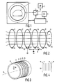
- the magnetic resonance tomograph shown in FIG. 1 contains a high-frequency coil arrangement 1 with a hollow cylindrical cross-section, which inside generates a high-frequency magnetic field that is perpendicular to the plane of the drawing and penetrates the examination area in which the examination object 2 is located, for example a patient whose longitudinal axis is perpendicular to the plane of the drawing runs.
- the magnetic resonance tomograph has a main field magnet, not shown, which generates a stationary, homogeneous magnetic field running in the vertical direction with a magnetic flux density of a few tenths of a T or less.
- the stationary magnetic field and the high-frequency field are therefore perpendicular to each other.
- there are also gradient coils - likewise not shown in detail - which also produce magnetic fields that run in the vertical direction, but with a gradient in one of three directions perpendicular to each other.
- a control unit 3 controls the generation of the fields described above and processes the nuclear magnetic resonance signals received from the examination area.
- it acts on an electronic switch 4, by means of which the radio-frequency coil arrangement 1 is switched from transmission mode - in which it is connected to an oscillator 5 - to reception mode, in which it is connected to a radio-frequency receiver 6, which amplifies, demodulates and demodulates the nuclear magnetic resonance signals converted into a sequence of digital data words that are processed in unit 3.
- the high-frequency coil arrangement 1 consists of a number of resonators 11 ... 15.
- the resonators are arranged on a cylindrical carrier body 10, the central axis 16 of which runs perpendicular to the homogeneous stationary magnetic field B0.
- Each resonator comprises a conductor loop which surrounds the carrier body in a ring and is only interrupted at a point which is capacitively bridged.
- the conductor loops are located in parallel planes which are preferably perpendicular to the longitudinal axis 16 of the carrier body 10.
- the capacitance of the open ends of the conductor loops 11 .. 15 bridging capacitors 110 ... 150 is chosen so that all resonators (by themselves) are tuned to the same resonance frequency.
- this tuning takes place by means of two capacitors 131 and 132 of equal size, connected in series, the connection point of which is grounded.
- the connection of one of the two capacitors (132) facing away from this connection point is connected to the changeover switch 4 (FIG. 1) via a matching and tuning network 8.
- the conductor loops can also be interrupted at a plurality of points which are evenly offset relative to one another on the circumference and can be bridged by a capacitor with a suitable capacitance. Although this increases the outlay, the dielectric losses occurring during operation are further reduced or the quality is further increased.
- the resonators formed by a conductor loop and one or two capacitors are not galvanically connected to one another. However, they are inductively coupled to one another because the conductor loops are located in parallel planes. Because of the missing Galvanic connection between the individual conductor loops, the propagation effects are determined only by the dimensions of the conductor loop 13 that can be coupled to the high-frequency transmitter 5 or the high-frequency receiver 6. With a diameter of the tube 10 of 600 mm, the length of such a conductor loop (almost 2 m) is still small compared to a quarter of the wavelength (35 m), which is at a magnetic flux density of the stationary homogeneous magnetic field B0 of 0.2 T and the associated magnetic resonance frequency of around 8.5 MHz.
- the inductive coupling between the different resonators results in a concentration of the generated magnetic field, which runs in the direction of the central axis 16 or perpendicular to the plane of the resonators, as indicated in FIG. 2, essentially in the space enclosed by the resonators - Similar to a solenoid coil with a corresponding number of turns.
- the quality and in particular the coil sensitivity are therefore the better the more resonators are present. In practice, therefore, more than just the five resonators shown in the figures will be used.
- the number of resonance frequencies corresponds to the number of resonators; the resonance frequency is the frequency at which the ratio of the energy in the resonator to the energy supplied to the resonator has a maximum.
- Each resonance frequency is linked to a different vibration mode. The lowest resonance frequency results when a current flows in the same direction in all resonators. This resonance frequency is lower than the frequency to which the individual resonators are tuned.
- the highest resonance frequency is obtained when the direction of current flow is reversed from resonator to resonator; this frequency is much higher than the frequency to which the resonators are tuned.
- the advantage of this mode of vibration is that it cannot be excited by a homogeneous external magnetic field. If one operates such a coil arrangement as a receiving coil in the field of an (additional) transmitting coil, there is a large decoupling between the coils, especially if the receiving coil consists of an even number of resonators.
- the advantage here is that conventional transmitter coils mostly also lie on a cylinder jacket, but generate a field perpendicular to the cylinder axis. The receiving coil can therefore be arranged concentrically to the transmitting coil in its interior.
- a high-frequency coil for nuclear spin examinations in the head area seven resonators were applied to a carrier body with a diameter of 320 mm. Each resonator consisted of 12 mm thick copper tube, which was tuned to a frequency of approximately 11 MHz using a 320 pF capacitor. The distance between the conductor loops was 20 mm. This arrangement was operated at the lowest resonance frequency, which was 6.8 MHz. This resulted in an idling quality of 120 and a loaded quality of about 280. Saddle coils have similarly high idling and operating speeds at such resonator frequencies quality so that they are not inferior in broadcast mode.
- the sensitivity of a saddle coil is around 40% lower, so that the high-frequency coil arrangement according to the invention has significant advantages in reception mode.
- the quality of a high-frequency coil arrangement according to the invention decreases far less than that of a saddle coil, so that there are advantages with regard to the transmission mode even at lower frequencies.
- a high frequency coil with a circular cross section has been described above.
- the high-frequency coil can also have a different cross section, for example an elliptical or a square one.
- the center points or the centroids of the surfaces enclosed by the individual conductor loops should lie on a common straight line, and the mutually parallel planes in which the conductor loops are located should intersect this straight line as perpendicularly as possible.
- a further conductor loop 17 can be provided, which is arranged concentrically to the central axis 16 and which has a smaller diameter than this.
- This conductor loop must be tuned to the same frequency as the other resonators, but this requires a capacitor 170 with a larger capacitance because of the reduced inductance of this loop.
- the effect of this smaller resonator 17, which is located at one end of the high-frequency coil arrangement, is expressed in that the magnetic flux density drops even more in the axial direction towards the outside, so that the magnetic field is concentrated even more in the space enclosed by the coils .
- a conductive screen 18 made of a 30 ⁇ m thick copper foil is arranged on the side of the coil facing away from the patient entry side. This increases the field in the center of the coil, thus additionally causing a field concentration and thus a better signal-to-noise ratio.
- a further screen 19 can be arranged, which is provided with an opening - indicated by dashed lines in FIG. 4 with 20 - for the patient's head . This shields the shoulder area of the patient and stray fields, which create an additional patient burden.
Landscapes
- Physics & Mathematics (AREA)
- Condensed Matter Physics & Semiconductors (AREA)
- General Physics & Mathematics (AREA)
- Magnetic Resonance Imaging Apparatus (AREA)
Applications Claiming Priority (2)
| Application Number | Priority Date | Filing Date | Title |
|---|---|---|---|
| DE3816831A DE3816831A1 (de) | 1988-05-18 | 1988-05-18 | Kernspinuntersuchungsgeraet mit einer hochfrequenzspulenanordnung |
| DE3816831 | 1988-05-18 |
Publications (3)
| Publication Number | Publication Date |
|---|---|
| EP0342745A2 true EP0342745A2 (fr) | 1989-11-23 |
| EP0342745A3 EP0342745A3 (fr) | 1991-01-16 |
| EP0342745B1 EP0342745B1 (fr) | 1995-12-20 |
Family
ID=6354574
Family Applications (1)
| Application Number | Title | Priority Date | Filing Date |
|---|---|---|---|
| EP89201194A Expired - Lifetime EP0342745B1 (fr) | 1988-05-18 | 1989-05-12 | Appareil d'examen à spin nucléaire comportant un agencement de bobines à haute fréquence |
Country Status (4)
| Country | Link |
|---|---|
| US (1) | US5003265A (fr) |
| EP (1) | EP0342745B1 (fr) |
| JP (1) | JP2801262B2 (fr) |
| DE (2) | DE3816831A1 (fr) |
Cited By (7)
| Publication number | Priority date | Publication date | Assignee | Title |
|---|---|---|---|---|
| FR2655157A1 (fr) * | 1989-11-24 | 1991-05-31 | Mehier Henri | Procede d'amelioration du facteur de qualite des antennes et plus particulierement des bobines de surface utilisees dans les applications medicales de la resonance magnetique nucleaire et dispositif pour sa mise en óoeuvre. |
| EP0401917A3 (fr) * | 1989-06-08 | 1991-06-12 | Philips Patentverwaltung GmbH | Système de bobines haute-fréquence en quadrature |
| EP0486086A1 (fr) * | 1990-11-10 | 1992-05-20 | Philips Patentverwaltung GmbH | Dispositif de bobines en quadrature |
| DE4104079A1 (de) * | 1991-02-11 | 1992-08-13 | Bruker Medizintech | Probenkopf fuer die nmr-tomographie |
| EP0541696A4 (en) * | 1990-08-02 | 1993-12-15 | Fox Chase Cancer Center | A multiple radio frequency volume resonator for nuclear magnetic resonance |
| EP0583824A3 (en) * | 1992-08-13 | 1994-06-01 | Philips Patentverwaltung | Coil arrangement for magnetic resonance female breast examination |
| EP0803737A3 (fr) * | 1996-04-26 | 1998-09-16 | Picker International, Inc. | Bobines de radiofréquences |
Families Citing this family (29)
| Publication number | Priority date | Publication date | Assignee | Title |
|---|---|---|---|---|
| US5583438A (en) * | 1989-04-12 | 1996-12-10 | Fonar Corporation | Inductively coupled dedicated RF coils for MRI |
| US5315251A (en) * | 1990-12-19 | 1994-05-24 | Toshiba America Mri, Inc. | NMR radio-frequency coil |
| US5585721A (en) * | 1991-06-24 | 1996-12-17 | Fonar Corporation | Inductively coupled dedicated RF coils for MRI |
| US5585723A (en) * | 1995-03-23 | 1996-12-17 | Conductus, Inc. | Inductively coupled superconducting coil assembly |
| US5365173A (en) * | 1992-07-24 | 1994-11-15 | Picker International, Inc. | Technique for driving quadrature dual frequency RF resonators for magnetic resonance spectroscopy/imaging by four-inductive loop over coupling |
| DE4238831A1 (de) * | 1992-11-17 | 1994-05-19 | Siemens Ag | Hochfrequenzeinrichtung einer Anlage zur Kernspintomographie mit einer Oberflächenspule |
| US5575287A (en) * | 1993-01-25 | 1996-11-19 | Fonar Corporation | Inductively coupled RF coils for magnetic resonance studies |
| JP3216938B2 (ja) * | 1993-06-08 | 2001-10-09 | 株式会社日立製作所 | Mri用rfプローブ及び磁気共鳴撮影装置 |
| DE4322352C2 (de) * | 1993-07-05 | 1996-09-05 | Siemens Ag | Hochfrequenz-System einer Anlage zur Kernspintomographie mit einer galvanisch entkoppelten Lokalspuleneinrichtung |
| US5483163A (en) * | 1993-08-12 | 1996-01-09 | The United States Of America As Represented By The Department Of Health And Human Services | MRI coil using inductively coupled individually tuned elements arranged as free-pivoting components |
| DE19616464A1 (de) * | 1996-04-25 | 1997-11-06 | Philips Patentverwaltung | MR-Gerät mit einer Zylinderspulenanordnung und einer Oberflächenspulenanordnung |
| JP2000514670A (ja) * | 1996-06-03 | 2000-11-07 | ロズニスキー、サミュエル | Nmr及びmri装置用アンテナシステム |
| US6023166A (en) * | 1997-11-19 | 2000-02-08 | Fonar Corporation | MRI antenna |
| US6788058B1 (en) * | 2001-03-08 | 2004-09-07 | General Electric Company | Asymmetric ring dome radio frequency coil |
| DE10213565B3 (de) * | 2002-03-26 | 2004-01-08 | Siemens Ag | Hochfrequenzantenne für eine Magnetresonanzanlage |
| AUPS224702A0 (en) * | 2002-05-10 | 2002-06-13 | Thorlock International Limited | Transmit - receive coil system for nuclear quadrupole resonance signal detection in substances |
| DE10244173B4 (de) * | 2002-09-23 | 2005-11-03 | Siemens Ag | Antennenanordnung für ein Magnetresonanzgerät, Magnetresonanz-Antennensystem, Magnetresonanzgerät sowie Verfahren zur Verkopplung zweier Antennengruppen |
| GB0306055D0 (en) * | 2003-03-17 | 2003-04-23 | Isis Innovation | Waveguide |
| ES2258898B1 (es) * | 2004-06-19 | 2007-11-16 | Universidad De Sevilla | Lineas de retardo y multiplexores de microondas basados en transductores de ondas magnetoinductivas y/o electroinductivas en tecnologia planar. |
| JP4427475B2 (ja) * | 2005-04-01 | 2010-03-10 | ジーイー・メディカル・システムズ・グローバル・テクノロジー・カンパニー・エルエルシー | Mri装置及び補助コイル |
| US7642781B2 (en) * | 2005-04-15 | 2010-01-05 | Cornell Research Foundation, Inc. | High-pass two-dimensional ladder network resonator |
| EP2618170A1 (fr) * | 2007-02-26 | 2013-07-24 | Koninklijke Philips Electronics N.V. | Bobines radiofréquences volumiques résonantes de manière sinusoïdale pour applications en résonance magnétique à haut champ |
| DE102007049701B4 (de) * | 2007-10-17 | 2010-09-23 | Bruker Biospin Ag | NMR-Messkopf mit mehreren Resonatorsystemen zur simultanen Vermessung mehrerer Messproben in einem gekoppelten Mode |
| ITAQ20120008A1 (it) * | 2012-12-12 | 2014-06-13 | Antonello Sotgiu | Bobina solenoidale composita in grado di migliorare il rapporto segnale rumore nella rivelazione di segnali in risonanza magnetica. |
| CN108431622B (zh) * | 2016-03-14 | 2021-01-15 | 日本电子株式会社 | 在核磁共振探针中的多共振电路中的感性耦合和使用方法 |
| GB201709627D0 (en) | 2017-06-16 | 2017-08-02 | Metaboards Ltd | Magnetoinductive system |
| DE102022206766B3 (de) | 2022-07-01 | 2023-11-30 | Bruker Switzerland Ag | NMR-Probenkopf mit einer Sende-Empfangsspule umfassend einen Hinwicklungsabschnitt und einen Rückwicklungsabschnitt |
| US12422508B1 (en) | 2022-08-26 | 2025-09-23 | Jeol Ltd. | Sliding band capacitor inductive coupling in a low temperature nuclear magnetic resonance probe and methods of use |
| US11726152B1 (en) | 2022-08-26 | 2023-08-15 | Jeol Ltd. | Solid sample magnetic coupling high resolution nuclear magnetic resolution probe and method of use |
Family Cites Families (10)
| Publication number | Priority date | Publication date | Assignee | Title |
|---|---|---|---|---|
| US5274332A (en) * | 1983-11-14 | 1993-12-28 | General Electric Company | Inductively coupled multi-section radio frequency field coil for NMR |
| US4620155A (en) * | 1984-08-16 | 1986-10-28 | General Electric Company | Nuclear magnetic resonance imaging antenna subsystem having a plurality of non-orthogonal surface coils |
| DE3515190A1 (de) * | 1985-04-26 | 1986-11-06 | Siemens AG, 1000 Berlin und 8000 München | Kernspin-tomographiegeraet |
| JPH0722573B2 (ja) * | 1986-03-31 | 1995-03-15 | 株式会社東芝 | 磁気共鳴イメ−ジング装置 |
| NL8603006A (nl) * | 1986-11-27 | 1988-06-16 | Philips Nv | Magnetisch resonantie apparaat met gestapeld oppervlakte spoelenstelsel. |
| JP2572218B2 (ja) * | 1986-12-26 | 1997-01-16 | 株式会社日立メディコ | 核磁気共鳴を用いた検査装置 |
| EP0281787A1 (fr) * | 1987-02-25 | 1988-09-14 | Siemens Aktiengesellschaft | Résonateur de surface pour un appareil de résonance nucléaire de spin |
| US4733190A (en) * | 1987-03-16 | 1988-03-22 | Medical Advances, Inc. | NMR local coil with adjustable spacing |
| US4825162A (en) * | 1987-12-07 | 1989-04-25 | General Electric Company | Nuclear magnetic resonance (NMR) imaging with multiple surface coils |
| US4812764A (en) * | 1988-03-31 | 1989-03-14 | Varian Associates, Inc. | Calibrated decoupling of tightly coupled concentric surface coils |
-
1988
- 1988-05-18 DE DE3816831A patent/DE3816831A1/de not_active Withdrawn
-
1989
- 1989-05-11 US US07/350,818 patent/US5003265A/en not_active Expired - Fee Related
- 1989-05-12 EP EP89201194A patent/EP0342745B1/fr not_active Expired - Lifetime
- 1989-05-12 DE DE58909537T patent/DE58909537D1/de not_active Expired - Fee Related
- 1989-05-15 JP JP1121284A patent/JP2801262B2/ja not_active Expired - Fee Related
Cited By (7)
| Publication number | Priority date | Publication date | Assignee | Title |
|---|---|---|---|---|
| EP0401917A3 (fr) * | 1989-06-08 | 1991-06-12 | Philips Patentverwaltung GmbH | Système de bobines haute-fréquence en quadrature |
| FR2655157A1 (fr) * | 1989-11-24 | 1991-05-31 | Mehier Henri | Procede d'amelioration du facteur de qualite des antennes et plus particulierement des bobines de surface utilisees dans les applications medicales de la resonance magnetique nucleaire et dispositif pour sa mise en óoeuvre. |
| EP0541696A4 (en) * | 1990-08-02 | 1993-12-15 | Fox Chase Cancer Center | A multiple radio frequency volume resonator for nuclear magnetic resonance |
| EP0486086A1 (fr) * | 1990-11-10 | 1992-05-20 | Philips Patentverwaltung GmbH | Dispositif de bobines en quadrature |
| DE4104079A1 (de) * | 1991-02-11 | 1992-08-13 | Bruker Medizintech | Probenkopf fuer die nmr-tomographie |
| EP0583824A3 (en) * | 1992-08-13 | 1994-06-01 | Philips Patentverwaltung | Coil arrangement for magnetic resonance female breast examination |
| EP0803737A3 (fr) * | 1996-04-26 | 1998-09-16 | Picker International, Inc. | Bobines de radiofréquences |
Also Published As
| Publication number | Publication date |
|---|---|
| EP0342745B1 (fr) | 1995-12-20 |
| DE58909537D1 (de) | 1996-02-01 |
| DE3816831A1 (de) | 1989-11-30 |
| EP0342745A3 (fr) | 1991-01-16 |
| JPH0219138A (ja) | 1990-01-23 |
| US5003265A (en) | 1991-03-26 |
| JP2801262B2 (ja) | 1998-09-21 |
Similar Documents
| Publication | Publication Date | Title |
|---|---|---|
| EP0342745B1 (fr) | Appareil d'examen à spin nucléaire comportant un agencement de bobines à haute fréquence | |
| EP0223284B1 (fr) | Arrangement de bobines haute-fréquence pour appareil pour la résonance de spin nucléaire | |
| EP0856742B1 (fr) | Appareil de RM avec une bobine RF | |
| DE2806447C2 (fr) | ||
| DE3133432A1 (de) | Hochfrequenzfeld-einrichtung in einer kernspinresonanz-apparatur | |
| WO2008122553A1 (fr) | Antenne émettrice du type « cage d'oiseau » pour irm | |
| DE4002160A1 (de) | Probenkopf fuer kernresonanzmessungen und verfahren zur messung von kernresonanzen | |
| DE3820169A1 (de) | Hochfrequenz-quadraturspulenanordnung fuer ein kernresonanzuntersuchungsgeraet | |
| DE4003138C2 (de) | Kernmagnetresonanz-Abbildungseinrichtung | |
| EP0361190A1 (fr) | Dispositif de bobines de surface pour examens par résonance magnétique nucléaire | |
| EP0303879B1 (fr) | Bobine locale pour l'examen d'un objet par résonance magnétique nucléaire | |
| EP0401917B1 (fr) | Système de bobines haute-fréquence en quadrature | |
| DE10255261A1 (de) | HF-Spulenanordnung für Magnetresonanz-Bildgerät | |
| EP0486086B1 (fr) | Dispositif de bobines en quadrature | |
| EP0389868B1 (fr) | Tomographe par spins nucléaires | |
| DE102011006157B4 (de) | Doppelt abgestimmter HF-Resonator | |
| EP0303095B1 (fr) | Antenne pour spectromètre RMN | |
| EP0281787A1 (fr) | Résonateur de surface pour un appareil de résonance nucléaire de spin | |
| DE10107867A1 (de) | Magnetresonanz-Bildgerät mit offenem Magnetsystem | |
| DE102015206788B3 (de) | NMR Sende/Empfangsspulenanordnung | |
| DE1673244A1 (de) | Spektrometer fuer magnetische Kernresonanz mit doppelt abgestimmten Spulensystemen | |
| DE10124737B4 (de) | Planare, zirkularpolarisierende HF-Antenne für offene MR-Systeme | |
| EP0157924B1 (fr) | Dispositif d'antenne à haute fréquence d'un arrangement de tomographie par résonance magnétique nucléaire et procédé pour sa mise en service | |
| DE3905564A1 (de) | Anordnung fuer kernspin-resonanz-untersuchungsgeraete | |
| DE10109489A1 (de) | Spinresonanzgerät mit einem statischen Magnetfeld |
Legal Events
| Date | Code | Title | Description |
|---|---|---|---|
| PUAI | Public reference made under article 153(3) epc to a published international application that has entered the european phase |
Free format text: ORIGINAL CODE: 0009012 |
|
| AK | Designated contracting states |
Kind code of ref document: A2 Designated state(s): DE FR GB NL |
|
| PUAL | Search report despatched |
Free format text: ORIGINAL CODE: 0009013 |
|
| AK | Designated contracting states |
Kind code of ref document: A3 Designated state(s): DE FR GB NL |
|
| 17P | Request for examination filed |
Effective date: 19910711 |
|
| 17Q | First examination report despatched |
Effective date: 19940406 |
|
| GRAA | (expected) grant |
Free format text: ORIGINAL CODE: 0009210 |
|
| AK | Designated contracting states |
Kind code of ref document: B1 Designated state(s): DE FR GB NL |
|
| PG25 | Lapsed in a contracting state [announced via postgrant information from national office to epo] |
Ref country code: NL Free format text: LAPSE BECAUSE OF FAILURE TO SUBMIT A TRANSLATION OF THE DESCRIPTION OR TO PAY THE FEE WITHIN THE PRESCRIBED TIME-LIMIT Effective date: 19951220 |
|
| RIN1 | Information on inventor provided before grant (corrected) |
Inventor name: LEUSSLER, CHRISTOPH GUENTHER |
|
| REF | Corresponds to: |
Ref document number: 58909537 Country of ref document: DE Date of ref document: 19960201 |
|
| GBT | Gb: translation of ep patent filed (gb section 77(6)(a)/1977) |
Effective date: 19960312 |
|
| ET | Fr: translation filed | ||
| NLV1 | Nl: lapsed or annulled due to failure to fulfill the requirements of art. 29p and 29m of the patents act | ||
| PLBE | No opposition filed within time limit |
Free format text: ORIGINAL CODE: 0009261 |
|
| STAA | Information on the status of an ep patent application or granted ep patent |
Free format text: STATUS: NO OPPOSITION FILED WITHIN TIME LIMIT |
|
| 26N | No opposition filed | ||
| REG | Reference to a national code |
Ref country code: FR Ref legal event code: CD |
|
| REG | Reference to a national code |
Ref country code: GB Ref legal event code: IF02 |
|
| PGFP | Annual fee paid to national office [announced via postgrant information from national office to epo] |
Ref country code: FR Payment date: 20020527 Year of fee payment: 14 |
|
| PGFP | Annual fee paid to national office [announced via postgrant information from national office to epo] |
Ref country code: GB Payment date: 20020531 Year of fee payment: 14 |
|
| PGFP | Annual fee paid to national office [announced via postgrant information from national office to epo] |
Ref country code: DE Payment date: 20020719 Year of fee payment: 14 |
|
| REG | Reference to a national code |
Ref country code: FR Ref legal event code: D6 |
|
| REG | Reference to a national code |
Ref country code: GB Ref legal event code: 746 Effective date: 20021107 |
|
| PG25 | Lapsed in a contracting state [announced via postgrant information from national office to epo] |
Ref country code: GB Free format text: LAPSE BECAUSE OF NON-PAYMENT OF DUE FEES Effective date: 20030512 |
|
| PG25 | Lapsed in a contracting state [announced via postgrant information from national office to epo] |
Ref country code: DE Free format text: LAPSE BECAUSE OF NON-PAYMENT OF DUE FEES Effective date: 20031202 |
|
| GBPC | Gb: european patent ceased through non-payment of renewal fee |
Effective date: 20030512 |
|
| PG25 | Lapsed in a contracting state [announced via postgrant information from national office to epo] |
Ref country code: FR Free format text: LAPSE BECAUSE OF NON-PAYMENT OF DUE FEES Effective date: 20040130 |
|
| REG | Reference to a national code |
Ref country code: FR Ref legal event code: ST |