EP0273484A2 - Dispositif pour l'imagérie par résonance magnétique comportant un arrangement de bobines de surface empilées - Google Patents
Dispositif pour l'imagérie par résonance magnétique comportant un arrangement de bobines de surface empilées Download PDFInfo
- Publication number
- EP0273484A2 EP0273484A2 EP87202301A EP87202301A EP0273484A2 EP 0273484 A2 EP0273484 A2 EP 0273484A2 EP 87202301 A EP87202301 A EP 87202301A EP 87202301 A EP87202301 A EP 87202301A EP 0273484 A2 EP0273484 A2 EP 0273484A2
- Authority
- EP
- European Patent Office
- Prior art keywords
- coils
- magnetic resonance
- imaging apparatus
- resonance imaging
- cascade
- Prior art date
- Legal status (The legal status is an assumption and is not a legal conclusion. Google has not performed a legal analysis and makes no representation as to the accuracy of the status listed.)
- Granted
Links
Images
Classifications
-
- G—PHYSICS
- G01—MEASURING; TESTING
- G01N—INVESTIGATING OR ANALYSING MATERIALS BY DETERMINING THEIR CHEMICAL OR PHYSICAL PROPERTIES
- G01N24/00—Investigating or analyzing materials by the use of nuclear magnetic resonance, electron paramagnetic resonance or other spin effects
-
- G—PHYSICS
- G01—MEASURING; TESTING
- G01R—MEASURING ELECTRIC VARIABLES; MEASURING MAGNETIC VARIABLES
- G01R33/00—Arrangements or instruments for measuring magnetic variables
- G01R33/20—Arrangements or instruments for measuring magnetic variables involving magnetic resonance
- G01R33/28—Details of apparatus provided for in groups G01R33/44 - G01R33/64
- G01R33/32—Excitation or detection systems, e.g. using radio frequency signals
- G01R33/34—Constructional details, e.g. resonators, specially adapted to MR
- G01R33/341—Constructional details, e.g. resonators, specially adapted to MR comprising surface coils
- G01R33/3415—Constructional details, e.g. resonators, specially adapted to MR comprising surface coils comprising arrays of sub-coils, i.e. phased-array coils with flexible receiver channels
-
- G—PHYSICS
- G01—MEASURING; TESTING
- G01R—MEASURING ELECTRIC VARIABLES; MEASURING MAGNETIC VARIABLES
- G01R33/00—Arrangements or instruments for measuring magnetic variables
- G01R33/20—Arrangements or instruments for measuring magnetic variables involving magnetic resonance
- G01R33/28—Details of apparatus provided for in groups G01R33/44 - G01R33/64
- G01R33/32—Excitation or detection systems, e.g. using radio frequency signals
- G01R33/34—Constructional details, e.g. resonators, specially adapted to MR
- G01R33/341—Constructional details, e.g. resonators, specially adapted to MR comprising surface coils
Definitions
- the invention relates to a magnetic resonance imaging apparatus, comprising a magnet system for generating a steady magnetic field, a magnet system for generating gradient fields, an rf transmitter coil, and an rf surface coil system for detecting magnetic resonance signals to be generated in an object to be examined.
- An apparatus of this kind is known from EP 164164 (PHN 11 042).
- An apparatus described therein is found to have a drawback in that, if the surface coil is constructed for a desired improved signal-to-noise ratio for the detection signals without displacement of the coil with respect to an object to be examined, only a comparatively small part of the object can be measured.
- a magnetic resonance apparatus of the kind set forth in accordance with the invention is characterized in that the rf surface coil system comprises a cascade of consecutive surface coils.
- the rf coil system in accordance with the invention comprises a plurality of consecutive coils, the attractive signal-to-noise ratio is maintained for each of the coils upon detection, so that a large object can still be completely measured by switching over to a next coil of the cascade.
- a coil system may comprise pairs of sets of coils to be symmetrically arranged about the object.
- the coils are accommodated, for example, in a flexible band which can be arranged around an object to be measured.
- one system may be rigidly connected to an object carrier and a second system may be arranged so as to be pivotable and displaceable in the carrier.
- the coils are preferably mounted so as to be curved as well as possible in conformity with the shape of an object.
- the rf coil system comprises coils for measuring sagittal cross-sections and, due to the expiration of time between successive measurements for a cross-section, large differences could occur in the strength of the detection signals. This drawback can be avoided by using an adapted measuring method where each time parts of one and the same cross-section are measured.
- the rf coil system comprises a cascade of butterfly coils so that, when use is made of a uniform transmission field, each of the coils is already uncoupled by its geometry in respect of interference by the transmission field.
- each of the coils is already uncoupled by its geometry in respect of interference by the transmission field.
- the orientation in the transmission field is limited to preferred directions in order to maintain automatic uncoupling.
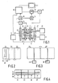
- a magnetic resonance imaging apparatus as shown in Figure 1 comprises a magnet system 2 for generating a steady, uniform magnetic field, a magnet system 4 for generating magnetic gradient fields, and power supply sources 6 and 8 for the magnet system 2 and the magnet system 4, respectively.
- a magnet coil 10 for generating an rf magnetic alternating field is connected to an rf source 12.
- a surface coil 13 is provided for the detection of magnetic resonance signals generated by the rf transmission field in an object to be examined. For reading, the coil 13 is connected to a signal amplifier 14.
- the signal amplifier 14 is connected to a phase-sensitive rectifier 16 which is connected to a central control device 18.
- the central control device 18 also controls a modulator 20 for the rf source 12, the supply source 8 for the gradient coils, and a monitor 22 for display.
- An rf oscillator 24 controls the modulator 20 as well as the phase-sensitive rectifier 16 which processes the measurement signals.
- a cooling device 26 which comprises cooling ducts 27.
- a cooling device of this kind can be constructed as a water cooling system for resistance coils or as a liquid helium dewar system for superconducting coils.
- the transmitter coil 10 which is arranged within the magnet systems 2 and 4 encloses a measurement space 28 which offers sufficient room for a patient in the case of medical diagnostic apparatus.
- the measurement space 28 there can be generated a steady magnetic field, gradient fields for position selection of slices to be imaged, and a spatially uniform rf alternating field.
- the measurement space is shielded against interference fields by a Faraday cage 29.
- a cascade of surface coils 32 so that all cross-sections of the object, in as far as covered by the measurements space 28, can be measured with a suitable signal-to-noise ratio without any displacement of the object or coils being required.
- a cascade of, for example three surface coils having a length dimension of, for example 20 cm thus enables measurement across the entire length of the measurement space.
- the coils of the cascade overlap in that direction over a distance of, for example approximately 5 cm.
- FIG. 2 A feasible cascade system is diagrammatically shown in Figure 2 which shows successive coils 32 which overlap over a distance 1 of, for example 2 cm.
- Figure 2 shows successive coils 32 which overlap over a distance 1 of, for example 2 cm.
- FIG. 3 shows a cascade of butterfly coils in accordance with the invention, the successive coils 32 being arranged so that a given overlap (1) occurs only for the wings.
- an uncoupling circuit 30 For active uncoupling, it is merely necessary to prevent any mutual influencing of the coils of the cascade itself; for this purpose there may be provided an uncoupling circuit 30.
- Such a sagittal coil configuration can also be composed of butterfly coils, in which case it may be desirable to omit the overlapping in a direction transversely of the previously mentioned direction in order to obtain an adapted geometry, for example when use is made of roof-shaped butterfly coils. Because parts of the hinges of the butterfly coils then overlap, it may be desirable to provide the aperture of the coils, that is to say the incoming and outgoing conductors, in another part of the coil.
- a feasible butterfly coil can also be formed by composing each of the wings from a separate conductor, having the same inductance L, and a common conductor in which there is included a capacitance for uncoupling the coil for transmission fields which load each of the wings to the same extent.
Landscapes
- Physics & Mathematics (AREA)
- General Physics & Mathematics (AREA)
- Condensed Matter Physics & Semiconductors (AREA)
- Chemical & Material Sciences (AREA)
- Health & Medical Sciences (AREA)
- Life Sciences & Earth Sciences (AREA)
- High Energy & Nuclear Physics (AREA)
- Analytical Chemistry (AREA)
- Biochemistry (AREA)
- General Health & Medical Sciences (AREA)
- Immunology (AREA)
- Pathology (AREA)
- Magnetic Resonance Imaging Apparatus (AREA)
Applications Claiming Priority (2)
| Application Number | Priority Date | Filing Date | Title |
|---|---|---|---|
| NL8603006 | 1986-11-27 | ||
| NL8603006A NL8603006A (nl) | 1986-11-27 | 1986-11-27 | Magnetisch resonantie apparaat met gestapeld oppervlakte spoelenstelsel. |
Publications (3)
| Publication Number | Publication Date |
|---|---|
| EP0273484A2 true EP0273484A2 (fr) | 1988-07-06 |
| EP0273484A3 EP0273484A3 (en) | 1988-07-20 |
| EP0273484B1 EP0273484B1 (fr) | 1991-08-07 |
Family
ID=19848890
Family Applications (1)
| Application Number | Title | Priority Date | Filing Date |
|---|---|---|---|
| EP87202301A Expired - Lifetime EP0273484B1 (fr) | 1986-11-27 | 1987-11-24 | Dispositif pour l'imagérie par résonance magnétique comportant un arrangement de bobines de surface empilées |
Country Status (8)
| Country | Link |
|---|---|
| US (1) | US4859947A (fr) |
| EP (1) | EP0273484B1 (fr) |
| JP (1) | JP2599404B2 (fr) |
| KR (1) | KR880006540A (fr) |
| CN (1) | CN87108042A (fr) |
| DE (1) | DE3772020D1 (fr) |
| FI (1) | FI875183A (fr) |
| NL (1) | NL8603006A (fr) |
Cited By (11)
| Publication number | Priority date | Publication date | Assignee | Title |
|---|---|---|---|---|
| WO1989005115A1 (fr) * | 1987-12-07 | 1989-06-15 | General Electric Company | Imagerie a resonance magnetique nucleaire (rmn) avec des bobines multiples de surface |
| EP0338624A1 (fr) * | 1988-04-20 | 1989-10-25 | Koninklijke Philips Electronics N.V. | Appareil à résonance magnétique muni de bobines HF découplées |
| EP0342745A2 (fr) * | 1988-05-18 | 1989-11-23 | Philips Patentverwaltung GmbH | Appareil d'examen à spin nucléaire comportant un agencement de bobines à haute fréquence |
| EP0347180A2 (fr) * | 1988-06-15 | 1989-12-20 | Btg International Limited | Structures de bobines électriques de surface |
| EP0374994A1 (fr) * | 1988-12-01 | 1990-06-27 | Koninklijke Philips Electronics N.V. | Système de bobines HF muni de plusieurs bobines superficielles |
| DE3905564A1 (de) * | 1989-02-23 | 1990-09-06 | Philips Patentverwaltung | Anordnung fuer kernspin-resonanz-untersuchungsgeraete |
| EP0390476A2 (fr) * | 1989-03-29 | 1990-10-03 | Kabushiki Kaisha Toshiba | Système de bobines pour un appareil d'imagerie par résonance magnétique |
| EP0407579A1 (fr) * | 1988-02-15 | 1991-01-16 | Yokogawa Medical Systems, Ltd | Appareil de formation d'images par resonance magnetique |
| DE4030371A1 (de) * | 1989-09-27 | 1991-05-08 | Elscint Ltd | Quadraturoberflaechenspulenanordnung |
| US5272437A (en) * | 1990-06-08 | 1993-12-21 | U.S. Philips Corporation | RF coil system in a magnetic resonance imaging apparatus |
| US5646531A (en) * | 1995-04-27 | 1997-07-08 | Siemens Aktiengesellschaft | High-frequency antenna system of a device for nuclear magnetic resonance |
Families Citing this family (14)
| Publication number | Priority date | Publication date | Assignee | Title |
|---|---|---|---|---|
| US4943775A (en) * | 1986-11-27 | 1990-07-24 | U.S. Philips Corporation | Magnetic resonance apparatus with uncoupled rf coils |
| JPH03236829A (ja) * | 1990-02-14 | 1991-10-22 | Toshiba Corp | 磁気共鳴イメージング装置 |
| US5216367A (en) * | 1990-02-21 | 1993-06-01 | Kabushiki Kaisha Toshiba | MR imaging apparatus capable of automatically selecting multiple surface coils |
| JP3110741B2 (ja) * | 1990-07-18 | 2000-11-20 | 株式会社東芝 | 磁気共鳴イメージング装置 |
| DE4226814A1 (de) * | 1992-08-13 | 1994-02-17 | Philips Patentverwaltung | Spulenanordnung für MR-Untersuchungen der Mamma |
| US5548218A (en) * | 1995-10-19 | 1996-08-20 | North Shore University Hospital Research Corporation | Flexible RF coils for MRI system |
| DE19616464A1 (de) * | 1996-04-25 | 1997-11-06 | Philips Patentverwaltung | MR-Gerät mit einer Zylinderspulenanordnung und einer Oberflächenspulenanordnung |
| US6534983B1 (en) | 2000-12-29 | 2003-03-18 | Ge Medical Systems Global Technology Company, Llc | Multi-channel phased array coils having minimum mutual inductance for magnetic resonance systems |
| US7116107B2 (en) * | 2004-09-10 | 2006-10-03 | Abitibi Geophysics Inc. | Transmitter loops in series for electromagnetic geophysical surveys |
| DE102005039380B4 (de) * | 2005-08-19 | 2009-06-10 | Siemens Ag | Oberflächenspulenanordnung für Magnetresonanztomographen |
| JP4901917B2 (ja) * | 2009-06-26 | 2012-03-21 | 中国電力株式会社 | 磁気測定装置、非破壊検査装置および磁気センサの検出コイルの配置方法 |
| EP2480906A1 (fr) * | 2009-09-21 | 2012-08-01 | Time Medical Holdings Company Limited | Réseau de bobines rf supraconductrices |
| DE102011082778B3 (de) | 2011-09-15 | 2012-11-22 | Siemens Aktiengesellschaft | Magnetresonanzspule mit überlappenden Spulenelementen, Magnetresonanzeinrichtung und Verfahren |
| DE102015218749A1 (de) * | 2015-09-29 | 2017-03-30 | Siemens Healthcare Gmbh | Adaptive MR-Lokalspule |
Citations (7)
| Publication number | Priority date | Publication date | Assignee | Title |
|---|---|---|---|---|
| EP0142077A1 (fr) * | 1983-11-08 | 1985-05-22 | Siemens Aktiengesellschaft | Dispositif à haute fréquence dans un appareil pour la résonance de spin nucléaire avec une bobine de surface |
| JPS60125550A (ja) * | 1983-12-12 | 1985-07-04 | Sanyo Electric Co Ltd | Νmr−ct用rfコイル |
| GB2159626A (en) * | 1984-03-10 | 1985-12-04 | Jeol Ltd | Nuclear magnetic resonance spectrometer or member |
| EP0164164A1 (fr) * | 1984-05-25 | 1985-12-11 | Koninklijke Philips Electronics N.V. | Appareil de résonance magnétique nucléaire avec détection par bobine de surface |
| EP0171741A2 (fr) * | 1984-08-16 | 1986-02-19 | General Electric Company | Sondes corporelles avec au moins une bobine de surface pour la spectroscopie par résonance magnétique nucléaire |
| EP0175129A2 (fr) * | 1984-08-16 | 1986-03-26 | General Electric Company | Sous-système d'antenne avec une pluralité de bobines de surface non-orthogonales pour l'imagerie par résonance magnétique nucléaire |
| EP0218290A1 (fr) * | 1985-09-25 | 1987-04-15 | Koninklijke Philips Electronics N.V. | Appareil de résonance magnétique avec détection par bobine de surface découplée |
Family Cites Families (3)
| Publication number | Priority date | Publication date | Assignee | Title |
|---|---|---|---|---|
| US4361807A (en) * | 1979-08-10 | 1982-11-30 | Picker International Limited | Nuclear magnetic resonance systems |
| US4398149A (en) * | 1981-02-02 | 1983-08-09 | Varian Associates, Inc. | NMR Probe coil system |
| NL8203934A (nl) * | 1982-10-12 | 1984-05-01 | Philips Nv | Kernspintomograaf. |
-
1986
- 1986-11-27 NL NL8603006A patent/NL8603006A/nl not_active Application Discontinuation
-
1987
- 1987-11-04 US US07/117,003 patent/US4859947A/en not_active Expired - Lifetime
- 1987-11-24 EP EP87202301A patent/EP0273484B1/fr not_active Expired - Lifetime
- 1987-11-24 DE DE8787202301T patent/DE3772020D1/de not_active Expired - Lifetime
- 1987-11-24 CN CN198787108042A patent/CN87108042A/zh active Pending
- 1987-11-24 FI FI875183A patent/FI875183A/fi not_active IP Right Cessation
- 1987-11-24 JP JP62294276A patent/JP2599404B2/ja not_active Expired - Lifetime
- 1987-11-26 KR KR870013330A patent/KR880006540A/ko not_active Application Discontinuation
Patent Citations (7)
| Publication number | Priority date | Publication date | Assignee | Title |
|---|---|---|---|---|
| EP0142077A1 (fr) * | 1983-11-08 | 1985-05-22 | Siemens Aktiengesellschaft | Dispositif à haute fréquence dans un appareil pour la résonance de spin nucléaire avec une bobine de surface |
| JPS60125550A (ja) * | 1983-12-12 | 1985-07-04 | Sanyo Electric Co Ltd | Νmr−ct用rfコイル |
| GB2159626A (en) * | 1984-03-10 | 1985-12-04 | Jeol Ltd | Nuclear magnetic resonance spectrometer or member |
| EP0164164A1 (fr) * | 1984-05-25 | 1985-12-11 | Koninklijke Philips Electronics N.V. | Appareil de résonance magnétique nucléaire avec détection par bobine de surface |
| EP0171741A2 (fr) * | 1984-08-16 | 1986-02-19 | General Electric Company | Sondes corporelles avec au moins une bobine de surface pour la spectroscopie par résonance magnétique nucléaire |
| EP0175129A2 (fr) * | 1984-08-16 | 1986-03-26 | General Electric Company | Sous-système d'antenne avec une pluralité de bobines de surface non-orthogonales pour l'imagerie par résonance magnétique nucléaire |
| EP0218290A1 (fr) * | 1985-09-25 | 1987-04-15 | Koninklijke Philips Electronics N.V. | Appareil de résonance magnétique avec détection par bobine de surface découplée |
Non-Patent Citations (1)
| Title |
|---|
| PATENT ABSTRACTS OF JAPAN, vol. 9, no. 285 (P-404)[2008], 12th november 1985; & JP-A-60 125 550 (SANYO DENKI K.K.) 04-07-1985 * |
Cited By (16)
| Publication number | Priority date | Publication date | Assignee | Title |
|---|---|---|---|---|
| WO1989005115A1 (fr) * | 1987-12-07 | 1989-06-15 | General Electric Company | Imagerie a resonance magnetique nucleaire (rmn) avec des bobines multiples de surface |
| EP0407579A1 (fr) * | 1988-02-15 | 1991-01-16 | Yokogawa Medical Systems, Ltd | Appareil de formation d'images par resonance magnetique |
| EP0407579A4 (en) * | 1988-02-15 | 1991-09-11 | Yokogawa Medical Systems, Ltd | Magnetic resonance imaging device |
| EP0338624A1 (fr) * | 1988-04-20 | 1989-10-25 | Koninklijke Philips Electronics N.V. | Appareil à résonance magnétique muni de bobines HF découplées |
| EP0342745A2 (fr) * | 1988-05-18 | 1989-11-23 | Philips Patentverwaltung GmbH | Appareil d'examen à spin nucléaire comportant un agencement de bobines à haute fréquence |
| EP0342745B1 (fr) * | 1988-05-18 | 1995-12-20 | Philips Patentverwaltung GmbH | Appareil d'examen à spin nucléaire comportant un agencement de bobines à haute fréquence |
| US5143688A (en) * | 1988-06-15 | 1992-09-01 | National Research Development Corporation | Surface electrical coil structures |
| EP0347180A3 (fr) * | 1988-06-15 | 1991-01-30 | Btg International Limited | Structures de bobines électriques de surface |
| EP0347180A2 (fr) * | 1988-06-15 | 1989-12-20 | Btg International Limited | Structures de bobines électriques de surface |
| EP0374994A1 (fr) * | 1988-12-01 | 1990-06-27 | Koninklijke Philips Electronics N.V. | Système de bobines HF muni de plusieurs bobines superficielles |
| DE3905564A1 (de) * | 1989-02-23 | 1990-09-06 | Philips Patentverwaltung | Anordnung fuer kernspin-resonanz-untersuchungsgeraete |
| EP0390476A2 (fr) * | 1989-03-29 | 1990-10-03 | Kabushiki Kaisha Toshiba | Système de bobines pour un appareil d'imagerie par résonance magnétique |
| EP0390476A3 (fr) * | 1989-03-29 | 1991-07-31 | Kabushiki Kaisha Toshiba | Système de bobines pour un appareil d'imagerie par résonance magnétique |
| DE4030371A1 (de) * | 1989-09-27 | 1991-05-08 | Elscint Ltd | Quadraturoberflaechenspulenanordnung |
| US5272437A (en) * | 1990-06-08 | 1993-12-21 | U.S. Philips Corporation | RF coil system in a magnetic resonance imaging apparatus |
| US5646531A (en) * | 1995-04-27 | 1997-07-08 | Siemens Aktiengesellschaft | High-frequency antenna system of a device for nuclear magnetic resonance |
Also Published As
| Publication number | Publication date |
|---|---|
| US4859947A (en) | 1989-08-22 |
| KR880006540A (ko) | 1988-07-23 |
| FI875183A0 (fi) | 1987-11-24 |
| DE3772020D1 (de) | 1991-09-12 |
| CN87108042A (zh) | 1988-06-08 |
| EP0273484B1 (fr) | 1991-08-07 |
| EP0273484A3 (en) | 1988-07-20 |
| FI875183A (fi) | 1988-05-28 |
| JP2599404B2 (ja) | 1997-04-09 |
| NL8603006A (nl) | 1988-06-16 |
| JPS63234957A (ja) | 1988-09-30 |
Similar Documents
| Publication | Publication Date | Title |
|---|---|---|
| US4859947A (en) | Magnetic resonance imaging apparatus comprising a stacked surface coil system | |
| EP0274773B1 (fr) | Dispositif pour l'imagerie par résonance magnétique comportant une bobine de quadrature | |
| US5898306A (en) | Single circuit ladder resonator quadrature surface RF coil | |
| US5610521A (en) | Gradient and RF coil system without RF shield | |
| US7061242B2 (en) | Magnetic resonance imaging system | |
| US5592088A (en) | Multiple-coil adopting a quadrature detection method applied thereto and a signal processing circuit employing the same in an MRI apparatus in a vertical magnetic system | |
| US5416413A (en) | Magnetic resonance examination apparatus comprising a coil system for MR mammography | |
| US5280248A (en) | Biplanar RF coil for magnetic resonance imaging systems | |
| Atalar et al. | Catheter‐tracking FOV MR fluoroscopy | |
| KR890000605B1 (ko) | 자기공명 영상장치 | |
| US4839595A (en) | Magnetic resonance apparatus with a decoupling detection surface coil | |
| Zhang et al. | Active MR guidance of interventional devices with target‐navigation | |
| CN111904420B (zh) | 磁共振断层扫描系统 | |
| EP0529730B1 (fr) | Appareil à résonance magnétique muni de bobines réceptrices decouplées | |
| IL92510A (en) | Surface coil array receiver | |
| JPH0759751A (ja) | Rfプローブ | |
| US5293126A (en) | Local transverse gradient coil | |
| EP3828573A1 (fr) | Système de gradient en forme de v pour système d'imagerie par résonance magnétique | |
| EP0815462B1 (fr) | Circuit de combinaison pour systeme de bobines de mesure rf permettant de detecter des signaux de resonnance magnetique | |
| US20040263170A1 (en) | Magnetic gradient field projection | |
| EP0338624A1 (fr) | Appareil à résonance magnétique muni de bobines HF découplées | |
| US5128615A (en) | Resonator for a magnetic resonance imaging apparatus | |
| WO2017191860A1 (fr) | Appareil d'imagerie par résonance magnétique | |
| US7279898B2 (en) | MRI RF surface coil with reduced sensitivity in proximity of conductors | |
| US6982553B2 (en) | Radio frequency coil with two parallel end conductors |
Legal Events
| Date | Code | Title | Description |
|---|---|---|---|
| PUAI | Public reference made under article 153(3) epc to a published international application that has entered the european phase |
Free format text: ORIGINAL CODE: 0009012 |
|
| PUAL | Search report despatched |
Free format text: ORIGINAL CODE: 0009013 |
|
| AK | Designated contracting states |
Kind code of ref document: A2 Designated state(s): DE FR GB IT NL |
|
| AK | Designated contracting states |
Kind code of ref document: A3 Designated state(s): DE FR GB IT NL |
|
| 17P | Request for examination filed |
Effective date: 19890117 |
|
| 17Q | First examination report despatched |
Effective date: 19900508 |
|
| GRAA | (expected) grant |
Free format text: ORIGINAL CODE: 0009210 |
|
| AK | Designated contracting states |
Kind code of ref document: B1 Designated state(s): DE FR GB IT NL |
|
| PG25 | Lapsed in a contracting state [announced via postgrant information from national office to epo] |
Ref country code: IT Free format text: LAPSE BECAUSE OF FAILURE TO SUBMIT A TRANSLATION OF THE DESCRIPTION OR TO PAY THE FEE WITHIN THE PRE;WARNING: LAPSES OF ITALIAN PATENTS WITH EFFECTIVE DATE BEFORE 2007 MAY HAVE OCCURRED AT ANY TIME BEFORE 2007. THE CORRECT EFFECTIVE DATE MAY BE DIFFERENT FROM THE ONE RECORDED.SCRIBED TIME-LIMIT Effective date: 19910807 Ref country code: NL Effective date: 19910807 |
|
| REF | Corresponds to: |
Ref document number: 3772020 Country of ref document: DE Date of ref document: 19910912 |
|
| ET | Fr: translation filed | ||
| NLV1 | Nl: lapsed or annulled due to failure to fulfill the requirements of art. 29p and 29m of the patents act | ||
| PLBE | No opposition filed within time limit |
Free format text: ORIGINAL CODE: 0009261 |
|
| STAA | Information on the status of an ep patent application or granted ep patent |
Free format text: STATUS: NO OPPOSITION FILED WITHIN TIME LIMIT |
|
| 26N | No opposition filed | ||
| REG | Reference to a national code |
Ref country code: FR Ref legal event code: CD |
|
| REG | Reference to a national code |
Ref country code: FR Ref legal event code: CD |
|
| REG | Reference to a national code |
Ref country code: GB Ref legal event code: IF02 |
|
| PGFP | Annual fee paid to national office [announced via postgrant information from national office to epo] |
Ref country code: GB Payment date: 20061127 Year of fee payment: 20 |
|
| PGFP | Annual fee paid to national office [announced via postgrant information from national office to epo] |
Ref country code: FR Payment date: 20061129 Year of fee payment: 20 |
|
| PGFP | Annual fee paid to national office [announced via postgrant information from national office to epo] |
Ref country code: DE Payment date: 20070110 Year of fee payment: 20 |
|
| REG | Reference to a national code |
Ref country code: GB Ref legal event code: PE20 |
|
| PG25 | Lapsed in a contracting state [announced via postgrant information from national office to epo] |
Ref country code: GB Free format text: LAPSE BECAUSE OF EXPIRATION OF PROTECTION Effective date: 20071123 |