EP0342708B1 - Bildsensorapparat mit einer automatischen Blendeneinrichtung für automatische Belichtungsanpassung in Abhängigkeit von Videosignalen - Google Patents
Bildsensorapparat mit einer automatischen Blendeneinrichtung für automatische Belichtungsanpassung in Abhängigkeit von Videosignalen Download PDFInfo
- Publication number
- EP0342708B1 EP0342708B1 EP89109173A EP89109173A EP0342708B1 EP 0342708 B1 EP0342708 B1 EP 0342708B1 EP 89109173 A EP89109173 A EP 89109173A EP 89109173 A EP89109173 A EP 89109173A EP 0342708 B1 EP0342708 B1 EP 0342708B1
- Authority
- EP
- European Patent Office
- Prior art keywords
- value
- exposure
- evaluating
- sampling
- evaluating value
- Prior art date
- Legal status (The legal status is an assumption and is not a legal conclusion. Google has not performed a legal analysis and makes no representation as to the accuracy of the status listed.)
- Expired - Lifetime
Links
- 230000004044 response Effects 0.000 title claims description 5
- 238000005070 sampling Methods 0.000 claims description 112
- 238000012937 correction Methods 0.000 claims description 57
- 230000008859 change Effects 0.000 claims description 22
- 230000003247 decreasing effect Effects 0.000 claims description 21
- 230000000694 effects Effects 0.000 claims description 4
- 238000013459 approach Methods 0.000 claims 4
- 230000006870 function Effects 0.000 description 21
- 230000007246 mechanism Effects 0.000 description 18
- 230000002093 peripheral effect Effects 0.000 description 14
- 230000003287 optical effect Effects 0.000 description 12
- 238000010586 diagram Methods 0.000 description 9
- 238000000034 method Methods 0.000 description 9
- 230000002159 abnormal effect Effects 0.000 description 6
- 230000008901 benefit Effects 0.000 description 5
- 230000003321 amplification Effects 0.000 description 4
- 238000012544 monitoring process Methods 0.000 description 4
- 238000003199 nucleic acid amplification method Methods 0.000 description 4
- 238000006243 chemical reaction Methods 0.000 description 2
- 230000006835 compression Effects 0.000 description 2
- 238000007906 compression Methods 0.000 description 2
- 238000007796 conventional method Methods 0.000 description 2
- 229920006395 saturated elastomer Polymers 0.000 description 2
- 238000009825 accumulation Methods 0.000 description 1
- 230000002411 adverse Effects 0.000 description 1
- 230000010354 integration Effects 0.000 description 1
- 238000012545 processing Methods 0.000 description 1
Images


Classifications
-
- H—ELECTRICITY
- H04—ELECTRIC COMMUNICATION TECHNIQUE
- H04N—PICTORIAL COMMUNICATION, e.g. TELEVISION
- H04N23/00—Cameras or camera modules comprising electronic image sensors; Control thereof
- H04N23/70—Circuitry for compensating brightness variation in the scene
- H04N23/71—Circuitry for evaluating the brightness variation
Definitions
- the present invention relates generally to an image sensing apparatus, and more particularly, to an image sensing apparatus such as a video camera having an automatic iris function of automatically adjusting exposure in response to a video signal obtained from an image sensor.
- a level of a luminance signal includes the average brightness in a picture, i.e., an absolute level of the luminance signal obtained from the image sensor and the contrast of the picture, i.e., a relative level thereof.
- the former is adjusted by an exposure adjusting operation such as adjustment of an optical iris of a lens and control of the amplification gain of a video signal, while the latter is adjusted by a gamma ( ⁇ ) correction mechanism.
- an image sensing apparatus such as a video camera having a function of automatically adjusting exposure in response to a video signal obtained from an image sensor, i.e, a so-called automatic iris function
- a conventional automatic iris system mainly includes two types: a system of mechanically adjusting exposure by adjusting an optical iris of a lens and a system of electrically adjusting exposure by adjusting the amplification factor of an amplifier for amplifying a level of a video signal obtained from an image sensor.
- Such a conventional automatic iris system has the following disadvantages: when a high luminance portion such as a light source is included in a picture, for example, the amount of stopping down of the lens is increased so that the gain of the entire picture is decreased, whereby a major object becomes insufficiently bright. Contrary to this, when the background is very dark, the amount of stopping down of the lens is decreased so that the gain of the entire picture is increased, whereby the major object becomes too bright.
- DE-A-3129356 describes the feature, that an area for exposure control is manually selected from a plurality of areas by a user and the most suitable exposure condition is realized with respect to the selected area. That means, that the exposure conditions of the non-selected areas are not taken into consideration.
- JP-A-62 110 369 An exposure correcting method for eliminating such disadvantages has been proposed in JP-A-62 110 369.
- this exposure correcting method in view of the fact that a major object is arranged in the center of a picture in many cases, the picture is divided into a central region and a peripheral region, a signal level of a video signal in each of the regions is detected as an evaluating value, and the evaluating value in the central region is weighted with respect to the evaluating value in the peripheral region (in the extreme case, the central region "1" while the peripheral region "0").
- the size of the aperture of the diaphragm and the amplification gain of the video signal are optically controlled according to the ratio of both the evaluating values, so that contribution of the central region of the picture to the determination of exposure is increased.
- a dynamic range of the present image sensor (approximately 40dB) is much smaller than a dynamic range of the luminance of an object (approximately 100dB), and a dynamic range of a display device such as a CRT (Cathode Ray Tube) (approximately 30 to 40 dB) is the same as or smaller than that of the image sensor.
- a display device such as a CRT (Cathode Ray Tube)
- gamma correction of a luminance signal is made in a circuit on the side of a camera such that overall gamma characteristics of an entire system, including all devices from an image sensor to a display device, based on photoelectric conversion characteristics (gamma characteristics) of the image sensor and nonlinear photoelectric conversion characteristics of the display device is always 1.
- the S/N (signal-to-noise) ratio is degraded, so that the luminance level frequently fluctuates due to the effect of noises, whereby exposure control becomes unstable.
- an object of the present invention is to provide an image sensing apparatus capable of decreasing overexposure and underexposure in a picture.
- Another object of the present invention is to provide an image sensing apparatus capable of performing stable exposure control without being affected by noises or the like even if a luminance level is small.
- Still another object of the present invention is to provide an image sensing apparatus capable of performing gamma correction for further correcting automatic exposure control to prevent overexposure in a high luminance portion and underexposure in a low luminance portion.
- a principal advantage of the present invention is that a target luminance level for exposure adjustment is changed according to the relation between a luminance level in a priority area and a luminance level in a non-priority area, so that overexposure and underexposure in a picture can be decreased.
- Another advantage of the present invention is that a ratio with which an exposure evaluating value in a priority area is weighted is changed according to the relation between a luminance level in the priority area and a luminance level in a non-priority area, so that overexposure and underexposure in a picture can be decreased.
- Still another advantage of the present invention is that if there is an extremely small exposure evaluating value in exposure evaluating values sampling areas, the value is previously replaced with a fixed value, so that noises in this extremely small exposure evaluating value can be prevented from affecting exposure adjustment.
- a further advantage of the present invention is that a gamma correction value is changed according to the relation between a luminance level in a priority area and a luminance area in a non-priority area, so that overexposure and underexposure in a picture can be decreased.
- Fig. 1 is a schematic block diagram showing an automatic focusing/automatic iris apparatus according to an embodiment of the present invention.
- a video camera portion 1 comprises a focusing lens 2, a focusing ring 3 for supporting this focusing lens 2 and moving the same in the direction of an optical axis, a focusing motor 4 for driving this focusing ring 3, an optical stop-down mechanism 6 for controlling exposure, an iris motor 7 for driving this stop-down mechanism 6, and an image sensing circuit 8 having a solid-state image sensor for converting light incident from an object into a video signal (referred to as image sensed video signal hereinafter).
- a luminance signal in the video signal obtained from the image sensing circuit 8 is applied to a high-pass filter (HPF) 9, a low-pass filter (LPF) 11, and a synchronizing separator circuit 12.
- HPF high-pass filter
- LPF low-pass filter
- a vertical synchronizing signal VD and a horizontal synchronizing signal HD separated from the luminance signal by the synchronizing separator circuit 12 are supplied to a switching control circuit 13 for setting sampling area.
- This switching control circuit 13 is responsive to the vertical and horizontal synchronizing signals VD and HD and a fixed output of an oscillator (not shown) serving as a clock for driving a CCD (Charge Coupled Device) for outputting a selection signal S2 to apply the same to a selecting circuit 15 in the succeeding stage so as to set a rectangular first sampling area A1 in the center of a picture, a second sampling area A2 including this sampling area A1 and having an area which is four times that of the sampling area A1, and third to sixth sampling areas A3, A4, A5 and A6 around this sampling area A2, as shown in Fig. 2.
- the switching control circuit 13 outputs a switching signal S1 for selecting outputs of the HPF 9 and the LPF 11 to apply the same to a switching circuit 14.
- the switching circuit 14 is responsive to the switching signal S1 for selecting the output of the HPF 9 in, for example, 31 fields to continue to output the same to the selecting circuit 15 in the succeeding stage, and further selecting the output of the LPF 11 only once per 32 fields to apply the same to the selecting circuit 15.
- the selecting circuit 15 is responsive to the selection signal S2 from the switching control circuit 13 for selectively applying an output of a filter selected by the switching circuit 14 to accumulating circuits 16, 17, ..., 21 corresponding to the respective sampling areas. More specifically, an output of each of filters with respect to the first sampling area A1 and an output of each of filters with respect to the second sampling area A2 are respectively applied to the accumulating circuits 16 and 17. Similarly, an output of each of filters with respect to the sampling areas A3, A4, A5 and A6 are respectively applied to the accumulating circuits 18, 19, 20 and 21.
- the accumulating circuit 16 comprises an A/D converter 22, an adder 23, and a memory circuit 24.
- the A/D converter 22 sequentially A-D converts the filter output passing through the selecting circuit 15, to apply the same to the adder 23.
- the memory circuit 24 is reset for each field.
- the memory circuit 24 holds an output of the adder 23, i.e., a value obtained by digitally converting with respect to one field, a level of a luminance signal which passed through a filter selected in the current field with respect to the first sampling area A1.
- the accumulating circuits 17, 18, ..., 21 have all the same structures as that of the accumulating circuit 16.
- a memory circuit contained in each of the accumulating circuits holds a value obtained by integrating, with respect to one field, a level of a luminance signal which passed through a filter selected in the current field with respect to each of the sampling areas.
- the integrated values held in the memory circuits are further applied to a memory circuit 25 in the succeeding stage to be collectively stored therein.
- the HPF 9 and the LPF 11 are respectively set to allow the passage of the band of 200 KHz to 2.4 MHz and the band of 0 to 2.4MHz.
- This frequency 2.4MHz is a substantially high frequency independent of a luminance signal and hence, the LFP 11 can be omitted.
- a high frequency component or a low frequency component of a luminance signal which passed through either one of the HPF 9 and the LPF 11 is digitally integrated with respect to one field, a value obtained by the integration being stored in the memory circuit 25 as an evaluating value in the current field for each sampling area.
- a value obtained by integrating a low frequency component in each of fields in which the LPF 11 is selected and a value obtained by integrating a high frequency component in each of fields in which the HPF 9 is selected out of integrated values stored in the memory circuit 25 are respectively operated by a microcomputer 26 in the succeeding stage as an exposure evaluating value for exposure control and a focus evaluating value for focus control.
- the evaluating values are processed by the microcomputer 26 in a software manner. Based on the result of this processing, the microcomputer 26 carries out an automatic focusing operation such that the focus evaluating value reaches a maximum by issuing a command to a focusing motor control circuit 27, thereby to drive the focusing motor 4 to move the focusing lens 2. In addition, the microcomputer 26 carries out automatic exposure adjustment such that the exposure evaluating value becomes a predetermined value by also issuing a command to an iris motor control circuit 28, thereby to drive the iris motor 7 to operate the stop-down mechanism 6.
- the microcomputer 26 When the video camera enters an operating state, the microcomputer 26 first executes the main routine shown in Fig. 3.
- an integrated value, corresponding to the current one field, with respect to each of the sampling areas is read in the microcomputer 26 from the memory circuit 25.
- a count value of a counter AECNT provided for carrying out the automatic focusing operation and the automatic iris operation in a time-divisional manner is decremented, that is, one is subtracted from the count value in the step 32, to determine in the step 33 whether or not the count value is zero.
- the automatic focusing operation is carried out if the count value is not zero, while the automatic iris operation is carried out only when the count value is zero.
- This automatic focusing operation is carried out by executing an automatic focusing routine (in the step 35) for holding the focusing lens 2 in an in-focus position based on a focus evaluating value which is an integrated value of the output of the HPF 9.
- the sampling area A1 is designated as a focusing area.
- the magnitude of the focus evaluating value X (1) in the current field is compared with the magnitude of the focus evaluating value X (1) in the previous field for each field, that is, every time the focus evaluating value X (1) is updated while driving the focusing motor 4 to displace the focusing lens 2 in the direction of an optical axis.
- the rotation of the focusing motor 4 is continued in the direction of increasing this focus evaluating value, to detect the peak of a mountain-like curve, 1.e., a position where the focus evaluating value reaches the maximum value.
- the position is judged to be the in-focus position, to stop the focusing motor 4 to fix the position of the focusing lens 2, thereby to complete an auto-focus operation.
- the second sampling area A2 is designated as a focusing area. Thereafter, a position where the focus evaluating value X (2) reaches the maximum value is judged to be the auto-focus position to hold the focusing lens 2 in this position, thereby to complete the auto-focus operation.
- the change of the focus evaluating value is monitored.
- the focus evaluating value greatly changes, it is determined that an object moves outside of the focusing area, to start the auto-focus operation again from the beginning.
- the monitoring operation is first carried out with respect to the first sampling area A1.
- the focus evaluating value X (1) in the first sampling area A1 greatly changes, it is also determined whether or not the focus evaluating value X (2) in the second sampling area A2 changes. If the focus evaluating value X (2) changes, resumption of the auto-focus operation is instructed. However, if this focus evaluating value X (2) does not greatly change, it is determined that a major object only moves in a transverse direction from a position represented by a dash line to a position represented by a solid line, that is, moves outside of the first sampling area A1 within the second sampling area A2, as shown in Fig. 12, to change the focusing area from the first sampling area A1 to the second sampling area A2, thereby to continue the monitoring operation.
- step 36 it is determined in the step 36 whether or not the result of subtracting one from the content of the counter AECNT is zero. If the count value is zero, a control signal is generated from the microcomputer 26 to the switching control circuit 13. The switching control circuit 13 applies the switching signal S1 for selecting the output of the LPF 11 to the switching circuit 14 upon receipt of the control signal, so that the output of the LPF 11 is selected in the step 37. When the output of the LPF 11 is thus selected, the microcomputer 26 waits until an evaluating value obtained corresponding to this selected output of the LPF 11 is read in the memory circuit 25.
- an automatic iris routine (in the step 38) which is the basis of the automatic iris operation is executed. Thereafter, the counter AECNT is returned to the initial state in the step 39 and the output of the HPF 9 is selected in the step 40. When the output of the HPF 9 is thus selected, the microcomputer 26 waits for accumulation of evaluating values in the next field.
- the initial state of the counter AECNT is a state in which an initial value "32" is set so as to calculate an exposure evaluating value based on the luminance signal which passed through the LPF 11 by one field per 32 fields.
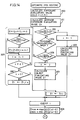
- step 33 in the main routine shown in Fig. 3 when it is determined that the count value of the counter AECNT becomes zero, that is, when 32 fields have elapsed since the auto-focus operation was started, an automatic iris routine shown in Fig. 4 is executed.
- the average value of exposure evaluating values in the entire picture given by the following expression is calculated as an average exposure evaluating value Z A in the step 201: (Z (1) + Z (2) + Z (3) + Z (4) + Z (5) + Z (6))/6
- an object evaluating value Z T is determined which represent a luminance level of this picture and is the basis of exposure control.
- the first sampling area generally designated as a focusing area in the above described automatic focusing operation is designated as a priority area for exposure control, to determine whether or not the exposure evaluating value Z (1) in the first sampling area A1 is within a predetermined allowable range with respect to the average exposure evaluating value Z A . More specifically, if it is determined in the step 202 that
- the average of exposure evaluating values within a predetermined range with respect to the average exposure evaluating value Z A that is, exposure evaluating values at which
- is the predetermined value a or less out of exposure evaluating values Z (i) (i 1 to 6) in the sampling are is calculated as the object evaluating value Z T in the step 207.
- the exposure evaluating value Z (1) in the first sampling area A1 is taken as the object evaluating value Z T .
- the ratio of both the values may be merely used.
- the exposure evaluating value is compared with the predetermined value a after logarithm compression in consideration of the fact that dynamic range of the ratio of both values is substantially wide.
- the exposure evaluating value corresponds to the first sampling area A1 is given priority.
- an extremely high luminance portion such as light source or an extremely low luminance portion such as deep green, i.e., an abnormal luminance portion exists in this first sampling area A1 and a logarithmically compressed value of the ratio of the average evaluating value Z A and the exposure evaluating value is the predetermined value a or more
- the second sampling area A2 is designated as a focusing area
- the exposure evaluating value Z (2) in this sampling area is given priority.
- the average of exposure evaluating values in sampling areas where no abnormal luminance portions exist is judged to be the object evaluating value, and the corresponding sampling areas are taken as the basis of the automatic iris operation.
- Step 210 the logarithm LOG (Zmax/Z T ) of the ratio of the maximum evaluating value Zmax to the object evaluating value Z T and the logarithm LOG (Z T /Zmin) of the ratio of the object evaluating value Z T to the minimum evaluating value Zmin are calculated, and the difference therebetween, i.e., LOG (Z T /Zmin) - LOG (Zmax/Z T ) is derived as a light and darkness determining value D.
- This light and darkness determining value D becomes a parameter determining whether a major object for determining the object evaluating value Z T is relatively bright or dark in a picture. If the major object is bright so that the object evaluating value Z T is relatively large, the logarithm LOG (Z T /Zmin) which is the first term is increased and the logarithm LOG (Zmax/Z T ) which is the second term is decreased, so that the light and darkness determining value D becomes larger. Contrary to this, if the object evaluating value Z T is relatively small, the first term is decreased and the second term is increased, so that the light and darkness determining value D becomes smaller.
- the reason why the logarithm of the ratio of the evaluating values is used in calculating this light and darkness determining value D is that recognition of brightness in vision of a human being is generally achieved by noting that brightness in vision is linearly changed as luminance level of an actual object is exponentially increased, for example, increased by two times, four times and eight times in that order.
- the determining value D is - b or less, it is determined that the luminance of the object in the picture is relatively low, to respectively set the upper limit Z U and the lower limit Z L to W and w in the step 215. It is assumed in advance that the relations U ⁇ V ⁇ W and u ⁇ v ⁇ w respectively hold between the upper limits and between the lower limits. Accordingly, a target range, corresponding to relative brightness in the picture, of the object evaluating value Z T is set.
- the above described predetermined value b is a limit value taken when the luminance level of the major object is visually recognized to be significantly higher or significantly lower than the luminous level of the entire picture, which is experimentally found in advance.
- the object evaluating value Z T , the upper limit Z U and the lower limit Z L of the target value are compared. If the relation Z U > Z T > Z L holds, it is determined that proper exposure is obtained, to maintain the iris motor 7 for driving the optical stop-down mechanism 6 in the stopped state to maintain the present aperture of the diaphragm. On the other hand, if the object evaluating value Z T is larger than the upper limit Z U , it is determined that the overexposure occurs, to drive the iris motor 7 in the direction in which the diaphragm of the stop-down mechanism 6 is closed by one step in the step 219.
- the iris motor 7 is constituted by a stepping motor.
- the gain of an AGC amplifier 301 (see Fig. 1) for amplifying an image sensed video signal is fixed to a constant value (including zero) (this state is referred to as the off state of an AGC operation) in the step 222.
- the AGC amplifier 301 is operated in the step 221.
- the gain of the AGC amplifier 301 is increased or decreased such that an output thereof attains a constant level depending on whether a level of the inputted image sensed video signal is large or small (this state is referred to as the on state of the AGC operation).
- the opened state of the optical stop-down mechanism 6 can be detected by monitoring the amount of all rotation (the number of all steps) of the iris motor 7 and mechanically detecting an operation of the optical stop-down mechanism 6 itself.
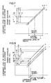
- Figs. 7 to 9 are diagrams showing characteristics of an exposure adjusting operation carried out by finely changing the upper limit and the lower limit of a target luminance level depending on whether the the light and darkness determining value D is large or small as described above.
- the object evaluating value Z T is obtained from the first sampling area A1 which is a focusing area and the major object exists in this first sampling area A1, whereby the luminance level of the major object corresponds to the object evaluating value Z T .
- the axis of abscissa represents an actual luminance level, before exposure adjustment, of the entire picture including the major object and the background, where a luminance region corresponding to the entire picture is represented by L (represented by an arrow in the drawings) and particularly, the actual luminance level of the major object is represented by ⁇ .
- the axis of ordinate represents a luminance level of an image sensed video signal after exposure adjustment by the stop-down mechanism 6 and the AGC amplifier 301, where a proper exposure range M which is an allowable range where an image superior in quality can be recognized in vision of a human being is represented by an arrow.
- Fig. 7 shows a case in which the relation
- Fig. 8 shows a case in which the relation D ⁇ - b holds, and the actual luminance level ⁇ of the major object is located in the slightly lower portion in the region L, that is, the major object is relatively dark.
- Fig. 9 shows a case in which the relation D > + b holds, and the actual luminance level ⁇ of the major object is located in the slightly higher portion in the region L, that is, the major object is relatively bright.
- P represents a region of a luminance level of the image sensed video signal after exposure adjustment with respect to the entire picture in employing a conventional method of carrying out exposure adjustment based on only an average luminance level of the entire picture, the actual luminance level of the entire picture and the luminance level of the image sensed video signal in this case having a relation represented by a straight line p.
- An average value AV of this region P (a middle point of P) is matched with an optimum value m which is a middle point of the proper exposure range M so that the proper exposure range M can be located in the center of the region P with respect to the entire picture.
- m is a middle point of the proper exposure range M
- the luminance level of the image sensed video signal with respect to the major object is t1, which is outside of the proper exposure range M, so that overexposure or underexposure occurs with respect to the major object.
- Q represents a region of a luminance level of the image sensed video signal with respect to the entire picture in employing a conventional method of matching with the optimum value m the luminance level of the image sensed video signal with respect to the major object or a luminance level of the image sensed video signal with respect to an area including this major object, the actual luminance level of the entire picture and the luminance level of the image sensed video signal in this case having a relation represented by a straight line q.
- this method exposure most suitable for the major object is obtained.
- a luminance level of another portion such as the background is greatly outside of the proper exposure range M, so that the picture includes a dim portion or a portion saturated with white.
- R represents a region of a luminance level of the image sensed video signal with respect to the entire picture obtained by the method according to the present embodiment, the actual luminance level of the entire picture and the luminance level of the image sensed video signal after exposure adjustment having a relation represented by a straight line r.
- this straight line r is shifted in an up and down direction to finely change a target luminance level, as described below.
- the upper limit and the lower limit of the target value are respectively set to V and v, to operate the stop-down mechanism 6 such that the object evaluating value Z T corresponding to the sampling area including the major object is located between the upper limit V and the lower limit v.
- a luminance level t3 of the image sensed video signal with respect to the major object is matched with the optimum value m as in the above described region Q, and the proper exposure range M is located in almost the center of the region R of the luminance level of the image sensed video signal with respect to the entire picture, so that proper exposure adjustment is carried out.
- the upper limit Z U and the lower limit Z L of the target value for controlling the object evaluating value Z T are respectively changed to W and w smaller than V and v, to operate the stop-down mechanism 6 such that the object evaluating value Z T is located between the upper limit Z U and the lower limit Z L .
- the upper limit Z U and the lower limit Z L of the target value for controlling the object evaluating value Z T are respectively changed to U and u larger than V and v, to operate the stop-down mechanism 6 such that the straight line r shown in Fig. 8 is shifted upward. Consequently, as shown in Fig. 9, the luminance level of the image sensed video signal with respect to the major object is located in the vicinity of the upper limit of the proper exposure range M and the region R of the luminance level of the image sensed video signal with respect to the entire picture is matched with the proper exposure range M to the utmost. As a result, proper exposure considerably superior in quality in vision is obtained with respect to the major object and a luminance level of another picture is not greatly outside of the proper exposure range M, so that a good picture is obtained as a whole.
- the contrast ⁇ of the picture is calculated as the ratio of the maximum value Zmax to the minimum value Zmin in the exposure evaluating values.
- the above described contrast ⁇ is substituted in a decreasing function f ( ⁇ ) previously set, thereby to perform an operation so as to change a gamma ( ⁇ ) for correction as the most suitable value.
- the gain of the AGC amplifier 301 is not fixed to a constant value and thus, the ordinary AGC operation is enabled in the step 221 in the flowchart of Fig. 5 because the luminance of the object is extremely low, the gamma correction value ⁇ is decreased by a predetermined amount d1 to compress the contrast of the picture in the step 233. Consequently, a signal level of the object of low luminance is substantially raised.
- the gamma correction value ⁇ is decreased by a predetermined value d2 to compress the contrast of the picture in the step 235.
- the optical stop-down mechanism 6 when the relation D ⁇ - b holds and the luminance level of the major object, i.e., the object evaluating value is relatively significantly lower then the luminance level of the entire picture, exposure adjustment is carried out by the optical stop-down mechanism 6, so that the luminance level of the major object is located in the vicinity of the lower limit of the proper exposure range M and the proper exposure range M is located in the center of the luminance region corresponding to the entire picture as represented by R shown in Fig. 8, whereby the proper exposure is obtained relative to the major object as well as the entire picture.
- a high luminance region r0 in the region R after exposure adjustment remains outside of the proper exposure range M.
- the straight line r is changed to a curve r′ so that the luminance region corresponding to the entire picture is changed from R to R′, as shown in Fig. 10.
- the luminance region R′ corresponding to the entire picture can be almost matched with the proper exposure range M while locating the luminance level of the major object in the vicinity of the lower limit of the proper exposure range M, to further correct exposure adjustment carried out by the optical stop-down mechanism 6 so that more proper exposure is achieved.
- the luminance region R ⁇ corresponding to the entire picture can be almost matched with the proper exposure range M while locating the luminance level of the major object in the vicinity of the upper limit of the proper exposure range M, to further correct exposure adjustment carried out by the optical stop-down mechanism 6 so that more proper exposure is achieved.
- overexposure in the high luminance portion and underexposure in the low luminance portion can be prevented.
- the gamma correction value ⁇ in the current field thus determined is supplied to a gamma correcting circuit 302 (see Fig. 1). If this gamma correction value ⁇ is greatly different from a gamma correction value ⁇ 0 previously determined, gamma correction is made at a stroke, so that the picture is rather unclear. Therefore, the gamma correction value must be gradually changed.
- the gamma correction value ⁇ in the current field and the gamma correction value ⁇ 0 previously determined, i.e., determined 32 fields before are compared with each other. If the gamma correction value in the current field is larger, the gamma correction value is increased by the magnitude d ⁇ corresponding to one step in the step 241. Contrary to this, if the gamma correction value ⁇ 0 previously determined is larger, the gamma correction value is decreased by the magnitude d ⁇ corresponding to one step in the step 242. In this case, the magnitude d corresponding to one step is set by dividing the difference between the maximum value and minimum value which the gamma correction value ⁇ can take into n (n: natural number) equal divisions. In other words, the gamma correction value ⁇ is changed in n steps.
- the directions of the changes of the gamma correction values previously determined and in the current field are compared with each other based on the state of a flag SX in the steps 237 and 238. If both are the same, the program skips over the steps 239 and 240, to proceed to the steps 241 and 242.
- the gamma correction values are changed only when the difference
- the manner of change of the gamma correction value is adapted to have hysteresis.
- the gamma correction value ⁇ 0 is initialized immediately after the power supply is turned on.
- a control signal corresponding to the gamma correction value thus determined is inputted to the gamma correcting circuit 302 connected to the succeeding stage of the AGC amplifier 301 as a control signal.
- the amplification factor is changed according to an input level of an image sensed video signal based on this gamma correction value, so that the most suitable gamma correction is performed.
- suitable brightness is obtained over the entire picture even with respect to an object having a high picture contrast.
- the image sensed video signal subjected to gamma correction by the gamma correcting circuit 302 is displayed on a CRT or is recorded by a VTR (Video Tape Recorder), which are not shown.
- the step 201 and the subsequent steps in the flowchart are carried out in the above described manner, so that the change of the exposure evaluating value frequently caused by the effect of noises is prevented from affecting exposure control and gamma correction.
- the limit value Pm is a value at which it is recognized that the change of the exposure evaluating value caused by noises becomes significant when the luminance level is extremely small so that exposure control starts to be adversely affected
- Fig. 14 is a flowchart showing an automatic iris operation according to another embodiment carried out in consideration of this respect.
- the same portions as those in Fig. 4 have the same reference numerals and hence, the description thereof is not repeated.
- object evaluating value calculating routine 300 or 301 obtained in consideration of the above described respect is executed.
- of the ratios of the exposure evaluating values Z (1) and Z (2) to the average exposure evaluating value Z A used in the steps 202 and 205 and predetermined values b0 and c0 are respectively determined in the steps 310 and 311.
- the relations a > b0 > c0 holds among the predetermined values a, b0 and c0.
- the exposure evaluating values Z (1), Z (2), ..., Z (6) corresponding to respective sampling areas are substituted in a function f to calculate the object evaluating value Z T .
- the exposure evaluating values Z (1), Z (2), ..., Z (6) are substituted in a function g to calculate the object evaluating value Z T .
- the exposure evaluating value Z(1) is substituted in a function h to calculate the object evaluating value Z T .
- has the property of being larger as the difference in luminance between sampling areas becomes larger.
- the object value Z T is calculated using the function f if the difference in luminance is extremely large, using the function g if the difference in luminance is slightly smaller, and using the function h if there is little difference in luminance.
- the effect of the exposure evaluating value Z (1) in the object evaluating value Z T can be decreased. More specifically, the priority of the first sampling area A1 which is a priority area in a calculation of the object evaluating value Z T is decreased.
- the second sampling area A2 is designated as a priority area in the step 205
- functions for calculating the object evaluating value Z T are switched to h, g and f in that order as the difference in luminance between sampling areas is larger in the calculating routine 301 of the object evaluating value Z T .
- the calculating routine 301 is shown in almost the same flowchart as that of the routine 300. However, the exposure evaluating values Z (1) and Z (2) in the equations are replaced with each other.
- the equations are switched only when the conditions in the steps 310 and 311 are satisfied, for example, over continuous three fields, unstable exposure control is mitigated.
- and the ratio of weighting of each of the exposure evaluating values Z (1), Z (2), ..., Z (6) in sampling areas are respectively shown in Figs. 16 and 17. More specifically, the ratio of weighting of each of the exposure evaluating values in the object evaluating value Z T is changed in steps utilizing the predetermined values b0 and c0 as threshold values, according to three regions among the threshold values.
- a routine shown in Fig. 18 is executed instead of the object evaluating value calculating routine shown in Fig. 15.
- the calculating routine shown in Fig. 18 is executed.
- the change of the object evaluating value Z T can be made smoother according to the change of the picture, so that the picture can be stable.
- a target luminance level for exposure adjustment is changed, a ratio with which an exposure evaluating value corresponding to a priority area is weighted is changed, or a gamma correction value is changed according to the relation between luminance levels in the priority area and a non-priority area, so that overexposure and underexposure in a picture can be decreased.
- the value is previously replaced with a fixed value, so that exposure control can be prevented from being affected by noises or the like.
Landscapes
- Engineering & Computer Science (AREA)
- Multimedia (AREA)
- Signal Processing (AREA)
- Studio Devices (AREA)
- Automatic Focus Adjustment (AREA)
- Exposure Control For Cameras (AREA)
Claims (10)
- Bildsensorapparat zur automatischen Belichtungsanpassung an ein Objekt, mit:
einer Bildsensoreinrichtung (2, 8) mit einer Linse und einem Bildsensor zum Erzeugen eines Videosignals in Abhängigkeit von vom Objekt auftreffendem Licht;
einer Einrichtung (6, 7, 301) zum Ändern der Belichtung des Objekts, einer Einrichtung zum Einstellen einer Vielzahl von Abtastbereichen, die auf dem abgetasteten Bild, in zeitteilender Art und Weise des Videosignals unterteilt sind;
einer Belichtungsauswertungswert-Detektoreinrichtung (11, 16-21) zum Detektieren des Pegels eines Helligkeitssignals in einem Videosignal in jedem der vielen Abtastbereiche, um dasselbe als einen Belichtungsauswertungswert im entsprechenden Abtastbereich zu liefern;
einer Objekt-Auswertungswert-Recheneinrichtung (26) zum automatischen Wählen eines Bereiches im Mittelpunkt des bildabgetasteten Bildes aus der Vielzahl Abtastbereiche als vorrangigen Bereich für die Belichtungssteuerung, zum Bewerten des Belichtungsauswertungswertes im gewählten Abtastbereich mit einem vorbestimmten Verhältnis bezogen auf die Belichtungsauswertungswerte in anderen Abtastbereichen als dem vorrangig gewählten Abtastbereich und zum Berechnen eines Objekt-Auswertungswertes, der die Belichtung des gesamten bildabgetasteten Bildes basierend auf den Belichtungsauswertungswerten repräsentiert;
einer Belichtungs-Steuereinrichtung (26, 28) zum Steuern der Belichtungs-Änderungs-Einrichtung zum Steuern der Belichtungsänderungseinrichtung, dergestalt, daß sich der Objekt-Auswertungswert an einen vorbestimmten Zielhelligkeitspegel annähert, der erreicht wird, wenn korrekte Belichtungsbedingungen erzielt sind;
Mittel zum Ändern des Bewertungsverhältnisses, so daß sich das Bewertungsverhältnis im vorrangigen Bereich einen Mittelwert der Belichtungsauswertungswerte in allen Abtastbereichen annähert, während das Bewertungsverhältnis in jedem Bereich gleichgemacht wird, wenn die Belichtungsauswertungswerte in dem vorrangigen Bereich vom Mittelwert entweder in Richtung einer Erhöhung oder in Richtung einer Verringerung abweichen. - Bildsensorapparat nach Anspruch 1,
dadurch gekennzeichnet, daß die Mittel (26) zum Ändern des Bewertungsquotienten den Zielhelligkeitspegel ändern gemäß der Beziehung zwischen dem Objekt-Auswertungswert und den Belichtungsauswertungswerten in den anderen Abtastbereichen als dem als vorrangig gewählten Abtastbereich, während der Zielhelligkeitspegel erhöht wird, wenn der Objektauswertungswert größer als die Belichtungsauswertungswerte in den anderen Abtastbereichen ist, während der Zielhelligkeitspegel gesenkt wird, wenn der Objektauswertungswert kleiner als die Belichtungsauswertungswerte in den anderen Abtastbereichen ist. - Bildsensorapparat nach Anspruch 2,
dadurch gekennzeichnet, daß der Zielhelligkeitspegel einen Bereich hat, der durch die obere Grenze und die untere Grenze definiert ist, und die Mittel zum Ändern des Zielhelligkeitspegels Mittel zum Ändern der oberen Grenze und der unteren Grenze des Zielhelligkeitspegels gemäß der Beziehung zwischen dem Maximalwert und dem Minimalwert der Belichtungsauswertungswerte und dem Objektauswertungswert, aufweisen. - Bildsensorapparat nach Anspruch 1,
dadurch gekennzeichnet, daß die Mittel (26) zum Ändern des Verhältnisses Mittel zum stufenweisen Ändern des Verhältnisses in Übereinstimmung mit der Beziehung zwischen dem Belichtungs-Auswertungswert im als vorrangig gewählten Abtastbereich und dem Mittel der Belichtungsauswertungswerte in allen Abtastbereichen, aufweisen. - Bildsensorapparat nach Anspruch 1,
dadurch gekennzeichnet, daß die Mittel (26) zum Ändern des Verhältnisses Mittel zum fortlaufenden Ändern des Verhältnisses in Übereinstimmung mit der Beziehung zwischen dem Belichtungs-Auswertungswert im als vorrangig ausgewählten Abtastbereich und dem Mittel der Belichtungsauswertungswerte in allen Abtastbereichen, aufweist. - Bildabtastbereich nach Anspruch 1,
dadurch gekennzeichnet, daß die Mittel (26) den Belichtungsauswertungswert, welcher von der Belichtungsauswertungswert-Recheneinrichtung zugeführt ist, mit einem vorbestimmten Referenzwert vergleichen, um den Belichtungsauswertungswert durch einen vorbestimmten Fixwert zu ersetzen, wenn der Belichtungsauswertungswert kleiner als der Referenzwert ist, und
die Belichtungssteuereinrichtung (26, 28) die Belichtungsänderungsmittel so steuert, daß sich der Objektauswertungswert einem vorbestimmten Zielhelligkeitswert annähert. - Bildsensorapparat nach Anspruch 6,
dadurch gekennzeichnet, daß der Fixwert basierend auf einem Wert, bei dem die Wirkung der Änderung des Belichtungsauswertungswertes, verursacht durch Rauschen bei der Belichtungssteuerung erkannt werden kann, bestimmt wird. - Bildsensorapparat zur automatischen Belichtungsanspassung an ein Objekt und automatischen Durchführung der Gamma-Korrektur eines Videosignals, mit:
einer Bildsensoreinrichtung (2, 8) mit einer Linse und einem Bildsensor zum Erzeugen eines Videosignals in Abhängigkeit von von dem Objekt auftreffendem Licht,
einer Einrichtung (6, 7, 301) zum Ändern der Belichtung des Objektes;
einer Einrichtung (12, 13, 15) zum Einstellen einer Vielzahl von Abtastbereichen, die an einem bildabgetasteten Bild unterteilt sind, in zeitteilender Art und Weise des Videosignals;
einer Belichtungsauswertungswert-Detektoreinrichtung (11, 16, 21) zum Detektieren des Pegels eines Helligkeitssignals in einem Videosignal in jedem der Vielzahl von Abtastbereichen, um dasselbe als Belichtungs-Auswertungswert im entsprechenden Abtastbereich zu liefern;
einer Objekt-Auswertungswert-Recheneinrichtung (26) zum Wählen wenigstens eines der Vielzahl von Abtastbereichen als vorrangigen Bereich für die Belichtungssteuerung und Berechnen eines Objekt-Auswertungswertes, der die Belichtung des gesamten bildabgetasteten Bildes, basierend auf einem Belichtungsauswertungswert in dem gewählten Abtastbereich, repräsentiert,
einer Belichtungssteuereinrichtung (26, 28) zum Steuern der Belichtungsänderungseinrichtung dergestalt, daß der ObjektAuswertungswert sich einem vorbestimmten Zielhelligkeitspegel annähert,
Mitteln (26) zum Bestimmen eines Gamma-Korrekturwertes zur Durchführung der Gamma-Korrektur des Videosignals in Übereinstimmung mit dem Gamma-Korrekturwert; und
Mitteln (26) zum Ändern des Gammakorrekturwertes in Übereinstimmung mit der Beziehung zwischen dem Objektauswertungswert und den Belichtungsauswertungswerten in den anderen Abtastbereichen als dem als vorrangig ausgewählten Abtastbereich. - Bildsensorapparat nach Anspruch 8,
dadurch gekennzeichnet, daß weiterhin Mittel (26) zum Bestimmen eines Gammakorrekturwertes, basierend auf dem Wert, welcher den Kontrast anzeigt, vorgesehen sind. - Bildsensorapparat nach Anspruch 8,
weiterhin gekennzeichnet durch Mittel (26) zum Berechnen eines Wertes, der den Kontrast des bildabgetasteten Bildes basierend auf dem Belichtungsauswertungswert, welcher von der Belichtungsauswertungswert-Detektoreinrichtung zugeführt worden ist, und
Mitteln (26) zum Bestimmen eines Gamma-Korrekturwertes basierend auf dem Wert, welcher den Kontrast angibt, um eine Gammakorrektur des Videosignals in Übereinstimmung mit dem Gammakorrekturwert durchzuführen.
Applications Claiming Priority (10)
| Application Number | Priority Date | Filing Date | Title |
|---|---|---|---|
| JP124534/88 | 1988-05-20 | ||
| JP124533/88 | 1988-05-20 | ||
| JP12453488 | 1988-05-20 | ||
| JP12453388 | 1988-05-20 | ||
| JP63150575A JP2645859B2 (ja) | 1988-05-20 | 1988-06-17 | 撮像装置 |
| JP15057488 | 1988-06-17 | ||
| JP150575/88 | 1988-06-17 | ||
| JP193027/88 | 1988-08-02 | ||
| JP63193027A JP2547619B2 (ja) | 1988-05-20 | 1988-08-02 | 撮像装置 |
| JP150574/88 | 1988-11-18 |
Publications (3)
| Publication Number | Publication Date |
|---|---|
| EP0342708A2 EP0342708A2 (de) | 1989-11-23 |
| EP0342708A3 EP0342708A3 (en) | 1990-12-27 |
| EP0342708B1 true EP0342708B1 (de) | 1995-01-11 |
Family
ID=27527036
Family Applications (1)
| Application Number | Title | Priority Date | Filing Date |
|---|---|---|---|
| EP89109173A Expired - Lifetime EP0342708B1 (de) | 1988-05-20 | 1989-05-22 | Bildsensorapparat mit einer automatischen Blendeneinrichtung für automatische Belichtungsanpassung in Abhängigkeit von Videosignalen |
Country Status (5)
| Country | Link |
|---|---|
| US (1) | US4969045A (de) |
| EP (1) | EP0342708B1 (de) |
| AU (1) | AU609610B2 (de) |
| CA (1) | CA1309166C (de) |
| DE (1) | DE68920475T2 (de) |
Cited By (1)
| Publication number | Priority date | Publication date | Assignee | Title |
|---|---|---|---|---|
| EP3900320A1 (de) * | 2018-12-19 | 2021-10-27 | Valeo Comfort and Driving Assistance | Bildaufnahmevorrichtung und dazugehöriges system zur überwachung eines fahrers |
Families Citing this family (114)
| Publication number | Priority date | Publication date | Assignee | Title |
|---|---|---|---|---|
| JP4802350B2 (ja) * | 1998-03-12 | 2011-10-26 | ソニー株式会社 | 表示装置 |
| AU607033B2 (en) * | 1988-01-12 | 1991-02-21 | Sanyo Electric Co., Ltd. | Auto iris/gamma correction apparatus for making automatic exposure adjustment and/or automatic gamma correction in response to video signal and image sensing apparatus comprising such auto iris/gamma correction apparatus |
| KR940001483B1 (ko) * | 1989-03-29 | 1994-02-23 | 가부시끼가이샤 히다찌세이사꾸쇼 | 촬상장치 및 그 노출 제어방법 및 장치 |
| US5049997A (en) * | 1989-04-10 | 1991-09-17 | Fuji Photo Film Co., Ltd. | Video camera exposure control method and apparatus for preventing improper exposure due to changing object size or displacement and luminance difference between the object and background |
| US5040072A (en) * | 1989-04-21 | 1991-08-13 | Casio Computer Co., Ltd. | Automatic exposure control system for electronic camera |
| US5051833A (en) * | 1989-04-28 | 1991-09-24 | Casio Computer Co., Ltd. | Camera apparatus capable of freely setting objective area within viewed subject |
| JPH031772A (ja) * | 1989-05-30 | 1991-01-08 | Sony Corp | 撮像装置 |
| US5111301A (en) * | 1989-06-28 | 1992-05-05 | Sanyo Electric Co., Ltd. | Automatic exposure adjusting apparatus for automatically adjusting exposure by fuzzy inference |
| EP0409161B1 (de) * | 1989-07-18 | 2000-10-11 | Fuji Photo Film Co., Ltd. | Verfahren und Einrichtung zur Steuerung der Belichtungsänderungen einer Videokamera |
| JP3143110B2 (ja) * | 1989-07-24 | 2001-03-07 | 株式会社リコー | 画像入力装置 |
| US5249058A (en) * | 1989-08-08 | 1993-09-28 | Sanyo Electric Co., Ltd. | Apparatus for automatically focusing a camera lens |
| JP2974339B2 (ja) * | 1989-09-20 | 1999-11-10 | キヤノン株式会社 | 自動焦点調節装置 |
| US5164833A (en) * | 1989-11-15 | 1992-11-17 | Konica Corporation | Electronic viewfinder |
| US5065443A (en) * | 1989-12-04 | 1991-11-12 | Allen-Bradley Company, Inc. | Image processor with illumination variation compensation |
| JP2899031B2 (ja) * | 1989-12-28 | 1999-06-02 | キヤノン株式会社 | 自動露出制御装置 |
| DE69121930T2 (de) * | 1990-02-08 | 1997-04-03 | Canon Kk | Bildaufnahmevorrichtung |
| JP2822256B2 (ja) * | 1990-02-15 | 1998-11-11 | ソニー株式会社 | ビデオカメラの露光補正装置 |
| DE69127112T2 (de) * | 1990-02-28 | 1998-03-05 | Sanyo Electric Co | Automatisches Fokussierungsgerät zur automatischen Fokusanpassung in Abhängigkeit von Videosignalen |
| US5223935A (en) * | 1990-04-02 | 1993-06-29 | Casio Computer Co., Ltd. | Electronic camera with automatic exposure control |
| US6249317B1 (en) * | 1990-08-01 | 2001-06-19 | Minolta Co., Ltd. | Automatic exposure control apparatus |
| US5264940A (en) * | 1990-10-08 | 1993-11-23 | Olympus Optical Co., Ltd. | Image sensing apparatus having exposure level and dynamic range control circuit |
| US6072526A (en) * | 1990-10-15 | 2000-06-06 | Minolta Co., Ltd. | Image sensing device that can correct colors corresponding to skin in a video signal |
| US5920349A (en) * | 1990-11-05 | 1999-07-06 | Canon Kabushiki Kaisha | Image pickup device |
| US5185671A (en) * | 1991-06-21 | 1993-02-09 | Westinghouse Electric Corp. | Adaptive control of an electronic imaging camera |
| US5694168A (en) * | 1991-09-04 | 1997-12-02 | Fuji Photo Film Co., Ltd. | Auto focus control device and method including selecting a zone for detecting an evaluative value for focusing in accordance with photographing direction |
| US5455685A (en) * | 1991-09-04 | 1995-10-03 | Fuji Photo Film Co., Ltd. | Video camera exposure control apparatus for controlling iris diaphragm and automatic gain control operating speed |
| JP3209761B2 (ja) * | 1991-09-24 | 2001-09-17 | キヤノン株式会社 | 焦点調節装置 |
| JPH05167911A (ja) * | 1991-12-12 | 1993-07-02 | Sony Corp | 信号処理装置 |
| JP2725933B2 (ja) * | 1992-01-31 | 1998-03-11 | 三洋電機株式会社 | オートフォーカス装置 |
| JP2996806B2 (ja) * | 1992-06-11 | 2000-01-11 | キヤノン株式会社 | カメラ、自動焦点調節装置及び焦点調節方法 |
| JP3106006B2 (ja) * | 1992-06-24 | 2000-11-06 | キヤノン株式会社 | 電子スチルカメラ |
| JP3386495B2 (ja) * | 1992-09-14 | 2003-03-17 | 富士写真フイルム株式会社 | ディジタル電子スチル・カメラおよびその制御方法 |
| DE69421121T2 (de) * | 1993-06-30 | 2000-04-13 | Nec Corp., Tokio/Tokyo | Farbvideokamera mit Gradationsverbesserung des dunklen Signalpegels |
| US5745808A (en) * | 1995-08-21 | 1998-04-28 | Eastman Kodak Company | Camera exposure control system using variable-length exposure tables |
| US5745175A (en) * | 1995-10-02 | 1998-04-28 | Flashpoint Technologies, Inc. | Method and system for providing automatic focus control for a still digital camera |
| JPH09284784A (ja) * | 1996-04-12 | 1997-10-31 | Sony Corp | カラー撮像装置 |
| CN1221488A (zh) | 1996-05-10 | 1999-06-30 | 应用科学模拟公司 | 亮度优先彩色检测器 |
| US6069714A (en) | 1996-12-05 | 2000-05-30 | Applied Science Fiction, Inc. | Method and apparatus for reducing noise in electronic film development |
| JP3107760B2 (ja) * | 1996-12-25 | 2000-11-13 | 松下電器産業株式会社 | 露光量制御装置 |
| US6442301B1 (en) | 1997-01-06 | 2002-08-27 | Applied Science Fiction, Inc. | Apparatus and method for defect channel nulling |
| US6380539B1 (en) | 1997-01-30 | 2002-04-30 | Applied Science Fiction, Inc. | Four color trilinear CCD scanning |
| US6017688A (en) | 1997-01-30 | 2000-01-25 | Applied Science Fiction, Inc. | System and method for latent film recovery in electronic film development |
| AU2563199A (en) | 1998-02-04 | 1999-08-23 | Applied Science Fiction, Inc. | Multilinear array sensor with an infrared line |
| TW369623B (en) | 1998-02-23 | 1999-09-11 | Estman Kodak Company | Progressive area scan in electronic film development |
| EP1062636A1 (de) | 1998-03-13 | 2000-12-27 | Applied Science Fiction, Inc. | Verfahren zur bildfehlerkorrektur |
| US6594041B1 (en) | 1998-11-20 | 2003-07-15 | Applied Science Fiction, Inc. | Log time processing and stitching system |
| US6437358B1 (en) | 1999-02-04 | 2002-08-20 | Applied Science Fiction, Inc. | Apparatus and methods for capturing defect data |
| US6781620B1 (en) | 1999-03-16 | 2004-08-24 | Eastman Kodak Company | Mixed-element stitching and noise reduction system |
| AU6202100A (en) | 1999-06-29 | 2001-01-31 | Applied Science Fiction, Inc. | Slot coating device for electronic film development |
| WO2001013174A1 (en) | 1999-08-17 | 2001-02-22 | Applied Science Fiction, Inc. | Method and system for using calibration patches in electronic film processing |
| CN1375161A (zh) | 1999-09-16 | 2002-10-16 | 应用科学小说公司 | 适用于改变数字图像中缺陷的方法和系统 |
| WO2001027688A2 (en) | 1999-10-08 | 2001-04-19 | Applied Science Fiction, Inc. | System and method for correcting defects in digital images through selective fill-in from surrounding areas |
| WO2001028226A1 (en) | 1999-10-08 | 2001-04-19 | Applied Science Fiction | Method and apparatus for differential illumination image-capturing and defect handling |
| US6924911B1 (en) | 1999-10-12 | 2005-08-02 | Eastman Kodak Company | Method and system for multi-sensor signal detection |
| US6711302B1 (en) | 1999-10-20 | 2004-03-23 | Eastman Kodak Company | Method and system for altering defects in digital image |
| US6734913B1 (en) | 1999-10-28 | 2004-05-11 | Hewlett-Packard Development Company, L.P. | Method of automatically adjusting exposure in a shutterless digital camera |
| WO2001045042A1 (en) | 1999-12-17 | 2001-06-21 | Applied Science Fiction, Inc. | Method and system for selective enhancement of image data |
| DE60022975T2 (de) * | 1999-12-21 | 2006-07-06 | Koninklijke Philips Electronics N.V. | Fotoapparat mit automatischem Fokussierungsgerät |
| US6683995B2 (en) | 1999-12-23 | 2004-01-27 | Eastman Kodak Company | Method and apparatus for correcting large defects in digital images |
| US7164511B2 (en) * | 1999-12-29 | 2007-01-16 | Eastman Kodak Company | Distinguishing positive and negative films system and method |
| US20020051248A1 (en) * | 1999-12-29 | 2002-05-02 | Cook Stacy S. | Automatic surface deviation detector and method of use |
| US6704458B2 (en) | 1999-12-29 | 2004-03-09 | Eastman Kodak Company | Method and apparatus for correcting heavily damaged images |
| EP1247140A1 (de) | 1999-12-30 | 2002-10-09 | Applied Science Fiction, Inc. | Verbessertes system und methode zur digitalen filmentwicklung unter verwendung von sichtbarem licht |
| US6720560B1 (en) | 1999-12-30 | 2004-04-13 | Eastman Kodak Company | Method and apparatus for scanning images |
| WO2001050194A1 (en) | 1999-12-30 | 2001-07-12 | Applied Science Fiction, Inc. | System and method for digital film development using visible light |
| US6554504B2 (en) | 1999-12-30 | 2003-04-29 | Applied Science Fiction, Inc. | Distributed digital film processing system and method |
| US6707557B2 (en) | 1999-12-30 | 2004-03-16 | Eastman Kodak Company | Method and system for estimating sensor dark current drift and sensor/illumination non-uniformities |
| US6813392B2 (en) | 1999-12-30 | 2004-11-02 | Eastman Kodak Company | Method and apparatus for aligning multiple scans of the same area of a medium using mathematical correlation |
| US6862117B1 (en) | 1999-12-30 | 2005-03-01 | Eastman Kodak Company | Method and apparatus for reducing the effect of bleed-through on captured images |
| US6447178B2 (en) | 1999-12-30 | 2002-09-10 | Applied Science Fiction, Inc. | System, method, and apparatus for providing multiple extrusion widths |
| US6788335B2 (en) | 1999-12-30 | 2004-09-07 | Eastman Kodak Company | Pulsed illumination signal modulation control & adjustment method and system |
| AU2465001A (en) | 1999-12-30 | 2001-07-16 | Applied Science Fiction, Inc. | System and method for digital color dye film processing |
| US6864973B2 (en) * | 1999-12-30 | 2005-03-08 | Eastman Kodak Company | Method and apparatus to pre-scan and pre-treat film for improved digital film processing handling |
| US6965692B1 (en) | 1999-12-30 | 2005-11-15 | Eastman Kodak Company | Method and apparatus for improving the quality of reconstructed information |
| WO2001050192A1 (en) * | 1999-12-31 | 2001-07-12 | Applied Science Fiction, Inc. | Digital film processing method |
| US6475711B1 (en) | 1999-12-31 | 2002-11-05 | Applied Science Fiction, Inc. | Photographic element and digital film processing method using same |
| US6943920B2 (en) | 2000-02-03 | 2005-09-13 | Eastman Kodak Company | Method, system, and software for signal processing using pyramidal decomposition |
| US6786655B2 (en) | 2000-02-03 | 2004-09-07 | Eastman Kodak Company | Method and system for self-service film processing |
| AU2001238021A1 (en) | 2000-02-03 | 2001-08-14 | Applied Science Fiction | Match blur system and method |
| EP1252549A2 (de) | 2000-02-03 | 2002-10-30 | Applied Science Fiction | Filmentwicklungsmittelkassette und verfahren zum entwickeln und digitalisieren von filmen |
| US6619863B2 (en) | 2000-02-03 | 2003-09-16 | Eastman Kodak Company | Method and system for capturing film images |
| AU2001238039A1 (en) | 2000-02-03 | 2001-08-14 | Applied Science Fiction | Method, system and software for signal processing using sheep and shepherd artifacts |
| US6738510B2 (en) * | 2000-02-22 | 2004-05-18 | Olympus Optical Co., Ltd. | Image processing apparatus |
| US20060182337A1 (en) * | 2000-06-28 | 2006-08-17 | Ford Benjamin C | Method and apparatus for improving the quality of reconstructed information |
| US20020118402A1 (en) * | 2000-09-19 | 2002-08-29 | Shaw Timothy C. | Film bridge for digital film scanning system |
| TW538382B (en) | 2000-09-21 | 2003-06-21 | Applied Science Fiction Inc | Dynamic image correction and imaging systems |
| AU2001295059A1 (en) * | 2000-09-22 | 2002-04-02 | Applied Science Fiction | Multiple-orientation image defect detection and correction |
| AU2001293021A1 (en) * | 2000-09-22 | 2002-04-02 | Applied Science Fiction | Lens focusing device, system and method for use with multiple light wavelengths |
| US6888997B2 (en) | 2000-12-05 | 2005-05-03 | Eastman Kodak Company | Waveguide device and optical transfer system for directing light to an image plane |
| AU2002240344A1 (en) | 2001-02-09 | 2002-08-28 | Eastman Kodak Company | Digital film processing solutions and method of digital film processing |
| US6943832B2 (en) * | 2001-03-22 | 2005-09-13 | Agilent Technologies, Inc. | Hysteresis in image processing algorithms |
| US6987892B2 (en) * | 2001-04-19 | 2006-01-17 | Eastman Kodak Company | Method, system and software for correcting image defects |
| US7576797B2 (en) * | 2001-06-25 | 2009-08-18 | Texas Instruments Incorporated | Automatic white balancing via illuminant scoring autoexposure by neural network mapping |
| US6805501B2 (en) | 2001-07-16 | 2004-10-19 | Eastman Kodak Company | System and method for digital film development using visible light |
| JP3646124B2 (ja) * | 2001-10-01 | 2005-05-11 | コニカミノルタフォトイメージング株式会社 | オートフォーカス装置 |
| US7263240B2 (en) | 2002-01-14 | 2007-08-28 | Eastman Kodak Company | Method, system, and software for improving signal quality using pyramidal decomposition |
| US6859621B2 (en) * | 2002-03-15 | 2005-02-22 | Canon Kabushiki Kaisha | Camera, control method therefor, recording medium, and program |
| JP2004023605A (ja) * | 2002-06-19 | 2004-01-22 | Sony Corp | 画像処理装置、カメラ装置、及びその自動露光制御方法 |
| JP4269699B2 (ja) * | 2003-01-24 | 2009-05-27 | 株式会社ニコン | 電子カメラ |
| US7574016B2 (en) * | 2003-06-26 | 2009-08-11 | Fotonation Vision Limited | Digital image processing using face detection information |
| US7565030B2 (en) | 2003-06-26 | 2009-07-21 | Fotonation Vision Limited | Detecting orientation of digital images using face detection information |
| DE10337357A1 (de) * | 2003-08-14 | 2005-03-10 | Adc Automotive Dist Control | Verfahren und Vorrichtung zur Beleuchtungssteuerung für eine Kamera |
| US7574335B1 (en) * | 2004-02-11 | 2009-08-11 | Adobe Systems Incorporated | Modelling piece-wise continuous transfer functions for digital image processing |
| KR100793230B1 (ko) * | 2006-07-24 | 2008-01-10 | 엘지전자 주식회사 | 카메라의 부분 역광 보정장치 및 방법 |
| WO2008085815A1 (en) * | 2007-01-05 | 2008-07-17 | Objectvideo, Inc. | Video-based sensing for lighting controls |
| US8035728B2 (en) * | 2008-06-27 | 2011-10-11 | Aptina Imaging Corporation | Method and apparatus providing rule-based auto exposure technique preserving scene dynamic range |
| TWI508542B (zh) * | 2009-10-01 | 2015-11-11 | Mstar Semiconductor Inc | 影像處理方法及影像處理裝置 |
| CN102253567B (zh) * | 2010-05-19 | 2013-09-11 | 佳能企业股份有限公司 | 数字相机的闪光控制方法 |
| ITPI20110100A1 (it) * | 2011-09-16 | 2013-03-17 | Alessandro Pini | Metodo per la misurazione dell'efficienza luminosa di impianti di illuminazione stradale ed apparecchiatura che attua tale metodo |
| JP2016128890A (ja) * | 2015-01-09 | 2016-07-14 | キヤノン株式会社 | 撮像装置及びその制御方法、プログラム、記憶媒体 |
| EP3182704B1 (de) * | 2015-12-15 | 2018-01-31 | Axis AB | Bitratensteuerung und verfahren zur begrenzung der ausgangsbitrate |
| CN107135341B (zh) * | 2017-05-03 | 2019-12-27 | Oppo广东移动通信有限公司 | 影像传感器、相机模组及电子装置 |
| CN112118433B (zh) * | 2019-06-20 | 2022-01-04 | 青岛海信激光显示股份有限公司 | 图像显示方法及激光投影设备 |
| JP2022018428A (ja) * | 2020-07-15 | 2022-01-27 | 株式会社デンソー | 露出制御装置、露出制御方法、および露出制御プログラム |
Family Cites Families (10)
| Publication number | Priority date | Publication date | Assignee | Title |
|---|---|---|---|---|
| JPS56119820A (en) * | 1980-02-27 | 1981-09-19 | Canon Inc | Photometric system |
| JPS5741079A (en) * | 1980-08-26 | 1982-03-06 | Asahi Optical Co Ltd | Automatic television camera exposure device by division of picture |
| JPS5783971A (en) * | 1980-11-13 | 1982-05-26 | Asahi Optical Co Ltd | Spot exposure control circuit |
| JPS5815375A (ja) * | 1981-07-22 | 1983-01-28 | Olympus Optical Co Ltd | 固体撮像装置 |
| JPS59122084A (ja) * | 1982-12-27 | 1984-07-14 | Asahi Seimitsu Kk | Cctvカメラ用自動絞りレンズの測光回路 |
| US4546248A (en) * | 1983-09-08 | 1985-10-08 | The United States Of America As Represented By The Administrator Of The National Aeronautics And Space Administration | Wide dynamic range video camera |
| JPH0771217B2 (ja) * | 1985-09-12 | 1995-07-31 | 旭精密株式会社 | テレビカメラ用レンズの可変測光型自動絞り制御装置 |
| JPH07118786B2 (ja) * | 1985-11-08 | 1995-12-18 | 松下電器産業株式会社 | 撮像装置 |
| JPH0771209B2 (ja) * | 1986-06-13 | 1995-07-31 | 三洋電機株式会社 | オ−トフォ−カス回路 |
| AU607033B2 (en) * | 1988-01-12 | 1991-02-21 | Sanyo Electric Co., Ltd. | Auto iris/gamma correction apparatus for making automatic exposure adjustment and/or automatic gamma correction in response to video signal and image sensing apparatus comprising such auto iris/gamma correction apparatus |
-
1989
- 1989-05-19 AU AU34988/89A patent/AU609610B2/en not_active Ceased
- 1989-05-19 CA CA000600295A patent/CA1309166C/en not_active Expired - Lifetime
- 1989-05-19 US US07/354,303 patent/US4969045A/en not_active Expired - Lifetime
- 1989-05-22 DE DE68920475T patent/DE68920475T2/de not_active Expired - Lifetime
- 1989-05-22 EP EP89109173A patent/EP0342708B1/de not_active Expired - Lifetime
Cited By (1)
| Publication number | Priority date | Publication date | Assignee | Title |
|---|---|---|---|---|
| EP3900320A1 (de) * | 2018-12-19 | 2021-10-27 | Valeo Comfort and Driving Assistance | Bildaufnahmevorrichtung und dazugehöriges system zur überwachung eines fahrers |
Also Published As
| Publication number | Publication date |
|---|---|
| EP0342708A2 (de) | 1989-11-23 |
| CA1309166C (en) | 1992-10-20 |
| AU3498889A (en) | 1989-11-23 |
| DE68920475D1 (de) | 1995-02-23 |
| EP0342708A3 (en) | 1990-12-27 |
| AU609610B2 (en) | 1991-05-02 |
| DE68920475T2 (de) | 1995-08-31 |
| US4969045A (en) | 1990-11-06 |
Similar Documents
| Publication | Publication Date | Title |
|---|---|---|
| EP0342708B1 (de) | Bildsensorapparat mit einer automatischen Blendeneinrichtung für automatische Belichtungsanpassung in Abhängigkeit von Videosignalen | |
| US5065247A (en) | Automatic iris correction apparatus for use in automatically adjusting exposure in response to a video signal | |
| US5003339A (en) | Image sensing apparatus having automatic focusing function for automatically matching focus in response to video signal | |
| US5455685A (en) | Video camera exposure control apparatus for controlling iris diaphragm and automatic gain control operating speed | |
| EP0409161B1 (de) | Verfahren und Einrichtung zur Steuerung der Belichtungsänderungen einer Videokamera | |
| US5559555A (en) | Apparatus for performing exposure control pertaining to the luminance level of an object | |
| US6618091B1 (en) | Image pickup apparatus having image signal state adjusting means a response characteristic of which is controlled in accordance with image magnification rate | |
| JP3791102B2 (ja) | 露光制御装置、露光制御方法およびカメラ | |
| US20040041919A1 (en) | Digital camera | |
| JP2899031B2 (ja) | 自動露出制御装置 | |
| JP2645859B2 (ja) | 撮像装置 | |
| US6980251B1 (en) | Image sensing apparatus which carries out optimum exposure control of subject | |
| JP2765642B2 (ja) | ビデオカメラ用露出制御装置 | |
| EP0475465B1 (de) | Automatische Gammakorrektur in Abhängigkeit von einem Videosignal | |
| JP2817820B2 (ja) | ビデオカメラ用露出制御装置 | |
| KR0145306B1 (ko) | 영상 신호에 기초를 두고 자동노출조정을 행하는 오토아이리스 기능을 갖춘 촬상 장치 | |
| JP2547619B2 (ja) | 撮像装置 | |
| KR100287199B1 (ko) | 자동초점조절장치 및 그 방법 | |
| JP2692854B2 (ja) | 自動露光制御装置 | |
| JPH0376634B2 (de) | ||
| JP2936824B2 (ja) | ビデオカメラ用露出制御装置 | |
| JPH0332174A (ja) | 自動露出調整装置 | |
| JPH0146856B2 (de) | ||
| JPH09186916A (ja) | 撮像装置 | |
| JPH05336427A (ja) | 焦点調節装置 |
Legal Events
| Date | Code | Title | Description |
|---|---|---|---|
| PUAI | Public reference made under article 153(3) epc to a published international application that has entered the european phase |
Free format text: ORIGINAL CODE: 0009012 |
|
| AK | Designated contracting states |
Kind code of ref document: A2 Designated state(s): DE FR GB |
|
| PUAL | Search report despatched |
Free format text: ORIGINAL CODE: 0009013 |
|
| AK | Designated contracting states |
Kind code of ref document: A3 Designated state(s): DE FR GB |
|
| 17P | Request for examination filed |
Effective date: 19901228 |
|
| 17Q | First examination report despatched |
Effective date: 19920911 |
|
| GRAA | (expected) grant |
Free format text: ORIGINAL CODE: 0009210 |
|
| AK | Designated contracting states |
Kind code of ref document: B1 Designated state(s): DE FR GB |
|
| REF | Corresponds to: |
Ref document number: 68920475 Country of ref document: DE Date of ref document: 19950223 |
|
| ET | Fr: translation filed | ||
| PLBE | No opposition filed within time limit |
Free format text: ORIGINAL CODE: 0009261 |
|
| STAA | Information on the status of an ep patent application or granted ep patent |
Free format text: STATUS: NO OPPOSITION FILED WITHIN TIME LIMIT |
|
| 26N | No opposition filed | ||
| REG | Reference to a national code |
Ref country code: GB Ref legal event code: IF02 |
|
| PGFP | Annual fee paid to national office [announced via postgrant information from national office to epo] |
Ref country code: FR Payment date: 20070510 Year of fee payment: 19 |
|
| PGFP | Annual fee paid to national office [announced via postgrant information from national office to epo] |
Ref country code: DE Payment date: 20080529 Year of fee payment: 20 |
|
| PGFP | Annual fee paid to national office [announced via postgrant information from national office to epo] |
Ref country code: GB Payment date: 20080528 Year of fee payment: 20 |
|
| REG | Reference to a national code |
Ref country code: FR Ref legal event code: ST Effective date: 20090119 |
|
| PG25 | Lapsed in a contracting state [announced via postgrant information from national office to epo] |
Ref country code: FR Free format text: LAPSE BECAUSE OF NON-PAYMENT OF DUE FEES Effective date: 20080602 |
|
| REG | Reference to a national code |
Ref country code: GB Ref legal event code: PE20 Expiry date: 20090521 |
|
| PG25 | Lapsed in a contracting state [announced via postgrant information from national office to epo] |
Ref country code: GB Free format text: LAPSE BECAUSE OF EXPIRATION OF PROTECTION Effective date: 20090521 |