EP0342593B1 - Pulskodenmoduliertes Endstellengerät - Google Patents
Pulskodenmoduliertes Endstellengerät Download PDFInfo
- Publication number
- EP0342593B1 EP0342593B1 EP89108758A EP89108758A EP0342593B1 EP 0342593 B1 EP0342593 B1 EP 0342593B1 EP 89108758 A EP89108758 A EP 89108758A EP 89108758 A EP89108758 A EP 89108758A EP 0342593 B1 EP0342593 B1 EP 0342593B1
- Authority
- EP
- European Patent Office
- Prior art keywords
- signal
- relay
- seizure
- supplied
- terminal equipment
- Prior art date
- Legal status (The legal status is an assumption and is not a legal conclusion. Google has not performed a legal analysis and makes no representation as to the accuracy of the status listed.)
- Expired - Lifetime
Links
Images


Classifications
-
- H—ELECTRICITY
- H04—ELECTRIC COMMUNICATION TECHNIQUE
- H04M—TELEPHONIC COMMUNICATION
- H04M3/00—Automatic or semi-automatic exchanges
- H04M3/22—Arrangements for supervision, monitoring or testing
- H04M3/24—Arrangements for supervision, monitoring or testing with provision for checking the normal operation
- H04M3/244—Arrangements for supervision, monitoring or testing with provision for checking the normal operation for multiplex systems
-
- H—ELECTRICITY
- H04—ELECTRIC COMMUNICATION TECHNIQUE
- H04J—MULTIPLEX COMMUNICATION
- H04J3/00—Time-division multiplex systems
- H04J3/02—Details
- H04J3/14—Monitoring arrangements
Definitions
- the present invention generally relates to a pulse code modulation terminal equipment connected to an exchange including a switch and trunks, comprising multiplexer means for
- a pulse code modulation (hereinafter simply referred to as a PCM) terminal equipment is used as a relay connected to an exchange in a communication system.
- a PCM terminal equipment includes signal conversion panels (hereinafter referred to channel units), which includes an analog-to-digital (A/D) converter, a digital-to-analog (D/A) converter, and a signalling circuit.
- the signalling circuit processes various supervisory signals such as a seizure signal and an answer signal.
- the PCM terminal equipment includes a multiplexer unit, which carries out time-division multiplexing and demultiplexing for voice signals and switch signals.
- a PCM terminal equipment is constructed so as to conform to the CCITT (International Telephone Consultative Committe) recommendation G.732, which defines a 30-channel pulse code modulation system.
- the multiplexer unit has the function of detecting a fault occurring in a multiplexed PCM signal supplied from another PCM terminal equipment. For example, when the multiplexer unit receives no multiplexed PCM signal from the PCM terminal equipment on the other side, it decides that a fault occurs in the system. Then, the signalling circuit in the source PCM terminal equipment sets a related line idle. Thereafter, the line in the idle state is blocked, and thereby prevented from being captured by an exchange.
- the multiplexer unit recognizes an interruption or hit of the received multiplexed PCM signal to be a fault thereof. It is to be noted that even when the multiplexed PCM signal is instantaneously interrupted, for example, for hundreds of milliseconds to a few seconds, this instantaneous interruption is recognized to be a fault, and the corresponding line is immediately set idle. In this case, if the related line is in an answer state, conversation is no longer continued. In the case where the line is set in the answer state, it is desired to keep the line in the connected state even when a hit occurs. Similarly, even if a hit occurs in a seizure state (off hook state), the line is set Idle.
- Bell System Technical Journal Vol 61, Nov. 82 p2611-2661 shows a bank of time division multiplex terminals having the features of the preamble of claim 1. When disruption occurs, an old stored value is sent to the central office equipment.
- JP-A-60 214 186 shows a system for preventing line restoration in a PCM terminal after a fault, if the fault continues.
- a more specific object of the present invention is to provide a pulse code modulation terminal equipment capable of utilising lines efficiently and effectively.
- a pulse code modulation terminal equipment characterised in that the first holding means is operable, when the seizure signal is received at the same time as the fault detection signal, to continuously supply said multiplexer means with the previous state of said seizure signal supplied from said seizure supervising means for a predetermined time starting when said fault supervising means detects said fault detection signal supplied from said multiplexer means and to prevent said seizure signal from being supplied to said multiplexer means after the lapse of said predetermined time, and is also operable, when the fault detection signal is received before the seizure signal, to prevent the seizure signal from being supplied to the multiplexer means; and further characterised in that the second holding means is operable, when the answer signal is received at the same time as or before the fault detection signal, to continuously supply the related one of said trunks with the previous state of said answer signal supplied from said answer supervising means even after said fault supervising means detects said fault detection signal, and is also operable, when the fault detection
- a pulse code modulation terminal equipment connected to an exchange including a switch and trunks comprising, in common with Bell System Technical Journal, vol. 61, no. 9, November 1982, New York (US); pages 2611-2661 (Crue et al.), a pulse code modulation terminal equipment connected to an exchange including a switch and trunks, comprising multiplexer means for
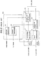
- the PCM terminal equipment 1a includes a multiplexer unit 2a, and channel units 3a1, 3a2, ..., 3an.
- the PCM terminal equipment 1b includes a multiplexer unit 2b, and channel units 3b1, 3b2, ..., 3bn.
- the channel units 3a1, 3a2, ..., 3an amounting to n channels, are coupled to a switch 5a through trunks 4a1, 4a2, ..., 4an, respectively.
- the trunks 4a1, 4a2, ..., 4an includes incoming trunks and outgoing trunks.
- the channel units 3b1, 3b2, ..., 3bn of the PCM terminal equipment 1b are coupled to a switch 5b through trunks 4b1, 4b2, ..., 4bn, respectively, which include incoming trunks and outgoing trunks.
- the switches 5a and 5b accommodate a number of subscribers through telephone lines.
- the channel units 3a1, 3a2, ..., 3an provided in the PCM terminal equipment 1a convert analog voice signals supplied from trunks 4a1, 4a2, ..., 4an to digital voice signals (PCM signals) to be supplied to the multiplexer unit 2a, and on the other hand, convert digital voice signals from the multiplexer unit 2a to analog voice signals to be supplied to the trunks 4a1, 4a2, ..., 4an.
- Each of the channel units 3a1, 3a2, ..., 3an also includes a signalling circuit, which processes switch signals such as a seizure signal and an answer signal.
- the multiplexer unit 2a of the PCM terminal equipment 1a carries out time-division multiplexing for the digital voice signals supplied from the channel units 3a1, 3a2, ..., 3an, and on the other hand, carried out time-division demultiplexing for multiplexed PCM signals supplied from the multiplexer unit 2b of the PCM terminal equipment 1b. Further, the multiplexer unit 2a has the function of multiplexing switch signals and the multiplexed PCM voice signal to be supplied to the PCM terminal equipment 1b, and the function of extracting (demultiplexing) switch signals from the multiplexed PCM signal sent from the PCM terminal equipment 1b.
- the channel units 3b1, 3b2, ..., 3bn provided in the PCM terminal equipment 1b operate in the same way as the channel units 3a1, 3a2, ..., 3an.
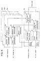
- the multiplexer unit 2a includes a voice multiplexer 7, a voice demultiplexer 8, a signalling multiplexer 9, and a signalling demultiplexer 10.
- the channel unit 3a1 includes a seizure supervisory circuit 12, and an answer supervisory circuit 13 in addition to a CODEC including an A/D converter and D/A converter (not shown in FIG.2).
- the voice multiplexer (MUX) 7 is a 30-voice channel multiplexer, which is constructed in conformity with CCITT recommendation G.732, for example.
- the multiplexer 7 of the PCM terminal equipment 1a generates a multiplexed PCM signal (voice signal) of a bit rate of 2.048 Mbps from the digital voice signals amounting to 30 channels supplied from the channel units 3a1, 3a2, ..., 3an.
- the multiplexed PCM signal is sent to the multiplexer unit 2b of the PCM terminal equipment 1b through the signalling multiplexer 9.
- the demultiplexer (DMUX) 8 of the PCM terminal equipment 1a generates demultiplexed digital voice signals amounting to 30 channels from a 2.048-Mbps multiplexed PCM signal supplied from the multiplexer 7 of the PCM terminal equipment 1b through the signalling demultiplexer 10.
- the signalling multiplexer 9 multiplexes a seizure signal derived from the seizure supervisory signal 12 into the multiplexed PCM signal relating to voice.
- the signalling demultiplexer 10 extracts switch signals from the multiplexed PCM signal supplied from the PCM terminal equipment 1b.
- the voice demultiplexer 8 has the function of detecting a fault occurring in the multiplexed PCM signal supplied from the PCM terminal equipment 1b. The detection of a fault depends on whether or not a hit occurs. When detecting a hit, the demultiplexer 8 outputs a fault detection signal, which is supplied to the seizure supervisory circuit 12 and the answer supervisory circuit 13.
- the seizure supervisory circuit 12 monitors whether or not a seizure signal is output from the trunk 4a1.
- a seizure signal is generated in response to a call signal generated by off-hook by a caller.
- the seizure supervisory circuit 12 sends the seizure signal received from the trunk 4a1 to the signalling multiplexer 9. Then, the seizure signal is inserted into the multiplexed PCM signal relating to voice supplied from the voice multiplexer 7.
- the answer supervisory circuit 13 monitors whether or not an answer signal is supplied from the signalling demultiplexer 10. When no fault occurs, the answer supervisory circuit 13 sends the received answer signal to the trunk 4a1.
- the seizure supervisory circuit 12 When a fault is detected in the seizure state, the seizure supervisory circuit 12 is supplied with both the seizure signal and the fault detection signal. At this time, the seizure supervisory circuit 12 stops passing the seizure signal supplied from the trunk 4a1. Thereby, the PCM terminal equipment 1b is informed of the intentional interruption of the seizure signal through the signalling multiplexer 9 and the PCM line. Then, the line is set idle. Thereafter the switch 5b blocks the related line in order to prevent the line from being captured by the switch 5b.
- the answer supervisory circuit 13 is supplied with both the answer signal and the fault detection signal. At this time, the answer supervisory circuit 13 stops passing the answer signal supplied from the signalling demodulator 10. Thereby, the trunk 4a1 becomes supplied with no answer signal. Thus, the line is set idle.
- the voice demultiplexer 8 recongizes a hit in the order of hundreds of milliseconds to a few seconds to be a fault. At this time, if the line is already in the seizure state, the line is set idle and disconnected from the connected state. Similarly, if the line is already in the answer state, the line is set idle and disconnected from the connected state. However, it is to be noted that there is a possibility that a hit in the order of hundreds of milliseconds to a few seconds may frequently occur. For example, if the quality of PCM lines is not good, the above-mentioned hit may frequently occur.
- FIG.3 A description is given of a preferred embodiment of the present invention with reference to FIG.3, in which those parts which are the same as those in FIG.2 are given the same reference numerals.
- the channel unit 3a1 includes a fault supervisory circuit 21, a seizure supervisory circuit 22, an answer supervisory circuit 23, and hold processing circuits 24 and 25.
- the fault supervisory circuit 21 monitors whether or not the fault detection signal is output from the voice demultiplexer 8. When receiving the fault detection signal, the fault supervisory circuit 21 passes the fault detection signal. It is noted that the fault detection signal derived from the voice demultiplexer 8 is supplied, through the fault supervisory circuit 21, to each of the channel units 3a1, 3a2, ..., 3an.
- the fault detection signal is supplied to the hold processing circuits 24 and 25, which are associated with the seizure supervisory circuit 22 and the answer supervisory circuit 23, respectively.
- the seizure supervisory circuit 22 receives the seizure signal supplied from the trunk 4a1, and supplies the received seizure signal to the hold processing circuit 24.
- the hold processing circuit 24 passes the seizure signal supplied from the seizure supervisory circuit 22, when no fault detection signal is supplied thereto.
- the hold processing circuit 24 operates as follows, when the fault detection signal is supplied thereto in the case where the seizure signal is being supplied thereto. In this case, the hold processing circuit 24 holds the seizure signal during a predetermined time. Therefore, during this time, the seizure signal is continuously supplied to the signalling multiplexer 9.
- the hold processing circuit 24 prevents the seizure signal from being supplied to the signalling multiplexer 9.
- the above-mentioned predetermined time is set equal to 2 to 3 seconds, for example. It depends on various conditions such as the line quality and requirements by users.
- the seizure signal is prevented from being supplied to the signalling multiplexer 9 at the time of the occurrence of the fault.
- the answer supervisory circuit 23 receives the related answer signal from the signalling demultiplexer 10, and supplies the hold processing circuit 25 with the received answer signal.
- the hold processing circuit 25 passes the answer signal from the 23, when no fault occurs. In the state where the answer signal is being supplied to the hold processing circuit 25, even if the fault signal is supplied thereto, the hold processing circuit 25 passes the answer signal. On the other hand, when the fault detection signal is supplied to the hold processing circuit 25 before the answer signal is supplied thereto, the hold processing circuit 25 prevents the answer signal from being supplied to the trunk 4a1.
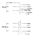
- FIG.4(A) shows a continuous fault.
- the fault detection signal of FIG.4(A) is supplied to the hold processing circuits 24 and 25 through the fault supervisory circuit 21.
- the seizure signal supplied to the seizure supervisory circuit 22 has already been turned ON when the fault detection signal is turned ON at time t 1 . Therefore, the hold processing circuit 24 continues to output the seizure signal during the predetermined time, 2 to 3 seconds, for example. Then, the hold processing circuit 24 prevents the seizure signal from being supplied to the signalling multiplexer 9.
- This change of the seizure signal is sent to the switch 5b (FIG.1) through the signalling multiplexer 9, the PCM line, and the PCM terminal equipment 1b. Thereby, the related line is set idle and disconnected from the line connection in a conventional way.
- FIG.5(A) shows the case where the answer signal has already been supplied to the answer supervisory circuit 23 when the fault signal shown in FIG.5(A) is turned ON at time t 1 .
- the answer signal is continuously supplied to the trunk 4a1 from the hold processing circuit 25 in the same way as in the case of the answer signal shown in FIG.4(B).
- FIG.5(C) the seizure signal has already been supplied to the seizure supervisory circuit 22 when the fault signal shown in FIG.5(A) is turned ON at time t 1 . Since the fault occurs during the time T shorter than the predetermined time, the hold processing circuit 24 continuously outputs the seizure signal.
- broken lines show corresponding signal changes in the conventional method.
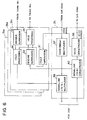
- FIG.6 illustrates an example of the structure for the multiplexer unit 2b and the channel unit 3b1 provided in the PCM terminal equipment 1b.
- the multiplexer unit 2b includes a voice multiplexer 37, a voice demultiplexer 38, and signalling circuits 39 and 40. Each of those circuits can operate in the same way as the corresponding circuit shown in FIG.3.
- the channel unit 3b1 includes a fault supervisory circuit 31, a seizure supervisory circuit 32, an answer supervisory circuit 33, and hold processing circuits 34 and 35, in the same way as the channel unit 3a1 shown in FIG.3. Each of those circuits 31 to 35 can operate in the same way as corresponding circuit shown in FIG.3.
- the seizure supervisory circuit 32 receives a seizure signal from the signalling demultiplexer 10, and sends it to the hold processing circuit 35.
- the seizure signal from the hold processing circuit 35 is supplied to the trunk 4b1 in the same way as in the case of FIG.3.
- An answer signal is supplied to the answer supervisory circuit 33 from the trunk 4b1.
- the channel unit 3b1 operates as shown in FIGS.4 and 5.
- the other channel units may be constructed in the same way as the above-mentioned channel unit 3b1.
- the fault supervisory circuit 21 includes a relay ALM having a couple of two-position switches 'alm'.
- the seizure supervisory circuit 22 includes a relay SEZ connected to a positive power source.
- the relay SEZ has three make contacts 'sez'.
- the hold process circuit 24 includes a timer TM having a break contact 'tm', a relay ALMB having two break contacts 'almb' and one of the make contacts 'sez', which is connected to ground.
- the answer supervisory circuit 23 includes a relay ANS connected to the positive power source, and one of the switches 'alm'.
- the relay ANS has two make contacts 'ans'.
- the hold processing circuit 25 includes one of the make contacts 'ans' connected to ground.
- break and make contacts are simply referred to as contacts.
- the seizure signal from the trunk 4a1 is changed to ground level, and applied to the relay SEZ through the contact 'alm'. It is now assumed that at this time, no fault is detected by the voice demultiplexer 8.
- the relay ALM is supplied with the fault detection signal held at the positive power source level (hereinafter simply referred to a positive level), and its contacts 'alm' are held closed.
- the relay SEZ is a relay having a timer circuit, and holds the previous state thereof during a fixed time after a fault occurs.
- the seizure signal is supplied to the signalling circuit 9, and is then sent to the PCM terminal equipment 1b and the switch 5b.
- the fault detection signal is supplied to the fault supervisory circuit 21 from the voice demultiplexer 8 after the seizure signal is turned ON. At this time, the fault detection signal is switched to ground level. Thereby, the relay ALM starts operating, and the contacts thereof are made open. Then, the fault detection signal fixed to ground level is supplied to the timer TM through the contacts 'sez' and 'almb'. Thereby, the timer TM starts operating.
- the timer TM is a timer which counts two seconds, which correspond to the aforementioned fixed time. The timer TM makes its contact 'tm' open when the fault detection signal is supplied thereto, and then makes the contact 'tm' closed after the lapse of two seconds.
- the relay ALMB does not operate until the timer TM is turned ON. Therefore, the relay SEZ is continuously supplied with ground level through the contacts 'almb', 'sez' and 'alm'. Thus, the seizure signal is continuously supplied to the signalling multiplexer 9.
- the answer signal When the answer signal is turned ON, it is switched to ground level.
- the answer signal When no fault is detected by the voice demultiplexer 8, the answer signal is supplied to the relay ANS through the contact 'alm'. Thereby the contact 'ans' of the relay ANS is made closed, and the answer signal is supplied to the trunk 4a1. Thereafter if the fault detection signal is turned ON, the relay ALM starts operating.
- the relay ANS includes a timer circuit, and therefore can maintain its previous state for a while after the relay ALM is turned ON. Therefore, even when the relay ANS is supplied with ground level through the contact 'ans', the relay ANS is continuously held ON. As a result, the trunk 4a1 is continuously supplied with the answer signal.
- the above-mentioned operation corresponds to the operation illustrated in FIGS.4(A), 4(B), 5(A) and 5(B).
- FIG.8 illustrates an example of the structure for the channel unit 3b1 provided in the PCM terminal equipment 1b.
- the channel unit 3b1 includes the same structural elements as the channel unit 3a1, and operates in the same way as the channel unit 3a1.
- the fault supervisory circuit 31 includes a relay ALM having a couple of two-position switches 'alm'.
- the seizure supervisory circuit 32 includes a relay SEZ connected to a positive power source.
- the relay SEZ has three make contacts 'sez'.
- the hold process circuit 34 includes a timer TM having a break contact 'tm', a relay ALMB having two break contacts 'almb' and one of the make contacts 'sez', which is connected to ground.
- the answer supervisory circuit 33 includes a relay ANS connected to the positive power source, and one of the switches 'alm'.
- the relay ANS has two make contacts 'ans'.
- the hold processing circuit 35 includes one of the make contacts 'ans' connected to ground
- the seizure signal from the signalling demultiplexer 40 is supplied to the relay SEZ through the contact 'alm', and is supplied to the trunk 4b1 through the contact 'sez'.
- the answer signal from the trunk 4b1 is supplied to the relay ANS through the contact 'alm', and to the signalling multiplexer 39 through the contact 'ans'.
- the PCM terminal equipment 1a includes the structure shown in FIGS.6 and 8, and on the other hand, the PCM terminal equipment 1b includes the structure shown in FIGS.3 and 7. In the alternative, it is possible to form the essential part of the channel units shown in FIGS.3, 6 to 8 by software.
- the predetermined time during which the seizure signal is maintained ON is not limited to 2 seconds.
- the predetermined time may be set equal to a time during which it is desired that said seizure signal is continuously supplied to said means even if said fault occurs.
Landscapes
- Engineering & Computer Science (AREA)
- Signal Processing (AREA)
- Computer Networks & Wireless Communication (AREA)
- Time-Division Multiplex Systems (AREA)
- Data Exchanges In Wide-Area Networks (AREA)
- Monitoring And Testing Of Exchanges (AREA)
Claims (28)
- Ein Pulscodemodulations-Endgerät (1a), das mit einer Vermittlungsstelle verbunden ist, die eine Vermittlungseinrichtung (5a) und Kanalbündel (4a1-4an) enthält, umfassend eine Multiplexereinrichtung (2a) zum(a) Multiplexen digitaler Signale und eines Belegungssignals, um dadurch ein erstes gemultiplextes digitales Signal auszugeben, um an ein weiteres Pulscodemodulations-Endgerät (1b) übertragen zu werden,(b) Demultiplexen eines zweiten gemultiplexten digitalen Signals, das von einem weiteren Pulscodemodulations-Endgerät (1b) zugeführt wird, um dadurch digitale Signale und ein Antwortsignal auszugeben, und(c) Erfassen eines Fehlers in dem zweiten gemultiplexten digitalen Signal, um dadurch ein Fehlererfassungssignal zu erzeugen,eine Fehleraufsichtseinrichtung (21), die mit der Multiplexereinrichtung (2a) verbunden ist, zum Erfassen ob das Fehlererfassungssignal von der Multiplexereinrichtung (2a) ausgegeben wird oder nicht, und Durchlassen des Fehlererfassungssignals wenn es erfaßt wird, eine Belegungsaufsichtseinrichtung (22), die mit einem der Kanalbündel (4a1) verbunden ist, zum Erfassen ob das Belegungssignal von dem einen entsprechenden Kanalbündel ausgegeben wird oder nicht, und Durchlassen des Belegungssignals, wenn es erfaßt wird, eine Antwortaufsichtseinrichtungen (23), die mit der Multiplexereinrichtung (2a) verbunden ist, zum Erfassen ob das Antwortsignal von der Multiplexereinrichtung (2a) ausgegeben wird oder nicht, und zum Durchlassen des Antwortsignals, wenn es erfaßt wird, eine erste Halteeinrichtung (24), die mit der Fehleraufsichtseinrichtung und der Belegungsaufsichtseinrichtung verbunden ist, zum Speichern des Belegungssignals, und eine zweite Halteeinrichtung (25), die mit der Fehleraufsichtseinrichtung (21) und der Antwortaufsichtseinrichtungen verbunden ist, zum Speichern des Antwortsignals,
dadurch gekennzeichnet, daß
die erste Halteeinrichtung (24) betreibbar ist, wenn das Belegungssignal zu dem gleichen Zeitpunkt empfangen wird wie das Fehlererfassungssignal, um die Multiplexereinrichtung (2a) kontinuierlich mit dem vorherigen Zustand des Belegungssignals zu versorgen, das von der Belegungsaufsichtseinrichtung (22) für eine vorbestimmte Zeit zugeführt wird, beginnend wenn die Fehleraufsichtseinrichtung (21) das Fehlererfassungssignal erfaßt, das von der Multiplexereinrichtung (2a) zugeführt wird, und um zu verhindern, daß das Belegungssignal der Multiplexereinrichtung (2a) nach dem Verstreichen der vorbestimmten Zeit zugeführt wird, und auch betreibbar ist, wenn das Fehlererfassungssignal vor dem Belegungssignal empfangen wird, um zu verhindern, daß das Belegungssignal der Multiplexereinrichtung (2a) zugeführt wird; und weiterhin
dadurch gekennzeichnet, daß
die zweite Halteeinrichtung (25) betreibbar ist, wenn das Antwortsignal zu dem gleichen Zeitpunkt, oder vor dem Fehlererfassungssignal empfangen wird, um kontinuierlich das entsprechende (4a1) der Kanalbündel mit dem vorherigen Zustand des Antwortsignals zu versorgen, das von der Antwortaufsichtseinrichtungen (23) zugeführt wird sogar nachdem die Fehleraufsichtseinrichtung (21) das Fehlererfassungssignal erfaßt, und ist auch betreibbar, wenn das Fehlererfassungssignal vor dem Antwortsignal empfangen wird, um zu verhindern, daß das Antwortsignal dem entsprechenden der Kanalbündel (4a1) zugeführt wird. - Ein Pulscodemodulations-Endgerät nach Anspruch 1,
dadurch gekennzeichnet, daß
das Pulscodemodulations-Endgerät eine Mehrzahl von Kanaleinheiten (3a1-3an) umfaßt, wobei jede für eines der Kanalbündel (4a1-4an) der Vermittlungsstelle vorgesehen ist, und jede der Kanaleinheiten die Fehleraufsichtseinrichtung (21), die Belegungsaufsichtseinrichtung (22), die Antwortaufsichtseinrichtungen (23), die erste Halteeinrichtung (24) und die zweite Halteeinrichtung (25) umfaßt. - Ein Pulscodemodulations-Endgerät nach einem der Ansprüche 1 oder 2,
dadurch gekennzeichnet, daß
die vorbestimmte Zeit einer Zeit gleichgesetzt wird, während der erwünscht wird, daß das Belegungssignal kontinuierlich der Multiplexereinrichtung (2a) zugeführt wird, sogar wenn der Fehler eintritt. - Ein Pulscodemodulations-Endgerät nach einem der Ansprüche 1 bis 3,
dadurch gekennzeichnet, daß
die Fehleraufsichtseinrichtung (21) ein erstes Relay (ALM) umfaßt, das EIN-geschaltet wird, wenn das Fehlererfassungssignal von der Multiplexereinrichtung (2a) bereitgestellt wird. - Ein Pulscodemodulations-Endgerät nach Anspruch 4,
dadurch gekennzeichnet, daß
das erste Relay (ALM) einen ersten Zwei-Positionsschalter (alm), mit ersten und zweiten Positionen hat, und daß die Belegungsaufsichtseinrichtung (22) ein zweites Relay (SEZ) umfaßt, an das das Belegungssignal von einem der Kanalbündel über die erste Position des ersten Zwei-Positionsschalters des ersten Relays zugeführt wird, wenn das erste Relay AUS ist. - Ein Pulscodemodulations-Endgerät nach Anspruch 5,
dadurch gekennzeichnet, daß
die erste Halteeinrichtung (24) erste Einrichtungen (TM, ALMB) umfaßt, um kontinuierlich das zweite Relay (SEZ) mit einem Haltesignal zu versorgen, das zum Halten des zweiten Relays auf EIN verwendet wird, während der vorbestimmten Zeit. - Ein Pulscodemodulations-Endgerät nach Anspruch 6,
dadurch gekennzeichnet, daß
die erste Einrichtung einen Zeitgeber (TM), der die vorbestimmte Zeit zählt, und ein drittes Relay (ALMB) umfaßt, das nach der vorbestimmten Zeit, die durch den Zeitgeber definiert wird, EIN-geschaltet wird, daß das zweite Relay (SEZ) einen ersten Schließkontakt (sez), und das dritte Relay (ALMB) einen ersten Unterbrecherkontakt (almb) hat, und daß das Haltesignal auf einen festen Pegel (Erdungspegel) eingestellt wird und dem zweiten Relay (SEZ) zugeführt wird, das durch den ersten Unterbrecherkontakt des dritten Relays, den ersten Schließkontakt des zweiten Relays, und die zweite Position des ersten Zwei-Positionsschalters (almb) des ersten Relays (ALM) hindurchtritt. - Ein Pulscodemodulations-Endgerät nach einem der Ansprüche 5 bis 7,
dadurch gekennzeichnet, daß
das zweite Relay (SEZ) der ersten Halteeinrichtung (24) einen zweiten Kontakt (sez) umfaßt, das die Einrichtung (2a) mit dem festen Pegel versorgt, wenn das zweite Relay EIN ist. - Ein Pulscodemodulations-Endgerät nach Anspruch 7, oder Anspruch 7 und 8,
dadurch gekennzeichnet, daß
der Zeitgeber (TM) einen Unterbrecherkontakt (tm), und das dritte Relay (ALMB) einen zweiten Unterbrecherkontakt (almb) hat, und daß das Fehlererfassungssignal dem Zeitgeber über den zweiten Unterbrecherkontakt des ersten Relays zugeführt wird, und dem dritten Relay über den Unterbrecherkontakt des Zeitgebers zugeführt wird. - Ein Pulscodemodulations-Endgerät nach Anspruch 9,
dadurch gekennzeichnet, daß
das zweite Relay (SEZ) einen dritten Schließkontakt (sez) hat, und daß das erste Fehlererfassungssignal durch den dritten Schließkontakt des zweiten Relays und durch den zweiten Unterbrecherkontakt (almb) des dritten Relays (ALMB) hindurchtritt, und dem Zeitgeber (TM) zugeführt wird, wodurch der Zeitgeber EIN-geschaltet wird, wenn das Fehlererfassungssignal von der Vorrichtung (2a) ausgegeben wird. - Ein Pulscodemodulations-Endgerät nach einem der Ansprüche 5 bis 10,
dadurch gekennzeichnet, daß
das erste Relay (ALM) einen zweiten Zwei-Positionsschalter (alm) mit ersten und zweiten Positionen hat, und daß die Antwortaufsichtseinrichtungen (23) ein viertes Relay (ANS) umfaßt, an das das Antwortsignal über die erste Position des zweiten Zwei-Positionsschalters bereitgestellt wird. - Ein Pulscodemodulations-Endgerät nach Anspruch 11,
dadurch gekennzeichnet, daß
das vierte Relay einen ersten Schließkontakt hat, und daß die zweite Halteeinrichtung den ersten Schließkontakt des vierten Relays umfaßt, durch den ein fester Pegel als Antwortsignal an das entsprechende (4a1) der Kanalbündel bereitgestellt wird. - Ein Pulscodemodulations-Endgerät nach Anspruch 12,
dadurch gekennzeichnet, daß
das vierte Relay (ANS) einen zweiten Schließkontakt (ans) hat, durch den der feste Pegel an die zweite Position des zweiten Zwei-Positionsschalters des ersten Relays (ALM) bereitgestellt wird. - Ein Pulscodemodulations-Endgerät nach einem der Ansprüche 1 bis 13,
dadurch gekennzeichnet, daß
jedes der ersten und zweiten gemultiplexten digitalen Signale ein gemultiplextes Pulscodemodulations-Signal ist. - Ein Pulscodemodulations-Endgerät (1b), das mit einer Vermittlungsstelle verbunden ist, die eine Vermittlungseinrichtung (5b) und Kanalbündel (4b1-4bn) enthält, umfassend eine Multiplexereinrichtung (2b) zum(a) Multiplexen digitaler Signale und eines Antwortsignals, um dadurch ein erstes gemultiplextes digitales Signal zu erzeugen, um an ein weiteres Pulscodemodulations-Endgerät (la) übertragen zu werden,(b) Demultiplexen eines zweiten gemultiplexten digitalen Signals, das von einem weiteren Pulscodemodulations-Endgerät (la) zugeführt wird, um dadurch digitale Signale und ein Belegungssignal auszugeben, und(c) Erfassen eines Fehlers in dem zweiten gemultiplexten digitalen Signal, um dadurch ein Fehlererfassungssignal zu erzeugen,eine Fehleraufsichtseinrichtung (31), die mit der Multiplexereinrichtung verbunden ist, zum Erfassen ob das Fehlererfassungssignal von der Multiplexereinrichtung ausgegeben wird oder nicht, und Durchlassen des Fehlererfassungssignals, wenn es erfaßt wird, eine Belegungsaufsichtseinrichtung (32), die mit der Multiplexereinrichtung verbunden ist, zum Erfassen ob das Belegungssignal von der Multiplexereinrichtung erfaßt wird oder nicht, und Durchlassen des Belegungssignals, wenn es erfaßt wird, eine Antwortaufsichtseinrichtungen (33), die mit einem entsprechenden der Kanalbündel (4b1) verbunden ist, zum Erfassen ob das Antwortsignal von dem entsprechenden der Kanalbündel (4b1) erfaßt wird oder nicht, und Durchlassen des Antwortsignal, wenn es erfaßt wird, eine erste Halteeinrichtung (34), die mit der Fehleraufsichtseinrichtung und der Belegungsaufsichtseinrichtung verbunden ist, zum Speichern des Belegungssignals, und eine zweite Halteeinrichtung (35), die mit der Fehleraufsichtseinrichtung (31) und der Antwortaufsichtseinrichtungen (33) verbunden ist, zum Speichern des Antwortsignals, und
dadurch gekennzeichnet, daß
die erste Halteeinrichtung (34) betreibbar ist, wenn das Belegungssignal zu dem gleichen Zeitpunkt empfangen wird wie das Fehlererfassungssignal, um kontinuierlich das entsprechende der Kanalbündel (4b1) mit dem vorherigen Zustand des Belegungssignals zu Versorgen, das von der Belegungsaufsichtseinrichtung (32) für eine vorbestimmte Zeit zugeführt wird, beginnend wenn die Fehleraufsichtseinrichtung (31) das Fehlererfassungssignal erfaßt, das von der Multiplexereinrichtung (2b) zugeführt wird, und um zu verhindern, daß das Belegungssignal dem entsprechenden Kanalbündel (4b1) nach dem Verstreichen der vorbestimmten Zeit zugeführt wird, und auch betreibbar ist, wenn das Fehlererfassungssignal vor dem Belegungssignal empfangen wird, um zu verhindern, daß das Belegungssignal dem entsprechenden Kanalbündel (4b1) zugeführt wird, und ist weiterhin
dadurch gekennzeichnet, daß
die zweite Halteeinrichtung (35) betreibbar ist, wenn das Antwortsignal zu dem gleichen Zeitpunkt, oder vor dem Fehlererfassungssignal empfangen wird, um die Multiplexereinrichtung (2b) kontinuierlich mit dem vorherigen Zustand des Antwortsignals zu versorgen, das von der Antwortaufsichtseinrichtung (33) zugeführt wird sogar nachdem die Fehleraufsichtseinrichtung (31) das Fehlererfassungssignal erfaßt, und ist auch betreibbar, wenn das Fehlererfassungssignal vor dem Antwortsignal empfangen wird, um zu verhindern, daß das Antwortsignal der Multiplexereinrichtung (2b) zugeführt wird. - Ein Pulscodemodulations-Endgerät nach Anspruch 15,
dadurch gekennzeichnet, daß das Pulscodemodulations-Endgerät eine Mehrzahl von Kanaleinheiten (3b1-3bn) umfaßt, wobei jede für eines der Kanalbündel (4b1-4bn) der Vermittlungsstelle vorgesehen ist, und jede der Kanaleinheiten die Fehleraufsichtseinrichtung (31), die Belegungsaufsichtseinrichtung (32), die Antwortaufsichtseinrichtungen (33), die erste Halteeinrichtung (34) und die zweite Halteeinrichtung (35) umfaßt. - Ein Pulscodemodulations-Endgerät nach einem der Ansprüche 15 und 16,
dadurch gekennzeichnet, daß
die vorbestimmte Zeit gleich einer Zeit gesetzt wird, während der erwünscht wird, daß das Belegungssignal kontinuierlich dem entsprechenden Kanalbündel (4b1) zugeführt wird, sogar wenn der Fehler eintritt. - Ein Pulscodemodulations-Endgerät nach einem der Ansprüche 15 bis 17,
dadurch gekennzeichnet, daß
die Fehleraufsichtseinrichtung (31) ein erstes Relay (ALM) umfaßt, das EIN-geschaltet wird, wenn das Fehlererfassungssignal von der Multiplexereinrichtung (2b) bereitgestellt wird. - Ein Pulscodemodulations-Endgerät nach Anspruch 18,
dadurch gekennzeichnet, daß
das erste Relay (ALM) einen ersten Zwei-Positionsschalter (ALM) mit ersten und zweiten Positionen hat, und daß die Belegungsaufsichtseinrichtung (32) ein zweites Relay (SEZ) umfaßt, an daß das Belegungssignal von der Einrichtung (2b) über die erste Position des ersten Zwei-Positionsschalters des ersten Relays zugeführt wird, wenn das erste Relay AUS ist. - Ein Pulscodemodulations-Endgerät nach Anspruch 19,
dadurch gekennzeichnet, daß
die erste Halteeinrichtung (34) erste Einrichtungen (TM, ALMB) umfaßt, um kontinuierlich das zweite Relay mit einem Haltesignal zu versorgen, das zum Halten des zweiten Relays auf EIN verwendet wird, während der vorbestimmten Zeit. - Ein Pulscodemodulations-Endgerät nach Anspruch 20,
dadurch gekennzeichnet, daß
die erste Einrichtung einen Zeitgeber (TM), der die vorbestimmte Zeit zählt, und ein drittes Relay (ALMB) umfaßt, das nach der vorbestimmten Zeit, die durch den Zeitgeber definiert wird, EIN-geschaltet wird, daß das zweite Relay (SEZ) einen ersten Schließkontakt (sez) und das dritte Relay (ALMB) einen ersten Unterbrecherkontakt (almb) hat, und daß das Haltesignal auf einen festen Pegel (Erdungspegel) eingestellt wird, und dem zweiten Relay (SEZ) über den ersten Unterbrecherkontakt (almb) des dritten Relays (ALMB), dem ersten Schließkontakt (sez) des zweiten Relays (SEZ) und der zweiten Position des ersten Zwei-Positionsschalters (alm) des ersten Relays (ALM) zugeführt wird. - Ein Pulscodemodulations-Endgerät nach einem der Ansprüche 19 bis 21,
dadurch gekennzeichnet, daß
das zweite Relay (SEZ) der ersten Halteeinrichtung (34) einen zweiten Kontakt (sez) umfaßt, der das entsprechende Kanalbündel (4b1) mit dem festen Pegel versorgt, wenn das zweite Relay EIN ist. - Ein Pulscodemodulations-Endgerät nach Anspruch 21, oder nach Anspruch 21 und 22,
dadurch gekennzeichnet, daß
der Zeitgeber (TM) einen Unterbrecherkontakt (tm) hat, und das dritte Relay (ALMB) einen zweiten Unterbrecherkontakt (almb) hat, und daß das Fehlererfassungssignal dem Zeitgeber über den zweiten Unterbrecherkontakt des dritten Relays zugeführt wird, und dem dritten Relay über den Unterbrecherkontakt des Zeitgebers zugeführt wird. - Ein Pulscodemodulations-Endgerät nach Anspruch 23,
dadurch gekennzeichnet, daß
das zweite Relay (SEZ) einen dritten Schließkontakt (sez) hat, und daß das Fehlererfassungssignal durch den dritten Schließkontakt (sez) des zweiten Relays (SEZ), und durch den zweiten Unterbrecherkontakt (almb) des dritten Relays (ALMB) hindurchtritt, und dem Zeitgeber (TM) zugeführt wird, wodurch der Zeitgeber EIN-geschaltet wird, wenn das Fehlererfassungssignal von der Multiplexereinrichtung bereitgestellt wird. - Ein Pulscodemodulations-Endgerät nach einem der Ansprüche 19 - 24,
dadurch gekennzeichnet, daß
das erste Relay (ALM) einen zweiten Zwei-Positionsschalter (alm) mit ersten und zweiten Positionen hat, und daß die Antwortaufsichtseinrichtung (33) ein viertes Relay (ANS) umfaßt, an das das Antwortsignal über die erste Position des zweiten Zwei-Positionsschalters (alm) bereitgestellt wird. - Ein Pulscodemodulations-Endgerät nach Anspruch 25,
dadurch gekennzeichnet, daß
das vierte Relay (ANS) einen ersten Schließkontakt (ans) hat, und daß die zweite Halteeinrichtung (35) den ersten Schließkontakt des vierten Relays umfaßt, durch den ein fester Pegel als Antwortsignal der Multiplexereinrichtung (2b) zugeführt wird. - Ein Pulscodemodulations-Endgerät nach Anspruch 26,
dadurch gekennzeichnet, daß
das vierte Relay (ANS) einen zweiten Schließkontakt (ans) hat, durch den der feste Pegel der zweiten Position des Zwei-Positionsschalters (alm) des ersten Relays (ALM) zugeführt wird. - Ein Pulscodemodulations-Endgerät nach Anspruch 15,
dadurch gekennzeichnet, daß
jedes der ersten und zweiten gemultiplexten digitalen Signale ein gemultiplextes Pulscodemodulationssignal ist.
Applications Claiming Priority (2)
| Application Number | Priority Date | Filing Date | Title |
|---|---|---|---|
| JP63119484A JPH01289333A (ja) | 1988-05-17 | 1988-05-17 | 障害時の呼処理方式 |
| JP119484/88 | 1988-05-17 |
Publications (3)
| Publication Number | Publication Date |
|---|---|
| EP0342593A2 EP0342593A2 (de) | 1989-11-23 |
| EP0342593A3 EP0342593A3 (de) | 1990-11-22 |
| EP0342593B1 true EP0342593B1 (de) | 1997-12-10 |
Family
ID=14762422
Family Applications (1)
| Application Number | Title | Priority Date | Filing Date |
|---|---|---|---|
| EP89108758A Expired - Lifetime EP0342593B1 (de) | 1988-05-17 | 1989-05-16 | Pulskodenmoduliertes Endstellengerät |
Country Status (5)
| Country | Link |
|---|---|
| US (1) | US4912699A (de) |
| EP (1) | EP0342593B1 (de) |
| JP (1) | JPH01289333A (de) |
| CA (1) | CA1320553C (de) |
| DE (1) | DE68928479T2 (de) |
Family Cites Families (8)
| Publication number | Priority date | Publication date | Assignee | Title |
|---|---|---|---|---|
| US3715503A (en) * | 1971-02-16 | 1973-02-06 | Stromberg Carlson Corp | Automatic transfer arrangement for telephone system |
| US3851311A (en) * | 1973-09-17 | 1974-11-26 | Gte Automatic Electric Lab Inc | Arrangement and method for protecting a common highway from false signals |
| JPS5854704B2 (ja) * | 1978-08-11 | 1983-12-06 | 富士通株式会社 | 電子交換機のネツトワ−ク疑似障害検知方式 |
| JPS5842261A (ja) * | 1981-09-07 | 1983-03-11 | Mitsubishi Electric Corp | 機能回路の放熱方法 |
| JPS58109442A (ja) * | 1981-12-22 | 1983-06-29 | Toa Nenryo Kogyo Kk | カルボニル化合物の製造方法 |
| US4558317A (en) * | 1982-11-17 | 1985-12-10 | Paradyne Corporation | Digital communication link monitoring device |
| JPS60214147A (ja) * | 1984-04-09 | 1985-10-26 | Fujitsu Ltd | E線への信号送出装置 |
| US4920921A (en) * | 1988-04-01 | 1990-05-01 | Ochs Gordon M | Modular aquaculture fish pen assembly with slidable divider |
-
1988
- 1988-05-17 JP JP63119484A patent/JPH01289333A/ja active Pending
-
1989
- 1989-05-16 US US07/352,403 patent/US4912699A/en not_active Expired - Lifetime
- 1989-05-16 EP EP89108758A patent/EP0342593B1/de not_active Expired - Lifetime
- 1989-05-16 CA CA000599841A patent/CA1320553C/en not_active Expired - Fee Related
- 1989-05-16 DE DE68928479T patent/DE68928479T2/de not_active Expired - Fee Related
Non-Patent Citations (1)
| Title |
|---|
| 60 214186 * |
Also Published As
| Publication number | Publication date |
|---|---|
| DE68928479D1 (de) | 1998-01-22 |
| US4912699A (en) | 1990-03-27 |
| EP0342593A3 (de) | 1990-11-22 |
| CA1320553C (en) | 1993-07-20 |
| JPH01289333A (ja) | 1989-11-21 |
| DE68928479T2 (de) | 1998-04-30 |
| EP0342593A2 (de) | 1989-11-23 |
Similar Documents
| Publication | Publication Date | Title |
|---|---|---|
| US5418776A (en) | Emergency local switching | |
| CA1274009A (en) | Tdma communication system having common local path medium and local time slot for intraoffice calls | |
| US4922484A (en) | ISDN remote switching unit for accommodating analog and digital lines | |
| NZ196421A (en) | Terminal units for subscriber and exchange line circuits in digital t.d.m.telephony system:main and subchannel formed on line | |
| JPH0795325A (ja) | 光加入者伝送システムに於ける給電制御方式 | |
| EP0809919B1 (de) | Verfahren und anordnung zur herstellung von informationen über trägerkapazität | |
| CA1184638A (en) | Arrangement for multiple custom calling | |
| EP0342593B1 (de) | Pulskodenmoduliertes Endstellengerät | |
| US5548584A (en) | Telephone switching system with switched line circuits | |
| US5303239A (en) | Telephone system | |
| US6404887B1 (en) | Intra-call control of ancillary telecommunications equipment | |
| NZ196422A (en) | Subscriber terminal equipment power turn on in digital communication system | |
| CA1184639A (en) | Arrangement for multiple custom calling | |
| US5157715A (en) | Call status recognition in a broadband private automatic branch exchange | |
| EP0331531B1 (de) | Telefonapparat und Steuerungsverfahren dafür | |
| US4445212A (en) | Arrangement for multiple custom calling | |
| JPH05110582A (ja) | 音声呼の無切断通信方法 | |
| JPH02226948A (ja) | 発信者限定音声多重化方式 | |
| JPH03135148A (ja) | 同時通信発信接続制御方式 | |
| JPH02295329A (ja) | 加入者収容交換装置 | |
| JPH10108227A (ja) | 構内交換機と無線サービス提供装置との相互接続装置 | |
| JPH06165273A (ja) | 過負荷制御pcm端局装置 | |
| JPS6369399A (ja) | デイジタル交換方式 | |
| JPS6374248A (ja) | 周波数分割多重回線を収容する電話交換装置 | |
| JPH08237375A (ja) | 専用回線通信の故障救済方式 |
Legal Events
| Date | Code | Title | Description |
|---|---|---|---|
| PUAI | Public reference made under article 153(3) epc to a published international application that has entered the european phase |
Free format text: ORIGINAL CODE: 0009012 |
|
| AK | Designated contracting states |
Kind code of ref document: A2 Designated state(s): DE FR GB SE |
|
| PUAL | Search report despatched |
Free format text: ORIGINAL CODE: 0009013 |
|
| AK | Designated contracting states |
Kind code of ref document: A3 Designated state(s): DE FR GB SE |
|
| RHK1 | Main classification (correction) |
Ipc: H04B 1/74 |
|
| 17P | Request for examination filed |
Effective date: 19901221 |
|
| 17Q | First examination report despatched |
Effective date: 19930108 |
|
| GRAG | Despatch of communication of intention to grant |
Free format text: ORIGINAL CODE: EPIDOS AGRA |
|
| GRAG | Despatch of communication of intention to grant |
Free format text: ORIGINAL CODE: EPIDOS AGRA |
|
| GRAH | Despatch of communication of intention to grant a patent |
Free format text: ORIGINAL CODE: EPIDOS IGRA |
|
| RBV | Designated contracting states (corrected) |
Designated state(s): DE FR GB |
|
| GRAH | Despatch of communication of intention to grant a patent |
Free format text: ORIGINAL CODE: EPIDOS IGRA |
|
| GRAA | (expected) grant |
Free format text: ORIGINAL CODE: 0009210 |
|
| AK | Designated contracting states |
Kind code of ref document: B1 Designated state(s): DE FR GB |
|
| REF | Corresponds to: |
Ref document number: 68928479 Country of ref document: DE Date of ref document: 19980122 |
|
| ET | Fr: translation filed | ||
| PLBE | No opposition filed within time limit |
Free format text: ORIGINAL CODE: 0009261 |
|
| STAA | Information on the status of an ep patent application or granted ep patent |
Free format text: STATUS: NO OPPOSITION FILED WITHIN TIME LIMIT |
|
| 26N | No opposition filed | ||
| REG | Reference to a national code |
Ref country code: GB Ref legal event code: IF02 |
|
| PGFP | Annual fee paid to national office [announced via postgrant information from national office to epo] |
Ref country code: FR Payment date: 20040510 Year of fee payment: 16 |
|
| PGFP | Annual fee paid to national office [announced via postgrant information from national office to epo] |
Ref country code: GB Payment date: 20040512 Year of fee payment: 16 |
|
| PGFP | Annual fee paid to national office [announced via postgrant information from national office to epo] |
Ref country code: DE Payment date: 20040527 Year of fee payment: 16 |
|
| PG25 | Lapsed in a contracting state [announced via postgrant information from national office to epo] |
Ref country code: GB Free format text: LAPSE BECAUSE OF NON-PAYMENT OF DUE FEES Effective date: 20050516 |
|
| PG25 | Lapsed in a contracting state [announced via postgrant information from national office to epo] |
Ref country code: DE Free format text: LAPSE BECAUSE OF NON-PAYMENT OF DUE FEES Effective date: 20051201 |
|
| GBPC | Gb: european patent ceased through non-payment of renewal fee |
Effective date: 20050516 |
|
| PG25 | Lapsed in a contracting state [announced via postgrant information from national office to epo] |
Ref country code: FR Free format text: LAPSE BECAUSE OF NON-PAYMENT OF DUE FEES Effective date: 20060131 |
|
| REG | Reference to a national code |
Ref country code: FR Ref legal event code: ST Effective date: 20060131 |