EP0342593A2 - Pulskodenmoduliertes Endstellengerät - Google Patents
Pulskodenmoduliertes Endstellengerät Download PDFInfo
- Publication number
- EP0342593A2 EP0342593A2 EP89108758A EP89108758A EP0342593A2 EP 0342593 A2 EP0342593 A2 EP 0342593A2 EP 89108758 A EP89108758 A EP 89108758A EP 89108758 A EP89108758 A EP 89108758A EP 0342593 A2 EP0342593 A2 EP 0342593A2
- Authority
- EP
- European Patent Office
- Prior art keywords
- relay
- signal
- terminal equipment
- supplied
- pulse code
- Prior art date
- Legal status (The legal status is an assumption and is not a legal conclusion. Google has not performed a legal analysis and makes no representation as to the accuracy of the status listed.)
- Granted
Links
Images


Classifications
-
- H—ELECTRICITY
- H04—ELECTRIC COMMUNICATION TECHNIQUE
- H04M—TELEPHONIC COMMUNICATION
- H04M3/00—Automatic or semi-automatic exchanges
- H04M3/22—Arrangements for supervision, monitoring or testing
- H04M3/24—Arrangements for supervision, monitoring or testing with provision for checking the normal operation
- H04M3/244—Arrangements for supervision, monitoring or testing with provision for checking the normal operation for multiplex systems
-
- H—ELECTRICITY
- H04—ELECTRIC COMMUNICATION TECHNIQUE
- H04J—MULTIPLEX COMMUNICATION
- H04J3/00—Time-division multiplex systems
- H04J3/02—Details
- H04J3/14—Monitoring arrangements
Definitions
- the present invention generally relates to a pulse code modulation terminal equipment, and in particular to a call processing which is to be executed in a pulse code modulation terminal equipment when a fault occurs in a pulse code modulation communication system.
- a pulse code modulation (hereinafter simply referred to as a PCM) terminal equipment is used as a relay connected to an exchange in a communication system.
- a PCM terminal equipment includes signal conversion panels (hereinafter referred to channel units), which includes an analog-to-digital (A/D) converter, a digital-to-analog (D/A) converter, and a signalling circuit.
- the signalling circuit processes various supervisory signals such as a seizure signal and an answer signal.
- the PCM terminal equipment includes a multiplexer unit, which carries out time-division multiplexing and demultiplexing for voice signals and switch signals.
- a PCM terminal equipment is constructed so as to conform to the CCITT (International Telephone Consultative Committe) recommendation G.732, which defines a 30-channel pulse code modulation system.
- the multiplexer unit has the function of detecting a fault occurring in a multiplexed PCM signal supplied from another PCM terminal equipment. For example, when the multiplexer unit receives no multiplexed PCM signal from the PCM terminal equipment on the other side, it decides that a fault occurs in the system. Then, the signalling circuit in the source PCM terminal equipment sets a related line idle. Thereafter, the line in the idle state is blocked, and thereby prevented from being captured by an exchange.
- the multiplexer unit recognizes an interruption or hit of the received multiplexed PCM signal to be a fault thereof. It is to be noted that even when the multiplexed PCM signal is instantaneously interrupted, for example, for hundreds of milliseconds to a few seconds, this instantaneous interruption is recognized to be a fault, and the corresponding line is immediately set idle. In this case, if the related line is in an answer state, conversation is no longer continued. In the case where the line is set in the answer state, it is desired to keep the line in the connected state even when a hit occurs. Similarly, even if a hit occurs in a seizure state (off-hook state), the line is set idle.
- a more specific object of the present invention is to provide a pulse code modulation terminal equipment capable of utilizing lines efficiently and effectively.
- a pulse code modulation terminal equipment connected to an exchange including a switch and trunks, including a multiplexer unit for multiplexing digital signals and a seizure signal to generate a first multiplexed digital signal to be transmitted to another pulse code modulation terminal equipment, demultiplexing a second multiplexed digital signal supplied from another pulse code modulation terminal equipment to thereby generate digital signals and an answer signal, and detecting a fault in the second multiplexed digital signal to thereby generate a fault detection signal.
- a fault supervisory circuit which is connected to the multiplexer unit, detects whether or not the fault detection signal is output from the multiplexer unit and passes the fault detection signal when it is detected.
- a seizure supervisory circuit which connected to one of the trunks, for detecting whether or not the seizure signal is output from the one trunk and passing the seizure signal when it is detected.
- An answer supervisory circuit which is connected to the multiplexer unit, detects whether or not the answer signal is output from the multiplexer unit and passes the answer signal when it is detected.
- a first hold processing circuit which is connected to the fault supervisory circuit and the seizure supervisory circuit, continuously supplies the multiplexer unit with the seizure signal supplied from the seizure supervisory circuit during a predetermined time after the fault supervisory circuit detects the fault detection signal supplied from the multiplexer unit, and prevents the seizure signal from being supplied to the multiplexer unit after the lapse of the predetermined time.
- a second hold processing circuit which is connected to the fault supervisory circuit and the answer supervisory circuit, continuously supplies the related one of the trunks with the answer signal supplied from the answer supervisory circuit even after the fault supervisory circuit detects the fault detection signal.
- a pulse code modulation terminal equipment connected to an exchange including a switch and trunks, including a multiplexer unit for multiplexing digital signals and an answer signal to generate a first multiplexed digital signal to be transmitted to another pulse code modulation terminal equipment, demultiplexing a second multiplexed digital signal supplied from another pulse code modulation terminal equipment to thereby generate digital signals and a seizure signal, and detecting a fault in the second multiplexed digital signal to thereby generate a fault detection signal.
- a fault supervisory circuit which is connected to the multiplexer unit, detects whether or not the fault detection signal is output from the multiplexer unit and passes the fault detection signal when it is detected.
- a seizure supervisory circuit which is connected to the multiplexer unit, detects whether or not the seizure signal is output from the multiplexer unit and passes the seizure signal when it is detected.
- An answer answer supervisory circuit which is connected to related one of the trunks, detects whether or not the answer signal is output from the related one trunk and passes the answer signal when it is detected.
- a first hold processing circuit which is connected to the fault supervisory circuit and the seizure supervisory circuit, continuously supplies the related one trunk with the seizure signal supplied from the seizure supervisory circuit during a predetermined time after the fault supervisory circuit detects the fault detection signal supplied from the multiplexer unit, and prevents the seizure signal from being supplied to the related one trunk after the lapse of the predetermined time.
- a second hold processing circuit which is connected to the fault supervisory circuit and the answer supervisory circuit, continuously supplies the multiplexer unit with the answer signal supplied from the answer supervisory circuit even after the fault supervisory circuit detects the fault detection signal.
- the PCM terminal equipment 1a includes a multiplexer unit 2a, and channel units 3a1, 3a2, ..., 3an.
- the PCM terminal equipment 1b includes a multiplexer unit 2b, and channel units 3b1, 3b2, ..., 3bn.
- the channel units 3a1, 3a2, ..., 3an amounting to n channels, are coupled to a switch 5a through trunks 4a1, 4a2, ..., 4an, respectively.
- the trunks 4a1, 4a2, ..., 4an includes incoming trunks and outgoing trunks.
- the channel units 3b1, 3b2, ..., 3bn of the PCM terminal equipment 1b are coupled to a switch 5b through trunks 4b1, 4b2, ..., 4bn, respectively, which include incoming trunks and outgoing trunks.
- the switches 5a and 5b accommodate a number of subscribers through telephone lines.
- the channel units 3a1, 3a2, ..., 3an provided in the PCM terminal equipment 1a convert analog voice signals supplied from trunks 4a1, 4a2, ..., 4an to digital voice signals (PCM signals) to be supplied to the multiplexer unit 2a, and on the other hand, convert digital voice signals from the multiplexer unit 2a to analog voice signals to be supplied to the trunks 4a1, 4a2, ..., 4an.
- Each of the channel units 3a1, 3a2, ..., 3an also includes a signalling circuit, which processes switch signals such as a seizure signal and an answer signal.
- the multiplexer unit 2a of the PCM terminal equipment 1a carries out time-division multiplexing for the digital voice signals supplied from the channel units 3a1, 3a2, ..., 3an, and on the other hand, carried out time-division demultiplexing for multiplexed PCM signals supplied from the multiplexer unit 2b of the PCM terminal equipment 1b. Further, the multiplexer unit 2a has the function of multiplexing switch signals and the multiplexed PCM voice signal to be supplied to the PCM terminal equipment, and the function of extracting (demultiplexing) switch signals from the multiplexed PCM signal sent from the PCM terminal equipment 1b.
- the channel units 3b1, 3b2, ..., 3bn provided in the PCM terminal equipment 1b operate in the same way as the channel units 3a1, 3a2, ..., 3an.
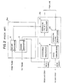
- the multiplexer unit 2a includes a voice multiplexer 7, a voice demultiplexer 8, a signalling multiplexer 9, and a signalling demultiplexer 10.
- the channel unit 3a1 includes a seizure supervisory circuit 12, and an answer supervisory circuit 13 in addition to a CODEC including an A/D converter and D/A converter (not shown in FIG.2).
- the voice multiplexer (MUX) 7 is a 30-voice channel multiplexer, which is constructed in conformity with CCITT recommendation G.732, for example.
- the multiplexer 7 of the PCM terminal equipment 1a generates a multiplexed PCM signal (voice signal) of a bit rate of 2.048 Mbps from the digital voice signals amounting to 30 channels supplied from the channel units 3a1, 3a2, ..., 3an.
- the multiplexed PCM signal is sent to the multiplexer unit 2b of the PCM terminal equipment 1b through the signalling multiplexer 9.
- the demultiplexer (DMUX) 8 of the PCM terminal equipment 1a generates demultiplexed digital voice signals amounting to 30 channels from a 2.048-Mbps multiplexed PCM signal supplied from the multiplexer 7 of the PCM terminal equipment 1b through the signalling demultiplexer 10.
- the signalling multiplexer 9 multiplexes a seizure signal derived from the seizure supervisory signal 12 into the multiplexed PCM signal relating to voice.
- the signalling demultiplexer 10 extracts switch signals from the multiplexed PCM signal supplied from the PCM terminal equipment 1b.
- the voice demultiplexer 8 has the function of detecting a fault occurring in the multiplexed PCM signal supplied from the PCM terminal equipment 1b. The detection of a fault depends on whether or not a hit occurs. When detecting a hit, the demultiplexer 8 outputs a fault detection signal, which is supplied to the seizure supervisory circuit 12 and the answer supervisory circuit 13.
- the seizure supervisory circuit 12 monitors whether or not a seizure signal is output from the trunk 4a1.
- a seizure signal is generated in response to a call signal generated by off-hook by a caller.
- the seizure supervisory circuit 12 sends the seizure signal received from the trunk 4a1 to the signalling multiplexer 9. Then, the seizure signal is inserted into the multiplexed PCM signal relating to voice supplied from the voice multiplexer 7.
- the answer supervisory circuit 13 monitors whether or not an answer signal is supplied from the signalling demultiplexer 10. When no fault occurs, the answer supervisory circuit 13 sends the received answer signal to the trunk 4a1.
- the seizure supervisory circuit 12 When a fault is detected in the seizure state, the seizure supervisory circuit 12 is supplied with both the seizure signal and the fault detection signal. At this time, the seizure supervisory circuit 12 stops passing the seizure signal supplied from the trunk 4a1. Thereby, the PCM terminal equipment 1b is informed of the intentional interruption of the seizure signal through the signalling multiplexer 9 and the PCM line. Then, the line is set idle. Thereafter the switch 5b blocks the related line in order to prevent the line from being captured by the switch 5b.
- the answer supervisory circuit 13 is supplied with both the answer signal and the fault detection signal. At this time, the answer supervisory circuit 13 stops passing the answer signal supplied from the signalling demodulator 10. Thereby, the trunk 4a1 becomes supplied with no answer signal. Thus, the line is set idle.
- the voice demultiplexer 8 recongizes a hit in the order of hundreds of milliseconds to a few seconds to be a fault. At this time, if the line is already in the seizure state, the line is set idle and disconnected from the connected state. Similarly, if the line is already in the answer state, the line is set idle and disconnected from the connected state. However, it is to be noted that there is a possibility that a hit in the order of hundreds of milliseconds to a few seconds may frequently occurs. For example, the quality of PCM lines is not good, the above-mentioned hit may frequently occur.
- FIG.3 A description is given of a preferred embodiment of the present invention with reference to FIG.3, in which those parts which are the same as those in FIG.2 are given the same reference numerals.
- the channel unit 3a1 includes a fault supervisory circuit 21, a seizure supervisory circuit 22, an answer supervisory circuit 23, and hold processing circuits 24 and 25.
- the fault supervisory circuit 21 monitors whether or not the fault detection signal is output from the voice demultiplexer 8. When receiving the fault detection signal, the fault supervisory circuit 21 passes the fault detection signal. It is noted that the fault detection signal derived from the voice demultiplexer 8 is supplied, through the fault supervisory circuit 21, to each of the channel units 3a1, 3a2, ..., 3an.
- the fault detection signal is supplied to the hold processing circuits 24 and 25, which are associated with the seizure supervisory circuit 22 and the answer supervisory circuit 23, respectively.
- the seizure supervisory circuit 22 receives the seizure signal supplied from the trunk 4a1, and supplies the received seizure signal to the hold processing circuit 24.
- the hold processing circuit 24 passes the seizure signal supplied from the seizure supervisory circuit 22, when no fault detection signal is supplied thereto.
- the hold processing circuit 24 operates as follows, when the fault signal is supplied thereto in the case where the seizure signal is being supplied thereto. In this case, the hold processing circuit 24 holds the seizure signal during a predetermined time. Therefore, during this time, the seizure signal is continuously supplied to the signalling multiplexer 9.
- the hold processing circuit 24 prevents the seizure signal from being supplied to the signalling multiplexer 9.
- the above-mentioned predetermined time is set equal to 2 to 3 seconds, for example. It depends on various conditions such as the line quality and requirements by users.
- the seizure signal is prevented from being supplied to the signalling multiplexer 9 at the time of the occurrence of the fault.
- the answer supervisory circuit 23 receives the related answer signal from the signalling demultiplexer 10, and supplies the hold processing circuit 25 with the received answer signal.
- the hold processing circuit 25 passes the answer signal from the 23, when no fault occurs. In the state where the answer signal is being supplied to the hold processing circuit 25, even if the fault signal is supplied thereto, the hold processing circuit 25 passes the answer signal. On the other hand, when the fault detection signal is supplied to the hold processing circuit 25 before the answer signal is supplied thereto, the hold processing circuit 25 prevents the answer signal from being supplied to the trunk 4a1.
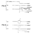
- FIG.4(A) shows a continuous fault.
- the fault detection signal of FIG.4(A) is supplied to the hold processing circuits 24 and 25 through the fault supervisory circuit 21.
- the seizure signal supplied to the seizure supervisory circuit 22 has already been turned ON when the fault detection signal is turned ON at time t1. Therefore, the hold processing circuit 24 continues to output the seizure signal during the predetermined time, 2 to 3 seconds, for example. Then, the hold processing circuit 24 prevents the seizure signal from being supplied to the signalling multiplexer 9.
- This change of the seizure signal is sent to the switch 5b (FIG.1) through the signalling multiplexer 9, the PCM line, and the PCM terminal equipment 1b. Thereby, the related line is set idle and disconnected from the line connection in a conventional way.
- FIG.5(A) shows the case where the answer signal has already been supplied to the answer supervisory circuit 23 when the fault signal shown in FIG.5(A) is turned ON at time t1.
- the answer signal is continuously supplied to the trunk 4a1 from the hold processing circuit 25 in the same way as in the case of the answer signal shown in FIG.4(B).
- FIG.5(C) the seizure signal has already been supplied to the seizure supervisory circuit 22 when the fault signal shown in FIG.5(A) is turned ON at time t1. Since the fault occurs during the time T shorter than the predetermined time, the hold processing circuit 24 continuously outputs the seizure signal.
- broken lines show corresponding signal changes in the conventional method.
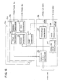
- FIG.6 illustrates an example of the structure for the multiplexer unit 2b and the channel unit 3b1 provided in the PCM terminal equipment 1b.
- the multiplexer unit 2b includes a voice multiplexer 37, a voice demultiplexer 38, and signalling circuits 39 and 40. Each of those circuits can operate in the same way as the corresponding circuit shown in FIG.3.
- the channel unit 3b1 includes a fault supervisory circuit 31, a seizure supervisory circuit 32, an answer supervisory circuit 33, and hold processing circuits 34 and 35, in the same way as the channel unit 3a1 shown in FIG.3. Each of those circuits 31 to 35 can operate in the same way as corresponding circuit shown in FIG.3.
- the seizure supervisory circuit 32 receives a seizure signal from the signalling demultiplexer 10, and sends it to the hold processing circuit 35.
- the seizure signal from the hold processing circuit 35 is supplied to the trunk 4b1 in the same way as in the case of FIG.3.
- An answer signal is supplied to the answer supervisory circuit 33 from the trunk 4b1.
- the channel unit 3b1 operates as shown in FIGS.4 and 5.
- the other channel units may be constructed in the same way as the above-mentioned channel unit 3b1.
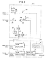
- the fault supervisory circuit 21 includes a relay ALM having a couple of two-position switches 'alm'.
- the seizure supervisory circuit 22 includes a relay SEZ connected to a positive power source.
- the relay SEZ has three make contacts 'sez'.
- the hold process circuit 24 includes a timer TM having a break contact 'tm', a relay ALMB having two break contacts 'almb' and one of the make contacts 'sez', which is connected to ground.
- the answer supervisory circuit 23 includes a relay ANS connected to the positive power source, and one of the switches 'alm'
- the relay ANS has two make contacts 'ans'.
- the hold processing circuit 25 includes one of the make contacts 'ans' connected to ground.
- break and make contacts are simply referred to as contacts.
- the seizure signal from the trunk 4a1 is changed to ground level, and applied to the relay SEZ through the contact 'alm'. It is now assumed that at this time, no fault is detected by the voice demultiplexer 8.
- the relay ALM is supplied with the fault detection signal held at the positive power source level (hereinafter simply referred to a positive level), and its contacts 'alm' are held closed.
- the relay SEZ is a relay having a timer circuit, and holds the previous state thereof during a fixed time after a fault occurs.
- the seizure signal is supplied to the signalling circuit 9, and is then sent to the PCM terminal equipment 1b and the switch 5b.
- the fault detection signal is supplied to the fault supervisory circuit 21 from the voice demultiplexer 8 after the seizure signal is turned ON. At this time, the fault detection signal is switched to ground level. Thereby, the relay ALM starts operating, and the contacts thereof are made open. Then, the fault detection signal fixed to ground level is supplied to the timer TM through the contacts 'sez' and 'almb'. Thereby, the timer TM starts operating.
- the timer TM is a timer which counts two seconds, which correspond to the aforementioned fixed time. The timer TM makes its contact 'tm' open when the fault detection signal is supplied thereto, and then makes the contact 'tm' closed after the lapse of two seconds.
- the relay ALMB does not operate until the timer TM is turned ON. Therefore, the relay SEZ is continuously supplied with ground level through the contacts 'almb', 'sez' and 'alm'. Thus, the seizure signal is continuously supplied to the signalling multiplexer 9.
- the answer signal When the answer signal is turned ON, it is switched to ground level.
- the answer signal When no fault is detected by the voice demultiplexer 8, the answer signal is supplied to the relay ANS through the contact 'alm'. Thereby the contact 'ans' of the relay ANS is made closed, and the answer signal is supplied to the trunk 4a1. Thereafter if the fault detection signal is turned ON, the relay ALM starts operating.
- the relay ANS includes a timer circuit, and therefore can maintain its previous state for a while after the relay ALM is turned ON. Therefore, even when the relay ANS is supplied with ground level through the contact 'ans', the relay ANS is continuously held ON. As a result, the trunk 4a1 is continuously supplied with the answer signal.
- the above-mentioned operation corresponds to the operation illustrated in FIGS.4(A), 4(B), 5(A) and 5(B).
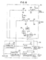
- FIG.8 illustrates an example of the structure for the channel unit 3b1 provided in the PCM terminal equipment 1b.
- the channel unit 3b1 includes the same structural elements as the channel unit 3a1, and operates in the same way as the channel unit 3a1.
- the fault supervisory circuit 31 includes a relay ALM having a couple of two-position switches 'alm'.
- the seizure supervisory circuit 32 includes a relay SEZ connected to a positive power source.
- the relay SEZ has three make contacts 'sez'.
- the hold process circuit 34 includes a timer TM having a break contact 'tm', a relay ALMB having two break contacts 'almb' and one of the make contacts 'sez', which is connected to ground.
- the answer supervisory circuit 33 includes a relay ANS connected to the positive power source, and one of the switches 'alm'.
- the relay ANS has two make contacts 'ans'.
- the hold processing circuit 35 includes one of the make contacts 'ans' connected to ground
- the seizure signal from the signalling demultiplexer 40 is supplied to the relay SEZ through the contact 'alm', and is supplied to the trunk 4b1 through the contact 'sez'.
- the answer signal from the trunk 4b1 is supplied to the relay ANS through the contact 'alm', and to the signalling multiplexer 39 through the contact 'ans'.
- the PCM terminal equipment 1a includes the structure shown in FIGS.6 and 8, and on the other hand, the PCM terminal equipment 1b includes the structure shown in FIGS.3 and 7. In the alternative, it is possible to form the essential part of the channel units shown in FIGS.3, 6 to 8 by software.
- the predetermined time during which the seizure signal is maintained ON is not limited to 2 seconds.
- the predetermined time may be set equal to a time during which it is desired that said seizure signal is continuously supplied to said means even if said fault occurs.
Landscapes
- Engineering & Computer Science (AREA)
- Signal Processing (AREA)
- Computer Networks & Wireless Communication (AREA)
- Time-Division Multiplex Systems (AREA)
- Data Exchanges In Wide-Area Networks (AREA)
- Monitoring And Testing Of Exchanges (AREA)
Applications Claiming Priority (2)
| Application Number | Priority Date | Filing Date | Title |
|---|---|---|---|
| JP63119484A JPH01289333A (ja) | 1988-05-17 | 1988-05-17 | 障害時の呼処理方式 |
| JP119484/88 | 1988-05-17 |
Publications (3)
| Publication Number | Publication Date |
|---|---|
| EP0342593A2 true EP0342593A2 (de) | 1989-11-23 |
| EP0342593A3 EP0342593A3 (de) | 1990-11-22 |
| EP0342593B1 EP0342593B1 (de) | 1997-12-10 |
Family
ID=14762422
Family Applications (1)
| Application Number | Title | Priority Date | Filing Date |
|---|---|---|---|
| EP89108758A Expired - Lifetime EP0342593B1 (de) | 1988-05-17 | 1989-05-16 | Pulskodenmoduliertes Endstellengerät |
Country Status (5)
| Country | Link |
|---|---|
| US (1) | US4912699A (de) |
| EP (1) | EP0342593B1 (de) |
| JP (1) | JPH01289333A (de) |
| CA (1) | CA1320553C (de) |
| DE (1) | DE68928479T2 (de) |
Family Cites Families (8)
| Publication number | Priority date | Publication date | Assignee | Title |
|---|---|---|---|---|
| US3715503A (en) * | 1971-02-16 | 1973-02-06 | Stromberg Carlson Corp | Automatic transfer arrangement for telephone system |
| US3851311A (en) * | 1973-09-17 | 1974-11-26 | Gte Automatic Electric Lab Inc | Arrangement and method for protecting a common highway from false signals |
| JPS5854704B2 (ja) * | 1978-08-11 | 1983-12-06 | 富士通株式会社 | 電子交換機のネツトワ−ク疑似障害検知方式 |
| JPS5842261A (ja) * | 1981-09-07 | 1983-03-11 | Mitsubishi Electric Corp | 機能回路の放熱方法 |
| JPS58109442A (ja) * | 1981-12-22 | 1983-06-29 | Toa Nenryo Kogyo Kk | カルボニル化合物の製造方法 |
| US4558317A (en) * | 1982-11-17 | 1985-12-10 | Paradyne Corporation | Digital communication link monitoring device |
| JPS60214147A (ja) * | 1984-04-09 | 1985-10-26 | Fujitsu Ltd | E線への信号送出装置 |
| US4920921A (en) * | 1988-04-01 | 1990-05-01 | Ochs Gordon M | Modular aquaculture fish pen assembly with slidable divider |
-
1988
- 1988-05-17 JP JP63119484A patent/JPH01289333A/ja active Pending
-
1989
- 1989-05-16 US US07/352,403 patent/US4912699A/en not_active Expired - Lifetime
- 1989-05-16 EP EP89108758A patent/EP0342593B1/de not_active Expired - Lifetime
- 1989-05-16 CA CA000599841A patent/CA1320553C/en not_active Expired - Fee Related
- 1989-05-16 DE DE68928479T patent/DE68928479T2/de not_active Expired - Fee Related
Also Published As
| Publication number | Publication date |
|---|---|
| DE68928479D1 (de) | 1998-01-22 |
| US4912699A (en) | 1990-03-27 |
| EP0342593A3 (de) | 1990-11-22 |
| CA1320553C (en) | 1993-07-20 |
| JPH01289333A (ja) | 1989-11-21 |
| DE68928479T2 (de) | 1998-04-30 |
| EP0342593B1 (de) | 1997-12-10 |
Similar Documents
| Publication | Publication Date | Title |
|---|---|---|
| CA1274009A (en) | Tdma communication system having common local path medium and local time slot for intraoffice calls | |
| US5418776A (en) | Emergency local switching | |
| US4215243A (en) | Automatic modem identification system | |
| US4922484A (en) | ISDN remote switching unit for accommodating analog and digital lines | |
| NZ196421A (en) | Terminal units for subscriber and exchange line circuits in digital t.d.m.telephony system:main and subchannel formed on line | |
| WO1998028901A3 (en) | Distributed voice processing system | |
| US5303239A (en) | Telephone system | |
| US4912699A (en) | Pulse code modulation terminal equipment | |
| US5548584A (en) | Telephone switching system with switched line circuits | |
| CA1184638A (en) | Arrangement for multiple custom calling | |
| GB2072464A (en) | Line supplied telephone interface | |
| US5157715A (en) | Call status recognition in a broadband private automatic branch exchange | |
| CA1184639A (en) | Arrangement for multiple custom calling | |
| EP0331531B1 (de) | Telefonapparat und Steuerungsverfahren dafür | |
| KR100453744B1 (ko) | 음성 녹취 시스템의 수신 발신 겸용 음성 처리 보드 | |
| JPH05110582A (ja) | 音声呼の無切断通信方法 | |
| JPH03274952A (ja) | モデムプーリングシステム | |
| KR0175731B1 (ko) | 광가입자 전송 시스팀 타합 장치 | |
| JPH02226948A (ja) | 発信者限定音声多重化方式 | |
| JPH03135148A (ja) | 同時通信発信接続制御方式 | |
| JPH02295329A (ja) | 加入者収容交換装置 | |
| JPH10108227A (ja) | 構内交換機と無線サービス提供装置との相互接続装置 | |
| JPH06165273A (ja) | 過負荷制御pcm端局装置 | |
| JPS6374248A (ja) | 周波数分割多重回線を収容する電話交換装置 | |
| JPH02308650A (ja) | 端末装置 |
Legal Events
| Date | Code | Title | Description |
|---|---|---|---|
| PUAI | Public reference made under article 153(3) epc to a published international application that has entered the european phase |
Free format text: ORIGINAL CODE: 0009012 |
|
| AK | Designated contracting states |
Kind code of ref document: A2 Designated state(s): DE FR GB SE |
|
| PUAL | Search report despatched |
Free format text: ORIGINAL CODE: 0009013 |
|
| AK | Designated contracting states |
Kind code of ref document: A3 Designated state(s): DE FR GB SE |
|
| RHK1 | Main classification (correction) |
Ipc: H04B 1/74 |
|
| 17P | Request for examination filed |
Effective date: 19901221 |
|
| 17Q | First examination report despatched |
Effective date: 19930108 |
|
| GRAG | Despatch of communication of intention to grant |
Free format text: ORIGINAL CODE: EPIDOS AGRA |
|
| GRAG | Despatch of communication of intention to grant |
Free format text: ORIGINAL CODE: EPIDOS AGRA |
|
| GRAH | Despatch of communication of intention to grant a patent |
Free format text: ORIGINAL CODE: EPIDOS IGRA |
|
| RBV | Designated contracting states (corrected) |
Designated state(s): DE FR GB |
|
| GRAH | Despatch of communication of intention to grant a patent |
Free format text: ORIGINAL CODE: EPIDOS IGRA |
|
| GRAA | (expected) grant |
Free format text: ORIGINAL CODE: 0009210 |
|
| AK | Designated contracting states |
Kind code of ref document: B1 Designated state(s): DE FR GB |
|
| REF | Corresponds to: |
Ref document number: 68928479 Country of ref document: DE Date of ref document: 19980122 |
|
| ET | Fr: translation filed | ||
| PLBE | No opposition filed within time limit |
Free format text: ORIGINAL CODE: 0009261 |
|
| STAA | Information on the status of an ep patent application or granted ep patent |
Free format text: STATUS: NO OPPOSITION FILED WITHIN TIME LIMIT |
|
| 26N | No opposition filed | ||
| REG | Reference to a national code |
Ref country code: GB Ref legal event code: IF02 |
|
| PGFP | Annual fee paid to national office [announced via postgrant information from national office to epo] |
Ref country code: FR Payment date: 20040510 Year of fee payment: 16 |
|
| PGFP | Annual fee paid to national office [announced via postgrant information from national office to epo] |
Ref country code: GB Payment date: 20040512 Year of fee payment: 16 |
|
| PGFP | Annual fee paid to national office [announced via postgrant information from national office to epo] |
Ref country code: DE Payment date: 20040527 Year of fee payment: 16 |
|
| PG25 | Lapsed in a contracting state [announced via postgrant information from national office to epo] |
Ref country code: GB Free format text: LAPSE BECAUSE OF NON-PAYMENT OF DUE FEES Effective date: 20050516 |
|
| PG25 | Lapsed in a contracting state [announced via postgrant information from national office to epo] |
Ref country code: DE Free format text: LAPSE BECAUSE OF NON-PAYMENT OF DUE FEES Effective date: 20051201 |
|
| GBPC | Gb: european patent ceased through non-payment of renewal fee |
Effective date: 20050516 |
|
| PG25 | Lapsed in a contracting state [announced via postgrant information from national office to epo] |
Ref country code: FR Free format text: LAPSE BECAUSE OF NON-PAYMENT OF DUE FEES Effective date: 20060131 |
|
| REG | Reference to a national code |
Ref country code: FR Ref legal event code: ST Effective date: 20060131 |