EP0342431B1 - Unité de butée de débrayage pour un embrayage poussé de véhicule automobile - Google Patents
Unité de butée de débrayage pour un embrayage poussé de véhicule automobile Download PDFInfo
- Publication number
- EP0342431B1 EP0342431B1 EP89107982A EP89107982A EP0342431B1 EP 0342431 B1 EP0342431 B1 EP 0342431B1 EP 89107982 A EP89107982 A EP 89107982A EP 89107982 A EP89107982 A EP 89107982A EP 0342431 B1 EP0342431 B1 EP 0342431B1
- Authority
- EP
- European Patent Office
- Prior art keywords
- release bearing
- housing
- bearing device
- sliding sleeve
- clutch
- Prior art date
- Legal status (The legal status is an assumption and is not a legal conclusion. Google has not performed a legal analysis and makes no representation as to the accuracy of the status listed.)
- Expired - Lifetime
Links
Images


Classifications
-
- F—MECHANICAL ENGINEERING; LIGHTING; HEATING; WEAPONS; BLASTING
- F16—ENGINEERING ELEMENTS AND UNITS; GENERAL MEASURES FOR PRODUCING AND MAINTAINING EFFECTIVE FUNCTIONING OF MACHINES OR INSTALLATIONS; THERMAL INSULATION IN GENERAL
- F16D—COUPLINGS FOR TRANSMITTING ROTATION; CLUTCHES; BRAKES
- F16D23/00—Details of mechanically-actuated clutches not specific for one distinct type
- F16D23/12—Mechanical clutch-actuating mechanisms arranged outside the clutch as such
- F16D23/14—Clutch-actuating sleeves or bearings; Actuating members directly connected to clutch-actuating sleeves or bearings
Definitions
- the invention relates to a release bearing device for a depressed motor vehicle clutch, on the one hand engages a clutch lever via a housing of a release bearing and on the other hand spring tongues of a clutch actuator spring, the housing being axially displaceably guided on a transmission-fixed guide tube.
- Such a release bearing device for a pressed motor vehicle clutch is described in DE-A-3612419.
- the depressed motor vehicle clutch is uncoupled in that the clutch lever presses on the clutch actuator springs via the release bearing.
- the clutch lever is acted upon at one end by an actuating means for uncoupling. Its other end is supported at a pivot point which is designed as a damping element in DE-A-3612419 in order to dampen vibrations of the clutch lever in the engaged state.
- the release bearing is constantly pressed against the diaphragm spring with a slight preload, so that the release bearing is constantly in motion coupled state of the clutch rotates.
- vibrations of the crankshaft and alignment tolerances between the crankshaft and the transmission shaft and the clutch actuator spring are transmitted to the release bearing as wobbling movements.
- This increases its wear. Due to an eccentric to the release bearing on the clutch lever, creating the preload, the wear can only be reduced to a limited extent, since the preload in turn acts eccentrically on the release bearing, which can even favor the wobbling movements of the release bearing.
- the object of the invention is to propose a release bearing device of the type mentioned in the introduction which creates a preload for the contact between the release bearing and the clutch actuator spring, which acts concentrically on the release bearing.
- the above object is achieved in a release bearing device of the type mentioned at the outset in that an axially displaceable sliding sleeve is arranged on the housing, in that a compression spring is effective between an abutment surface of the housing and a collar of the sliding sleeve and that in the coupled state the Coupling the sliding sleeve finds a gear-fixed stop, whereby the compression spring concentrically presses the release bearing against the spring tongues of the clutch actuator spring via the housing.
- the compression spring has no effect when disengaged. It is not burdened by the forces that occur when disengaging.
- the arrangement of the sliding sleeve supporting the compression spring on the housing ensures that the release bearing with its housing and the sliding sleeve and the compression spring form a structural unit which can be easily assembled.
- the sliding sleeve encloses the guide tube. Your space requirement is therefore small. It takes up a free space on the guide tube, which means no particular restriction for the length of the sliding sleeve and thus the length of the compression spring. If the guide tube has a flange, then in a preferred embodiment of the invention the collar strikes the flange in the coupled state.
- the sliding sleeve In order to hold the sliding sleeve and thus also the compression spring captively on the housing of the release bearing, the sliding sleeve preferably has a projection on its end facing away from the collar, which is opposite an edge of the housing which faces away from the contact surface of the compression spring, in the coupled state there is a margin between the molding and the edge.
- a wall covering the compression spring is formed on the sliding sleeve, which engages in a recess of the housing and is displaceable therein.
- the compression spring is thus encapsulated on the device.
- the device described can be used in motor vehicle clutches both with hydraulic actuation and with purely mechanical actuation of the clutch lever.
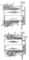
- a clutch (1) has spring tongues (2) of a clutch actuator spring that run around with a crankshaft (not shown). These rest on an inner ring (3) of a release bearing (4), the outer ring (5) of which is connected to a housing (6). Between rolling elements (7) are arranged on the inner ring (3) and the outer ring (5).
- a clutch lever (9) bears on a region (8) facing away from the inner ring (3). This is supported at one end at a pivot point (10). An actuating means (11) engages at its other end.
- the housing (6) with the outer ring (5) and the inner ring (3) is displaceable in relation to a guide tube (12) which is fastened to a gear housing (14) by means of a flange (13).
- a transmission shaft (15) extends through the guide tube (12) into the coupling (1).
- a sliding sleeve (17) surrounding this is displaceably mounted on the guide tube (12).
- the sliding sleeve (17) extends between the housing (6) and the guide tube (12), the housing (6) being displaceably guided on the sliding sleeve (17).
- the sliding sleeve (17) has a collar (18).
- a coiled compression spring (20) is arranged between the collar (18) and a contact surface (19) of the housing (6).
- the sliding sleeve (17) consists of steel or a polymeric material.
- the sliding sleeve (17) is attached to the housing (6) by a molding (21) which faces an edge (22) of the housing (6) which is provided on the side of the housing (6) facing away from the compression spring (20). kept captive. If the sliding sleeve (17) is made of steel, then the molded part (21) is a flange. If it consists of a polymeric material, then the molding (21) can be formed by snap noses.
- a wall (23) covering the compression spring (20) on the outside is formed on the sliding sleeve (17).
- the wall (23) engages in a recess (24) in the housing (6).
- the collar (18) does not find a stop on the flange (13).
- the compression spring (20) presses the sliding sleeve (17) in the direction of arrow (b) until the molding (21) of the sliding sleeve (17) strikes the edge (22) of the housing (6).
- the sliding sleeve (17) is thus braced against the housing (6), so that it cannot perform any free movements in relation to it.
- the compression spring (20) has no effect on the uncoupled state. It is not burdened by the forces that occur when uncoupling.
- the wall (23) and the recess (24) are dimensioned such that the wall (23) still engages in the recess (24) when the molded part (21) strikes the edge (22). 20) is also encapsulated in this position in relation to the environment.
- the clutch actuator spring pushes the housing (6) further in the direction of the flange (13) via the inner ring (3) (cf. FIG. 4).
- the wall (23) increasingly enters the recess (24) and the compression spring (20) continues to tension.
- the device described thus adjusts itself automatically to the wear of the clutch lining without the need for mechanical readjustment.
- the possible stroke (H) of the wall (23) in the recess (24) until the wall (23) strikes the contact surface (19) is dimensioned such that the wall (23) only on the contact surface when the clutch lining is completely worn (19) hits (see Figure 4).
Landscapes
- Engineering & Computer Science (AREA)
- General Engineering & Computer Science (AREA)
- Mechanical Engineering (AREA)
- Mechanical Operated Clutches (AREA)
Claims (9)
Applications Claiming Priority (2)
| Application Number | Priority Date | Filing Date | Title |
|---|---|---|---|
| DE3816890A DE3816890A1 (de) | 1988-05-18 | 1988-05-18 | Ausruecklagereinrichtung fuer eine gedrueckte kraftfahrzeugkupplung |
| DE3816890 | 1988-05-18 |
Publications (2)
| Publication Number | Publication Date |
|---|---|
| EP0342431A1 EP0342431A1 (fr) | 1989-11-23 |
| EP0342431B1 true EP0342431B1 (fr) | 1991-07-24 |
Family
ID=6354615
Family Applications (1)
| Application Number | Title | Priority Date | Filing Date |
|---|---|---|---|
| EP89107982A Expired - Lifetime EP0342431B1 (fr) | 1988-05-18 | 1989-05-03 | Unité de butée de débrayage pour un embrayage poussé de véhicule automobile |
Country Status (6)
| Country | Link |
|---|---|
| US (1) | US4911277A (fr) |
| EP (1) | EP0342431B1 (fr) |
| JP (1) | JPH0211929A (fr) |
| BR (1) | BR8902247A (fr) |
| DE (2) | DE3816890A1 (fr) |
| ES (1) | ES2023023B3 (fr) |
Families Citing this family (5)
| Publication number | Priority date | Publication date | Assignee | Title |
|---|---|---|---|---|
| FR2682441B1 (fr) * | 1991-10-15 | 1993-12-10 | Procal | Tube-guide a etancheite integree pour butee de debrayage de boite de vitesses de vehicule automobile. |
| DE4224179C1 (de) * | 1992-07-22 | 1993-11-11 | Freudenberg Carl Fa | Führungshülse mit integrierter Dichtung für ein Kupplungsausrücklager eines Getriebes |
| ES2123065T3 (es) * | 1992-08-25 | 1999-01-01 | Searle & Co | Hidroxietilamino-sulfonamidas utiles como inhibidores de proteasas retroviricas. |
| CN101876354B (zh) * | 2010-06-18 | 2011-09-28 | 广东福迪汽车有限公司 | 带有轴向缓冲功能的离合器控制装置 |
| CN111022521A (zh) * | 2019-11-26 | 2020-04-17 | 温州天纳福汽车轴承股份有限公司 | 一种高耐压推式液压分离轴承 |
Family Cites Families (14)
| Publication number | Priority date | Publication date | Assignee | Title |
|---|---|---|---|---|
| US2703164A (en) * | 1950-04-13 | 1955-03-01 | Binder Richard | Automatic wear compensator |
| FR1429359A (fr) * | 1965-01-12 | 1966-02-18 | Ferodo Sa | Perfectionnements aux butées de débrayage |
| US3376964A (en) * | 1966-07-26 | 1968-04-09 | Lipe Rollway Corp | Self-adjusting clutch |
| US3478853A (en) * | 1968-01-08 | 1969-11-18 | Borg Warner | Automatic wear adjuster for friction device |
| DE2221231C3 (de) * | 1972-04-29 | 1981-12-10 | LuK Lamellen und Kupplungsbau GmbH, 7580 Bühl | Selbstzentrierendes Kupplungsausrücklager |
| JPS5824652B2 (ja) * | 1972-10-18 | 1983-05-23 | エス カ−ル エフ インダストリアル トレイデイング アンド デベロツプメント カンパニイ ビ−ヴイ | シンアワセクラツチジクウケ |
| DE2524233C2 (de) * | 1975-05-31 | 1985-10-10 | SKF GmbH, 8720 Schweinfurt | Kupplungsausrücker für Membranfederkupplungen |
| US4057134A (en) * | 1976-05-28 | 1977-11-08 | Borg-Warner Corporation | Automatic clutch wear adjuster |
| FR2510689A1 (fr) * | 1981-07-30 | 1983-02-04 | Valeo | Butee de debrayage, notamment pour vehicule automobile |
| DE3326107A1 (de) * | 1983-07-20 | 1985-01-31 | Fichtel & Sachs Ag, 8720 Schweinfurt | Hydraulisch betaetigbarer kupplungsausruecker |
| US4660702A (en) * | 1985-04-24 | 1987-04-28 | Dana Corporation | Clutch release bearing |
| US4687084A (en) * | 1985-07-22 | 1987-08-18 | Automotive Products Plc | Clutch release apparatus for pull type clutches |
| DE3612419A1 (de) * | 1986-04-12 | 1987-10-22 | Schaeffler Waelzlager Kg | Lagerung eines kupplungshebels an kraftfahrzeugen |
| US4808015A (en) * | 1987-10-06 | 1989-02-28 | Federal-Mogul Corporation | Clutch release bearing assembly including a double-acting sliding bore sleeve |
-
1988
- 1988-05-18 DE DE3816890A patent/DE3816890A1/de not_active Withdrawn
-
1989
- 1989-04-14 US US07/343,874 patent/US4911277A/en not_active Expired - Fee Related
- 1989-05-03 DE DE8989107982T patent/DE58900187D1/de not_active Expired - Lifetime
- 1989-05-03 EP EP89107982A patent/EP0342431B1/fr not_active Expired - Lifetime
- 1989-05-03 ES ES89107982T patent/ES2023023B3/es not_active Expired - Lifetime
- 1989-05-15 BR BR898902247A patent/BR8902247A/pt not_active IP Right Cessation
- 1989-05-16 JP JP1120582A patent/JPH0211929A/ja active Pending
Also Published As
| Publication number | Publication date |
|---|---|
| US4911277A (en) | 1990-03-27 |
| BR8902247A (pt) | 1990-01-09 |
| DE58900187D1 (de) | 1991-08-29 |
| EP0342431A1 (fr) | 1989-11-23 |
| JPH0211929A (ja) | 1990-01-17 |
| ES2023023B3 (es) | 1991-12-16 |
| DE3816890A1 (de) | 1989-11-30 |
Similar Documents
| Publication | Publication Date | Title |
|---|---|---|
| DE112008002517B4 (de) | Kupplungsbetätigungssystem | |
| EP2145118B1 (fr) | Unité d'actionnement d'embrayage en fonction d'une différence couple/vitesse pour véhicules à moteur | |
| DE4440412A1 (de) | Reibungskupplung mit automatischem Verschleißausgleich | |
| WO2019196978A1 (fr) | Amortisseur de vibrations de torsion | |
| DE102016211217B3 (de) | Fliehkraftkupplung mit reibungsminimiertem Koppelbolzen und Antriebsstrang | |
| DE2029334A1 (de) | Reibungskupplung | |
| DE4403477C1 (de) | Wellenkupplung | |
| EP0342431B1 (fr) | Unité de butée de débrayage pour un embrayage poussé de véhicule automobile | |
| DE10114844A1 (de) | Selbsteinstellendes Kupplungsausrücklager | |
| EP1862688B1 (fr) | Agencement de transmission d'un couple de rotation pour le conducteur de commande d'un véhicule | |
| DE2804053A1 (de) | Kupplungs- und daempfereinheit | |
| DE102008027056A1 (de) | Reibungskupplung | |
| DE202008006078U1 (de) | Torsionsschwingungsdämpfer | |
| EP2880325A1 (fr) | Double embrayage | |
| DE2242140A1 (de) | Ausruecklager fuer reibungskupplungen mit gegen axialblattfeder radial in einem gehaeuse verschiebbarem lager | |
| WO2011020456A1 (fr) | Cloison et boîte de vitesses de véhicule à moteur | |
| EP0950825B1 (fr) | Unité de débrayage pour plateau de pression d'un embrayage et commande de la même | |
| DE102014212193A1 (de) | Kupplungsausrücksystem | |
| DE102011087101A1 (de) | Ausrücksystem zur hydraulischen Betätigung einer Kupplung | |
| EP3692273B1 (fr) | Système de couplage | |
| DE102009046599A1 (de) | Reibungskupplung für ein Kraftfahrzeug mit einer Einrichtung zum Dämpfen von Axialschwingungen | |
| DE102009042829A1 (de) | Ausrücksystem für Kupplungen | |
| DE10059226C1 (de) | Dämpfungseinrichtung für eine drehelastische Kupplung | |
| DE3329039A1 (de) | Reibungskupplung in gedrueckter bauweise ohne anlagewechsel der membranfeder | |
| DE10154668B4 (de) | Kupplung für ein Kraftfahrzeug |
Legal Events
| Date | Code | Title | Description |
|---|---|---|---|
| PUAI | Public reference made under article 153(3) epc to a published international application that has entered the european phase |
Free format text: ORIGINAL CODE: 0009012 |
|
| 17P | Request for examination filed |
Effective date: 19890503 |
|
| AK | Designated contracting states |
Kind code of ref document: A1 Designated state(s): DE ES FR GB IT |
|
| 17Q | First examination report despatched |
Effective date: 19901221 |
|
| ITF | It: translation for a ep patent filed | ||
| GRAA | (expected) grant |
Free format text: ORIGINAL CODE: 0009210 |
|
| AK | Designated contracting states |
Kind code of ref document: B1 Designated state(s): DE ES FR GB IT |
|
| GBT | Gb: translation of ep patent filed (gb section 77(6)(a)/1977) | ||
| REF | Corresponds to: |
Ref document number: 58900187 Country of ref document: DE Date of ref document: 19910829 |
|
| ET | Fr: translation filed | ||
| PGFP | Annual fee paid to national office [announced via postgrant information from national office to epo] |
Ref country code: FR Payment date: 19920324 Year of fee payment: 4 |
|
| PGFP | Annual fee paid to national office [announced via postgrant information from national office to epo] |
Ref country code: ES Payment date: 19920508 Year of fee payment: 4 |
|
| PLBE | No opposition filed within time limit |
Free format text: ORIGINAL CODE: 0009261 |
|
| STAA | Information on the status of an ep patent application or granted ep patent |
Free format text: STATUS: NO OPPOSITION FILED WITHIN TIME LIMIT |
|
| 26N | No opposition filed | ||
| PG25 | Lapsed in a contracting state [announced via postgrant information from national office to epo] |
Ref country code: GB Effective date: 19930503 |
|
| PG25 | Lapsed in a contracting state [announced via postgrant information from national office to epo] |
Ref country code: ES Free format text: LAPSE BECAUSE OF NON-PAYMENT OF DUE FEES Effective date: 19930504 |
|
| GBPC | Gb: european patent ceased through non-payment of renewal fee |
Effective date: 19930503 |
|
| PG25 | Lapsed in a contracting state [announced via postgrant information from national office to epo] |
Ref country code: FR Effective date: 19940131 |
|
| REG | Reference to a national code |
Ref country code: FR Ref legal event code: ST |
|
| PGFP | Annual fee paid to national office [announced via postgrant information from national office to epo] |
Ref country code: DE Payment date: 19940525 Year of fee payment: 6 |
|
| PG25 | Lapsed in a contracting state [announced via postgrant information from national office to epo] |
Ref country code: DE Effective date: 19960201 |
|
| REG | Reference to a national code |
Ref country code: ES Ref legal event code: FD2A Effective date: 19990405 |
|
| PG25 | Lapsed in a contracting state [announced via postgrant information from national office to epo] |
Ref country code: IT Free format text: LAPSE BECAUSE OF NON-PAYMENT OF DUE FEES;WARNING: LAPSES OF ITALIAN PATENTS WITH EFFECTIVE DATE BEFORE 2007 MAY HAVE OCCURRED AT ANY TIME BEFORE 2007. THE CORRECT EFFECTIVE DATE MAY BE DIFFERENT FROM THE ONE RECORDED. Effective date: 20050503 |