EP0342350A2 - Durch Handkraft höhenverstellbare Kraftfahrzeuglenksäule - Google Patents
Durch Handkraft höhenverstellbare Kraftfahrzeuglenksäule Download PDFInfo
- Publication number
- EP0342350A2 EP0342350A2 EP89106247A EP89106247A EP0342350A2 EP 0342350 A2 EP0342350 A2 EP 0342350A2 EP 89106247 A EP89106247 A EP 89106247A EP 89106247 A EP89106247 A EP 89106247A EP 0342350 A2 EP0342350 A2 EP 0342350A2
- Authority
- EP
- European Patent Office
- Prior art keywords
- inner tube
- sliding
- steering column
- tube
- torsion bar
- Prior art date
- Legal status (The legal status is an assumption and is not a legal conclusion. Google has not performed a legal analysis and makes no representation as to the accuracy of the status listed.)
- Granted
Links
- 238000006073 displacement reaction Methods 0.000 claims abstract description 6
- 238000004519 manufacturing process Methods 0.000 description 4
- 238000002347 injection Methods 0.000 description 2
- 239000007924 injection Substances 0.000 description 2
- 238000005266 casting Methods 0.000 description 1
- 238000003466 welding Methods 0.000 description 1
Images
Classifications
-
- B—PERFORMING OPERATIONS; TRANSPORTING
- B62—LAND VEHICLES FOR TRAVELLING OTHERWISE THAN ON RAILS
- B62D—MOTOR VEHICLES; TRAILERS
- B62D1/00—Steering controls, i.e. means for initiating a change of direction of the vehicle
- B62D1/02—Steering controls, i.e. means for initiating a change of direction of the vehicle vehicle-mounted
- B62D1/16—Steering columns
- B62D1/18—Steering columns yieldable or adjustable, e.g. tiltable
- B62D1/185—Steering columns yieldable or adjustable, e.g. tiltable adjustable by axial displacement, e.g. telescopically
-
- F—MECHANICAL ENGINEERING; LIGHTING; HEATING; WEAPONS; BLASTING
- F16—ENGINEERING ELEMENTS AND UNITS; GENERAL MEASURES FOR PRODUCING AND MAINTAINING EFFECTIVE FUNCTIONING OF MACHINES OR INSTALLATIONS; THERMAL INSULATION IN GENERAL
- F16B—DEVICES FOR FASTENING OR SECURING CONSTRUCTIONAL ELEMENTS OR MACHINE PARTS TOGETHER, e.g. NAILS, BOLTS, CIRCLIPS, CLAMPS, CLIPS OR WEDGES; JOINTS OR JOINTING
- F16B7/00—Connections of rods or tubes, e.g. of non-circular section, mutually, including resilient connections
- F16B7/10—Telescoping systems
- F16B7/14—Telescoping systems locking in intermediate non-discrete positions
-
- F—MECHANICAL ENGINEERING; LIGHTING; HEATING; WEAPONS; BLASTING
- F16—ENGINEERING ELEMENTS AND UNITS; GENERAL MEASURES FOR PRODUCING AND MAINTAINING EFFECTIVE FUNCTIONING OF MACHINES OR INSTALLATIONS; THERMAL INSULATION IN GENERAL
- F16C—SHAFTS; FLEXIBLE SHAFTS; ELEMENTS OR CRANKSHAFT MECHANISMS; ROTARY BODIES OTHER THAN GEARING ELEMENTS; BEARINGS
- F16C3/00—Shafts; Axles; Cranks; Eccentrics
- F16C3/02—Shafts; Axles
- F16C3/03—Shafts; Axles telescopic
-
- F—MECHANICAL ENGINEERING; LIGHTING; HEATING; WEAPONS; BLASTING
- F16—ENGINEERING ELEMENTS AND UNITS; GENERAL MEASURES FOR PRODUCING AND MAINTAINING EFFECTIVE FUNCTIONING OF MACHINES OR INSTALLATIONS; THERMAL INSULATION IN GENERAL
- F16C—SHAFTS; FLEXIBLE SHAFTS; ELEMENTS OR CRANKSHAFT MECHANISMS; ROTARY BODIES OTHER THAN GEARING ELEMENTS; BEARINGS
- F16C2326/00—Articles relating to transporting
- F16C2326/20—Land vehicles
- F16C2326/24—Steering systems, e.g. steering rods or columns
Definitions
- the innovation relates to a motor vehicle steering column which is height-adjustable by hand, with a telescopic tube consisting of an inner and an outer tube, in which two spaced-apart, sprayed-on or cast-on slide bushings equipped with flat sliding surfaces are provided on the inner tube in the area of overlap with the outer tube. which sliding surfaces of the polygonal cross-section in the sliding area are assigned.
- the part of the inner tube lying between the sliding bushes is at Assembly of the inner and outer tubes twisted, so that after assembly of the telescopic tube between the outer and inner tubes there is a frictional connection, which also guarantees a backlash between the parts of the telescopic tube in the direction of rotation of the steering column.
- the innovation is based on the object of increasing the adjustment range between the outer and inner tubes in a motor vehicle steering column of the type mentioned which can be adjusted by hand.
- a sliding bush is provided in the vicinity of an end face of the inner tube and is attached to an end piece of a torsion bar extending into the interior of the inner tube, the end piece lying within the inner tube being connected to the inner tube and that Sliding surfaces of the torsion bar-fixed bushing are offset from the sliding surfaces of a sliding bushing attached to the surface of the inner tube and can be aligned to the sliding surfaces of the outer tube by a rotational deformation of the torsion bar.
- the torsion bar arranged in the interior of the inner tube which is twisted in its elasticity range when the telescopic tube is assembled, results in a small overall length for both sliding bushings and a correspondingly large adjustment range in relation to the outer tube.
- This large adjustment range of the motor vehicle steering column has considerable advantages in the event of an impact of the motor vehicle, since the steering wheel can be moved away by the vehicle driver by taking full advantage of the wide adjustment range by appropriate safety measures.
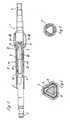
- the motor vehicle steering column 1 is designed as a telescopic tube, which is composed of an outer tube 2 and an inner tube 3.
- a steering wheel is attached to the outer end 4 of the outer tube, while a steering gear is provided at the outer end 5 of the inner tube.
- the outer tube 2 is polygonal in the overlap and displacement area between the outer and inner tubes, specifically triangular in the exemplary embodiment shown.
- a cross-sectional contour corresponding to the outer tube has the inner tube 3, on the surface of which a sliding bush 6 has been cast or injection molded. From Fig. 1 it follows that this sliding bush 6 extends into the vicinity of the front end 7 of the inner tube 3.
- a second sliding bush 8 is provided, which is fixed to an end piece 9 of a torsion bar 10.
- the other end piece 11 of the torsion bar is designed in accordance with the inner contour of the inner tube 3 and thus, as can be seen from FIG. 2, engages in a form-fitting manner in the inner tube.
- An additional fixation of the end piece 11 against an axial displacement within the inner tube takes place by means of a welding point 12 which connects the end piece 11 to the inner tube 3.
- the sliding surfaces of the sliding bush 6 have a slight angular displacement relative to the assigned sliding surfaces of the sliding bush 8.
- the sliding surfaces of the sliding bushes mentioned are aligned with the sliding surfaces of the outer tube, the torsion bar 10, which is preferably round in cross section, being twisted in its elastic range. This results in a play-free connection between the outer and inner tubes in the direction of rotation.
- the end piece 9, onto which the sliding bush 8 is injected or cast, is polygonal in cross section.
- the end face 13 of the sliding bush 8 bears against the end face 7 of the inner tube 3.
Landscapes
- Engineering & Computer Science (AREA)
- General Engineering & Computer Science (AREA)
- Mechanical Engineering (AREA)
- Chemical & Material Sciences (AREA)
- Combustion & Propulsion (AREA)
- Transportation (AREA)
- Ocean & Marine Engineering (AREA)
- Steering Controls (AREA)
Abstract
Description
- Die Neuerung bezieht sich auf eine durch Handkraft höhenverstellbare Kraftfahrzeuglenksäule, mit einem aus einem Innen- und einem Außenrohr bestehenden Teleskoprohr, bei dem am Innenrohr im Überlappungsbereich mit dem Außenrohr zwei in Abstand voneinander angeordnete, aufgespritzte oder aufgegossene, mit ebenen Gleitflächen ausgerüstete Gleitbuchsen vorgesehen sind, denen Gleitflächen des im Verschiebereich im Querschnitt mehreckigen Außenrohres zugeordnet sind.
- Es ist eine durch Handkraft höhenverstellbare Kraftfahrzeuglenksäule dieser Art bekannt (DE-OS 32 02 669), bei der das im Querschnitt mehreckige Innenrohr mit zwei in Abstand voneinander angeordneten, aufgespritzten oder aufgegossenen Gleitbuchsen versehen ist, deren Gleitflächen miteinander fluchten und aufgrund der Fertigung in einem gemeinsamen Gieß- oder Spritzwerkzeuk geringe Fertigungstoleranzen aufweisen, die von den Fertigungsungenauigkeiten und Fertigungstoleranzen des Innenrohres unabhängig sind.
- Der zwischen den Gleitbuchsen liegende Teil des Innenrohres wird beim Zusammenbau des Innen- und des Außenrohres tordiert, so daß nach der Montage des Teleskoprohres zwischen dem Außen- und dem Innenrohr ein Kraftschluß besteht, der auch in der Drehrichtung der Lenksäule eine Spielfreiheit zwischen den Teilen des Teleskoprohres gewährleistet.
- Durch die an der Oberfläche des Innenrohres festgelegten und in einen solchen Abstand voneinander angeordneten Gleitbuchsen, das zwischen den Gleitbuchsen ein Innenrohrteil vorhanden ist, das beim Zusammenbau des Teleskoprohres tordiert werden kann, ergibt sich bei einer vorgegebenen Gesamtlänge der Kraftfahrzeuglenksäule ein entsprechend kleiner Verschiebereich zwischen dem Außenrohr und dem Innenrohr.
- Der Neuerung liegt die Aufgabe zugrunde, bei einer durch Handkraft höhenverstellbaren Kraftfahrzeuglenksäule der eingangs genannten Art den Verstellbereich zwischen dem Außen- und dem Innenrohr zu vergrößern.
- Diese Aufgabe wird nach der Neuerung dadurch gelöst, daß eine Gleitbuchse in der Nähe eines Stirnendes des Innenrohres vorgesehen und an einem Endstück eines sich in den Innenraum des Innenrohres erstreckenden Drehstabs befestigt ist, dessen innerhalb des Innenrohres liegendes Endstück mit dem Innenrohr verbunden ist und daß die Gleitflächen der drehstabfesten Buchse gegenüber den Gleitflächen einer an der Oberfläche des Innenrohres befestigten Gleitbuchse versetzt und durch eine Drehverformung des Drehstabes zu den Gleitflächen des Außenrohres ausrichtbar sind.
- Durch den im Innenraum des Innenrohres angeordneten Drehstab, der beim Zusammenbau des Teleskoprohres in seinem Elastizitätsbereich tordiert wird, ergibt sich für beide Gleitbuchsen eine geringe Baulänge und ein entsprechend großer Verstellbereich gegenüber dem Außenrohr. Dieser große Verstellbereich der Kraftfarzeuglenksäule hat bei einem Aufprall des Kraftfahrzeuges erhebliche Vorteile, da durch entsprechende Sicherheitsmaßnahmen das Lenkrad von dem Fahrzeugführer unter voller Ausnutzung des weiten Verstellbereiches wegbewegt werden kann.
- Weitere Merkmale der Neuerung ergeben sich aus den Unteransprüchen. Ein Ausführungsbeispiel der Neuerung ist in der Zeichnung dargestellt und wird im folgenden beschrieben.
- Es zeigen:
- Fig. 1 eine durch Handkraft höhenverstellbare Kraftfahrzeuglenksäule, und zwar teilweise geschnitten,
- Fig. 2 einen Schnitt nach der Linie II-II in Fig. 1, und zwar in vergrößertem Maßstab und
- Fig. 3 einen Schnitt nach der Linie III-III in Fig. 1.
- Die Kraftfahrzeuglenksäule 1 ist als Teleskoprohr ausgebildet, das sich aus einem Außenrohr 2 und einem Innenrohr 3 zusammensetzt. Am äußeren Ende 4 des Außenrohres wird ein Lenkrad befestigt, während am äußeren Ende 5 des Innenrohres ein Lenkgetriebe vorgesehen wird.
- Aus den Fig. 2 und 3 ergibt sich, daß das Außenrohr 2 im Überlappungs- und Verschiebebereich zwischen dem Außen- und dem Innenrohr mehreckig, und zwar im dargestellten Ausführungsbeispiel dreieckförmig, ausgebildet ist. Eine dem Außenrohr entsprechende Querschnittskotur weist das Innenrohr 3 auf, auf dessen Oberfläche eine Gleitbuchse 6 gegossen oder gespritzt wurde. Aus der Fig. 1 ergibt sich, daß sich diese Gleitbuchse 6 bis in die Nähe des Stirnendes 7 des Innenrohres 3 erstreckt. In der Nähe des Stirnendes 7 des Innenrohres 3, und zwar außerhalb des Innenrohres, ist eine zweite Gleitbuchse 8 vorgesehen, die an einem Endstück 9 eines Drehstabes 10 festgelegt ist. Das andere Endstück 11 des Drehstabes ist entsprechend der Innenkontur des Innenrohres 3 ausgebildet und greift somit, wie dies aus der Fig. 2 zu entnehmen ist, formschlüssig in das Innenrohr ein. Eine zusätzliche Festlegung des Endstücks 11 gegen eine axiale Verschiebung innerhalb des Innenrohres erfolgt durch einen Schweißpunkt 12, der das Endstück 11 mit den Innenrohr 3 verbindet.
- Die Gleitflächen der Gleitbuchse 6 weisen zu den zugeordneten Gleitflächen der Gleitbuchse 8 eine geringe Drehwinkelversetzung auf. Beim Einsetzen des Innenrohres in das Außenrohr wird eine Ausrichtung der Gleitflächen der genannten Gleitbuchsen zu den Gleitflächen des Außenrohres vorgenommen, wobei der Drehstab 10, der vorzugsweise im Querschnitt rund ausgebildet ist, in seinem Elastizitätsbereich tordiert wird. Hierdurch ergibt sich eine spielfreie Verbindung zwischen dem Außen- und dem Innenrohr in Drehrichtung.
- Das Endstück 9, auf das die Gleitbuchse 8 gespritztoder gegossen wird, ist im Querschnitt mehreckig ausgebildet. Die Stirnfläche 13 der Gleitbuchse 8 liegt an der Stirnfläche 7 des Innenrohres 3 an.
Claims (6)
Applications Claiming Priority (2)
| Application Number | Priority Date | Filing Date | Title |
|---|---|---|---|
| DE8806563U | 1988-05-19 | ||
| DE8806563U DE8806563U1 (de) | 1988-05-19 | 1988-05-19 | Durch Handkraft höhenverstellbare Kraftfahrzeuglenksäule |
Publications (3)
| Publication Number | Publication Date |
|---|---|
| EP0342350A2 true EP0342350A2 (de) | 1989-11-23 |
| EP0342350A3 EP0342350A3 (en) | 1990-08-22 |
| EP0342350B1 EP0342350B1 (de) | 1993-10-13 |
Family
ID=6824203
Family Applications (1)
| Application Number | Title | Priority Date | Filing Date |
|---|---|---|---|
| EP89106247A Expired - Lifetime EP0342350B1 (de) | 1988-05-19 | 1989-04-08 | Durch Handkraft höhenverstellbare Kraftfahrzeuglenksäule |
Country Status (5)
| Country | Link |
|---|---|
| US (1) | US4962944A (de) |
| EP (1) | EP0342350B1 (de) |
| DE (1) | DE8806563U1 (de) |
| ES (1) | ES2043929T3 (de) |
| PT (1) | PT90603B (de) |
Cited By (1)
| Publication number | Priority date | Publication date | Assignee | Title |
|---|---|---|---|---|
| EP0446428A3 (en) * | 1990-03-16 | 1992-02-26 | Reiche & Co. | Vehicle steering column, built with telescopic tubes, preferably manually adjustable in length |
Families Citing this family (9)
| Publication number | Priority date | Publication date | Assignee | Title |
|---|---|---|---|---|
| JP2666557B2 (ja) * | 1990-10-15 | 1997-10-22 | トヨタ自動車株式会社 | エバポパージシステムの故障診断装置 |
| GB2253024A (en) * | 1991-02-20 | 1992-08-26 | Torrington Co | Adjustable reach, vehicle steering column |
| US5243874A (en) * | 1992-02-24 | 1993-09-14 | Pittsburgh Tubular Shafting, Inc. | Method and apparatus for telescopically assembling a pair of elongated members |
| JPH08511850A (ja) * | 1993-05-03 | 1996-12-10 | ザ トリントン カンパニー | 可変長さ軸組立体 |
| DE20317344U1 (de) * | 2003-11-11 | 2004-01-08 | Dura Automotive Systems Reiche Gmbh & Co. Kg | Teleskopierbare Lenkwelle |
| US10351161B2 (en) * | 2016-05-27 | 2019-07-16 | Steering Solutions Ip Holding Corporation | Steering column with manual retraction |
| US10421475B2 (en) | 2016-11-15 | 2019-09-24 | Steering Solutions Ip Holding Corporation | Electric actuator mechanism for retractable steering column assembly with manual override |
| KR102274121B1 (ko) * | 2017-04-03 | 2021-07-06 | 현대자동차주식회사 | 자동차용 전동식 스티어링 컬럼 장치 |
| US10875566B2 (en) | 2018-03-22 | 2020-12-29 | Steering Solutions Ip Holding Corporation | Stow release assembly for a manually adjustable steering column assembly |
Family Cites Families (7)
| Publication number | Priority date | Publication date | Assignee | Title |
|---|---|---|---|---|
| US3399549A (en) * | 1967-01-03 | 1968-09-03 | North American Rockwell | Backlash-free spline joint |
| DE1630326C3 (de) * | 1967-07-29 | 1978-11-09 | Daimler-Benz Ag, 7000 Stuttgart | Sicherheitslenkung für Kraftwagen |
| DE3202669A1 (de) * | 1982-01-28 | 1983-08-04 | Reiche & Co, 4937 Lage | Teleskoprohr, insbesondere fuer eine hoehenverstellbare kraftfahrzeuglenksaeule sowie verfahren zum herstellen einer gleitverbindung zwischen dem innenrohr und dem aussenrohr des teleskoprohres |
| US4602520A (en) * | 1983-06-23 | 1986-07-29 | Aisin Seiki Kabushiki Kaisha | Telescopic steering column assembly |
| DE8534668U1 (de) * | 1985-12-10 | 1986-02-06 | Reiche & Co, 4937 Lage | Teleskoprohr |
| DE3638163C1 (de) * | 1986-11-08 | 1988-03-17 | Lemfoerder Metallwaren Ag | Hoehenverstellbare Lenksaeule fuer Kraftfahrzeuge |
| FR2610587B1 (fr) * | 1987-02-11 | 1989-06-09 | Peugeot Aciers Et Outillage | Dispositif de reglage de la position angulaire d'un volant sur une colonne de direction de vehicule automobile et volant equipe d'un tel dispositif |
-
1988
- 1988-05-19 DE DE8806563U patent/DE8806563U1/de not_active Expired
-
1989
- 1989-04-08 EP EP89106247A patent/EP0342350B1/de not_active Expired - Lifetime
- 1989-04-08 ES ES89106247T patent/ES2043929T3/es not_active Expired - Lifetime
- 1989-05-15 US US07/353,075 patent/US4962944A/en not_active Expired - Lifetime
- 1989-05-18 PT PT90603A patent/PT90603B/pt not_active IP Right Cessation
Cited By (1)
| Publication number | Priority date | Publication date | Assignee | Title |
|---|---|---|---|---|
| EP0446428A3 (en) * | 1990-03-16 | 1992-02-26 | Reiche & Co. | Vehicle steering column, built with telescopic tubes, preferably manually adjustable in length |
Also Published As
| Publication number | Publication date |
|---|---|
| US4962944A (en) | 1990-10-16 |
| DE8806563U1 (de) | 1988-06-30 |
| ES2043929T3 (es) | 1994-01-01 |
| PT90603B (pt) | 1994-05-31 |
| PT90603A (pt) | 1989-11-30 |
| EP0342350A3 (en) | 1990-08-22 |
| EP0342350B1 (de) | 1993-10-13 |
Similar Documents
| Publication | Publication Date | Title |
|---|---|---|
| EP0446428B1 (de) | Als Teleskoprohr ausgebildete, vorzugsweise durch Handkraft höhenverstellbare Kraftfahrzeuglenksäule | |
| DE3903976C2 (de) | Wischeranlage | |
| DE2751068C2 (de) | Stoßabsorbierende Sicherheitslenksäule für Kraftfahrzeuge | |
| EP0477509B1 (de) | Verstellbare Sicherheitslenksäule für ein Kraftfahrzeug | |
| DE2934922C2 (de) | Befestigung für ein Getriebegehäuse einer Zahnstangenlenkung | |
| DE2754422C2 (de) | Bremsanordnung für eine Kniegelenkprothese | |
| DE1935746B2 (de) | Lenksäule für Kraftfahrzeuge | |
| DE69200931T2 (de) | Lenksäulen-Anordnung für ein Kraftfahrzeug. | |
| DE3118254A1 (de) | Zahnstangenlenkgetriebe, insbesondere fuer kraftfahrzeuge | |
| EP0342350A2 (de) | Durch Handkraft höhenverstellbare Kraftfahrzeuglenksäule | |
| DE2553848A1 (de) | Tuerscharnieranordnung von kraftfahrzeugtueren | |
| EP0265675B1 (de) | Baueinheit aus einem Hilfsrahmen und schwenkbar daran angelenkten Radführungslenkern | |
| DE2265209C3 (de) | Obere Abstützung einer steilgestellten Lenksäule in Kraftfahrzeugen | |
| DE1951271A1 (de) | Radaufhaengung fuer Kraftfahrzeuge | |
| DE2445585A1 (de) | Betaetigungseinrichtung fuer die lenkhilfe eines lenkgetriebes von kraftfahrzeugen | |
| DE8534668U1 (de) | Teleskoprohr | |
| DE3932329C2 (de) | ||
| DE3909475C2 (de) | Lenkrad mit einer Luftsackeinheit | |
| DE2657485A1 (de) | Sicherheitslenkspindel fuer fahrzeuge, insbesondere kraftfahrzeuge | |
| DE3144348C2 (de) | ||
| DE4237533C1 (de) | Querträger für einen Fahrschemel | |
| EP0099968B1 (de) | Sonnenblende, insbesondere für Fahrzeuge, sowie Verfahren zu ihrer Herstellung | |
| DE4241391C2 (de) | Kraftfahrzeuglenkung mit einer Teleskoplenkspindel, einem Teleskop-Schutzrohr und Mitteln zum Zurückziehen des Lenkrades beim Crash | |
| DE2752799C3 (de) | Elastische Lagerung eines unteren Dreieckslenkers einer Kraftfahrzeug-Vorderradaufhängung | |
| DE4220417A1 (de) | Mechanische Zahnstangenlenkung |
Legal Events
| Date | Code | Title | Description |
|---|---|---|---|
| PUAI | Public reference made under article 153(3) epc to a published international application that has entered the european phase |
Free format text: ORIGINAL CODE: 0009012 |
|
| AK | Designated contracting states |
Kind code of ref document: A2 Designated state(s): BE ES FR GB IT NL SE |
|
| PUAL | Search report despatched |
Free format text: ORIGINAL CODE: 0009013 |
|
| AK | Designated contracting states |
Kind code of ref document: A3 Designated state(s): BE ES FR GB IT NL SE |
|
| 17P | Request for examination filed |
Effective date: 19901214 |
|
| 17Q | First examination report despatched |
Effective date: 19920402 |
|
| GRAA | (expected) grant |
Free format text: ORIGINAL CODE: 0009210 |
|
| ITF | It: translation for a ep patent filed | ||
| AK | Designated contracting states |
Kind code of ref document: B1 Designated state(s): BE ES FR GB IT NL SE |
|
| GBT | Gb: translation of ep patent filed (gb section 77(6)(a)/1977) |
Effective date: 19931022 |
|
| ET | Fr: translation filed | ||
| REG | Reference to a national code |
Ref country code: ES Ref legal event code: FG2A Ref document number: 2043929 Country of ref document: ES Kind code of ref document: T3 |
|
| PLBE | No opposition filed within time limit |
Free format text: ORIGINAL CODE: 0009261 |
|
| STAA | Information on the status of an ep patent application or granted ep patent |
Free format text: STATUS: NO OPPOSITION FILED WITHIN TIME LIMIT |
|
| 26N | No opposition filed | ||
| EAL | Se: european patent in force in sweden |
Ref document number: 89106247.3 |
|
| NLS | Nl: assignments of ep-patents |
Owner name: REICHE GMBH & CO. KG AUTOMOTIVE COMPONENTS |
|
| REG | Reference to a national code |
Ref country code: GB Ref legal event code: 732E |
|
| REG | Reference to a national code |
Ref country code: ES Ref legal event code: PC2A |
|
| REG | Reference to a national code |
Ref country code: FR Ref legal event code: TP |
|
| REG | Reference to a national code |
Ref country code: GB Ref legal event code: IF02 |
|
| PGFP | Annual fee paid to national office [announced via postgrant information from national office to epo] |
Ref country code: NL Payment date: 20030416 Year of fee payment: 15 |
|
| PGFP | Annual fee paid to national office [announced via postgrant information from national office to epo] |
Ref country code: ES Payment date: 20030422 Year of fee payment: 15 |
|
| PGFP | Annual fee paid to national office [announced via postgrant information from national office to epo] |
Ref country code: SE Payment date: 20030425 Year of fee payment: 15 Ref country code: BE Payment date: 20030425 Year of fee payment: 15 |
|
| PGFP | Annual fee paid to national office [announced via postgrant information from national office to epo] |
Ref country code: GB Payment date: 20040329 Year of fee payment: 16 |
|
| PG25 | Lapsed in a contracting state [announced via postgrant information from national office to epo] |
Ref country code: SE Free format text: LAPSE BECAUSE OF NON-PAYMENT OF DUE FEES Effective date: 20040409 |
|
| PG25 | Lapsed in a contracting state [announced via postgrant information from national office to epo] |
Ref country code: ES Free format text: LAPSE BECAUSE OF NON-PAYMENT OF DUE FEES Effective date: 20040410 |
|
| PGFP | Annual fee paid to national office [announced via postgrant information from national office to epo] |
Ref country code: FR Payment date: 20040421 Year of fee payment: 16 |
|
| PG25 | Lapsed in a contracting state [announced via postgrant information from national office to epo] |
Ref country code: BE Free format text: LAPSE BECAUSE OF NON-PAYMENT OF DUE FEES Effective date: 20040430 |
|
| BERE | Be: lapsed |
Owner name: *REICHE G.M.B.H. & CO. K.G. AUTOMOTIVE COMPONENTS Effective date: 20040430 |
|
| PG25 | Lapsed in a contracting state [announced via postgrant information from national office to epo] |
Ref country code: NL Free format text: LAPSE BECAUSE OF NON-PAYMENT OF DUE FEES Effective date: 20041101 |
|
| EUG | Se: european patent has lapsed | ||
| NLV4 | Nl: lapsed or anulled due to non-payment of the annual fee |
Effective date: 20041101 |
|
| PG25 | Lapsed in a contracting state [announced via postgrant information from national office to epo] |
Ref country code: IT Free format text: LAPSE BECAUSE OF NON-PAYMENT OF DUE FEES;WARNING: LAPSES OF ITALIAN PATENTS WITH EFFECTIVE DATE BEFORE 2007 MAY HAVE OCCURRED AT ANY TIME BEFORE 2007. THE CORRECT EFFECTIVE DATE MAY BE DIFFERENT FROM THE ONE RECORDED. Effective date: 20050408 Ref country code: GB Free format text: LAPSE BECAUSE OF NON-PAYMENT OF DUE FEES Effective date: 20050408 |
|
| REG | Reference to a national code |
Ref country code: ES Ref legal event code: FD2A Effective date: 20040410 |
|
| GBPC | Gb: european patent ceased through non-payment of renewal fee |
Effective date: 20050408 |
|
| PG25 | Lapsed in a contracting state [announced via postgrant information from national office to epo] |
Ref country code: FR Free format text: LAPSE BECAUSE OF NON-PAYMENT OF DUE FEES Effective date: 20051230 |
|
| REG | Reference to a national code |
Ref country code: FR Ref legal event code: ST Effective date: 20051230 |