EP0341965A2 - Optische Karte und Aufnahme/Wiedergabegerät dafür - Google Patents
Optische Karte und Aufnahme/Wiedergabegerät dafür Download PDFInfo
- Publication number
- EP0341965A2 EP0341965A2 EP89304649A EP89304649A EP0341965A2 EP 0341965 A2 EP0341965 A2 EP 0341965A2 EP 89304649 A EP89304649 A EP 89304649A EP 89304649 A EP89304649 A EP 89304649A EP 0341965 A2 EP0341965 A2 EP 0341965A2
- Authority
- EP
- European Patent Office
- Prior art keywords
- optical
- optical head
- card
- recording
- information
- Prior art date
- Legal status (The legal status is an assumption and is not a legal conclusion. Google has not performed a legal analysis and makes no representation as to the accuracy of the status listed.)
- Ceased
Links
Images


Classifications
-
- G—PHYSICS
- G11—INFORMATION STORAGE
- G11B—INFORMATION STORAGE BASED ON RELATIVE MOVEMENT BETWEEN RECORD CARRIER AND TRANSDUCER
- G11B7/00—Recording or reproducing by optical means, e.g. recording using a thermal beam of optical radiation by modifying optical properties or the physical structure, reproducing using an optical beam at lower power by sensing optical properties; Record carriers therefor
- G11B7/08—Disposition or mounting of heads or light sources relatively to record carriers
- G11B7/09—Disposition or mounting of heads or light sources relatively to record carriers with provision for moving the light beam or focus plane for the purpose of maintaining alignment of the light beam relative to the record carrier during transducing operation, e.g. to compensate for surface irregularities of the latter or for track following
-
- G—PHYSICS
- G11—INFORMATION STORAGE
- G11B—INFORMATION STORAGE BASED ON RELATIVE MOVEMENT BETWEEN RECORD CARRIER AND TRANSDUCER
- G11B7/00—Recording or reproducing by optical means, e.g. recording using a thermal beam of optical radiation by modifying optical properties or the physical structure, reproducing using an optical beam at lower power by sensing optical properties; Record carriers therefor
- G11B7/002—Recording, reproducing or erasing systems characterised by the shape or form of the carrier
- G11B7/0033—Recording, reproducing or erasing systems characterised by the shape or form of the carrier with cards or other card-like flat carriers, e.g. flat sheets of optical film
-
- G—PHYSICS
- G11—INFORMATION STORAGE
- G11B—INFORMATION STORAGE BASED ON RELATIVE MOVEMENT BETWEEN RECORD CARRIER AND TRANSDUCER
- G11B7/00—Recording or reproducing by optical means, e.g. recording using a thermal beam of optical radiation by modifying optical properties or the physical structure, reproducing using an optical beam at lower power by sensing optical properties; Record carriers therefor
- G11B7/24—Record carriers characterised by shape, structure or physical properties, or by the selection of the material
Definitions
- This invention relates to an optical card on which information can be recorded, and an apparatus for recording information on and/or reproducing information from the optical card.
- optical card has advantages in that it has a large memory capacity in spite of its small size, and that it can be easily carried, and, therefore, is expected to be widely used in various information processing fields.
- Such optical cards include those of the read only type and the so-called write once type.
- information is recorded when manufacturing the card so that the additional recording of information on the card is impossible.
- information can be recorded once by the holder of the card.
- an optical card of the write once type will be described to illustrate the prior art and the present invention.
- FIG. 5 A typical example of optical cards is shown in Fig. 5.
- the optical card 50 of Fig. 5 has a plate-like body 51, and a rectangular memory region 52 which is made of a magnetooptical material so that information can be optically recorded.
- Figure 6 shows the structure of the memory region 52 in more detail.
- a plurality of guide tracks 61 are disposed in a parallel manner at fixed intervals.
- the guide tracks 61 are used in controlling an optical head of a recording and reproducing apparatus for the card which will be described below.
- a pit train 62 is formed so that a stripe portion (record track) 63 having a fixed width is formed between the guide track 61 and the pit train 62.
- Each pit train 62 consists of a plurality of circular pits 62a arranged in a row. Information is recorded as dot patterns 64 formed in the record tracks 63.
- the pit train 62 is used for obtaining synchronizing signals.
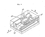
- a recording and reproducing apparatus for the optical card 50 is shown in Fig. 4.
- the optical card 50 When information is recorded on or reproduced from the optical card 50, the optical card 50 is inserted through a slot (not shown) of the apparatus of Fig. 4, and then immovably rested on a carrying means (not shown) which, as shown by a bidirectional arrow A, is moved reciprocally by a card-carrying motor 41.
- An optical head 42 is movably disposed above the moving path of the optical card 50. As shown by a bidirectional arrow B, the optical head 42 is reciprocally moved by a motor 43 in directions perpendicular to the moving direction of the card 50.
- the optical head 42 When information is recorded on or reproduced from the card 50, the optical head 42 is moved so that it is positioned above the stripe portion 63 in which information is to be recorded or from which information is to be reproduced. While changing the relative positional relation between the optical card 50 and the optical head 42, a tracking signal is obtained from the guide track 61, and the synchronizing signal from the pit train 62. The fine adjustment of the light beam of the optical head 42 is conducted on the basis of the obtained tracking signal. The recording and reproduction of information is performed in accordance with the synchronizing signal.
- the guide track 61 and the pit train 62 must be formed for each record track 63.
- the memory region 52 contains the portions 61 and 62 which are useless in the storage of information, resulting in that the prior art optical card has a reduced capacity of storing information.
- the optical card of this invention which overcomes the above-discussed and numerous other disadvantages and deficiencies of the prior art, comprises a memory region for storing information, said memory region comprises: a first section; and a second section in which information can be optically stored, said first section being juxtaposed to said second section, and a train of pits is formed in said first section.
- the memory region has a rectangular shape, and said train of pits is formed along one of the sides of said rectangular memory region.
- the pits are arranged at predetermined intervals.
- the recording and/or reproducing apparatus of this invention comprises a supporting means for supporting the above-mentioned card; an optical means; and a moving means for changing the relative positional relationship along one direction between said supporting means and said optical means, said optical means comprises a first optical head for obtaining signals from said train of pits, a second optical head for recording information on and reproducing information from said second section, and another moving means for reciprocally moving said second optical head in the direction perpendicular to said one direction.
- the optical means further comprises an adjustment means for finely adjusting the optical operation of said second optical head.
- the adjustment means adjusts the position of an object lens of said second optical head, in the direction perpendicular to said one direction and in the focusing direction.
- the adjustment means operates on the basis of the signals obtained from said first optical head.
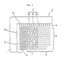
- FIG. 3 illustrates the structure of an optical card according to the invention.
- the optical card C shown in Fig. 3 comprises a plate-like plastic body 1, and a rectangular memory region 2.
- the memory region 2 has a first section 3 which elongates along one long side 2a of the memory region 2, and a second section 4 which occupies the portion of the region 2 other than the first section 3.
- a pit train 5 which consists of a plurality of circular pits 5a is formed in the first section 3.
- the pits 5a have a diameter of 2 to 5 ⁇ m and are arranged in a row at intervals of less than 10 ⁇ m.
- a plurality of tracks 8 in which information is to be stored are provided so that they extend in parallel with the pit train 5 at intervals of 2 to 5 ⁇ m.
- a long pit 6 and address pit portions 7 are formed between one short side 2b of the memory region 2 and the tracks 8.
- the long pits 6 are used for facilitating the track count control.
- Each of the address pit portions 7 indicates the address of the corresponding track 8.
- the optical card C of Fig. 3 information can be stored in the area other than those used for the pit train 5, the long pits 6 and the address pit portions 7. Namely, the optical card C of Fig. 3 comprises a large area for storing information compared to a prior art optical card.
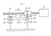
- Figure 1 illustrates a recording and reproducing apparatus for the optical card of Fig. 3.
- the apparatus of Fig. 1 has a tray 11 on which the optical card C is rested immovably.
- the tray 11 is driven by a driving means (not shown) to move the optical card C reciprocally in the directions indicated by the bidirectional arrow A.
- an optical means D which comprises a first optical head 12 and a second optical head 13.
- the first optical head 12 is fixed to a pedestal (not shown) so that pits 5a of the pit train 5 of the card C move sequentially directly under the first optical head 12.
- the second optical head 13 is movably mounted on the pedestal.
- a stepping motor 14 is provided to move the second optical head 13 along the directions indicated by the bidirectional arrow B.
- the first optical head 12 scans the pit train 5.
- the second optical head 13 is moved by the stepping motor 14 to be positioned above one of the tracks 8 into which information is to be recorded or from which information is to be reproduced, and then scans the long pit 6 and the pit portion 7 to read the address of the track 8. Thereafter, the second optical head 13 conducts the process of recording or reproduction of information.
- the operation of the optical heads 12 and 13 will be described in more detail with reference to Figs. 1 and 2.
- the second optical head 13 comprises a semiconductor laser device 21, beam splitters 22 and 23, an object lens 26, and an optical detector 28.
- the first optical head 12 comprises a beam splitter 24, an object lens 25, and an optical detector 27.
- the light beam emitted from the laser device 21 is split so that one portion of the light beam is directed to the beam splitter 24 of the first optical head 12, thereby the laser beam is impinged on the pit train 5.
- the light beam reflected from the pit train 5 enters through the splitter 24 into the detector 27 to be converted into an electric signal (control signal).
- the object lens 25 is controlled by a known control means (not shown) in the focusing direction F and the transverse direction T, thereby adequately focusing the laser spot of the optical head 12 on the pit train 5.
- the control signal is also supplied to a control means (not shown) for the second optical head 13.
- the control signal is used as a track servo signal to control the object lens 26 in the focusing direction F and the transverse direction T.
- the control signal is used also as a synchronizing signal, thereby controlling the recording and/or reproducing operation of the second optical head 13.
- the laser beam of the second optical head 13 which is controlled in accordance with the control signal scans the second section 4 of the card C.
- the light beam reflected from the second section 4 enters into the optical detector 28 through beam splitters 23 and 22, and is converted into an electric signal which will be processed to obtain information.
- the laser device 21 is mounted in the second optical head 13. Conversely, the laser device 21 may be mounted in the first optical head 12.
- the present invention can be applied to a wide variety of optical cards irrespective of the structures of the pits and the material for the memory region.
Landscapes
- Optical Recording Or Reproduction (AREA)
Applications Claiming Priority (2)
| Application Number | Priority Date | Filing Date | Title |
|---|---|---|---|
| JP63111289A JPH01282730A (ja) | 1988-05-07 | 1988-05-07 | 光学記録再生装置 |
| JP111289/88 | 1988-05-07 |
Publications (2)
| Publication Number | Publication Date |
|---|---|
| EP0341965A2 true EP0341965A2 (de) | 1989-11-15 |
| EP0341965A3 EP0341965A3 (de) | 1991-07-31 |
Family
ID=14557449
Family Applications (1)
| Application Number | Title | Priority Date | Filing Date |
|---|---|---|---|
| EP19890304649 Ceased EP0341965A3 (de) | 1988-05-07 | 1989-05-08 | Optische Karte und Aufnahme/Wiedergabegerät dafür |
Country Status (4)
| Country | Link |
|---|---|
| US (1) | US5111031A (de) |
| EP (1) | EP0341965A3 (de) |
| JP (1) | JPH01282730A (de) |
| CA (1) | CA1328692C (de) |
Cited By (1)
| Publication number | Priority date | Publication date | Assignee | Title |
|---|---|---|---|---|
| EP0874366A4 (de) * | 1996-11-11 | 2006-05-24 | Nippon Conlux Co Ltd | Datenaufzeichnungsverfahren und -gerät für optische speicherdaten |
Family Cites Families (7)
| Publication number | Priority date | Publication date | Assignee | Title |
|---|---|---|---|---|
| JPS5534340A (en) * | 1978-08-31 | 1980-03-10 | Nippon Hoso Kyokai <Nhk> | Recording reproducing system by light beam |
| JPS61216246A (ja) * | 1985-03-20 | 1986-09-25 | Hitachi Maxell Ltd | ボタン形電池の製造方法 |
| JPS6273316U (de) * | 1985-10-29 | 1987-05-11 | ||
| JPS62143231A (ja) * | 1985-12-18 | 1987-06-26 | Csk Corp | 光記録媒体 |
| US4817067A (en) * | 1986-01-27 | 1989-03-28 | Csk Corporation | Optical recording medium |
| US4918415A (en) * | 1986-05-23 | 1990-04-17 | Olympus Optical Co., Ltd. | Data reading and/or writing apparatus for use with an optical card |
| JPS63285785A (ja) * | 1987-05-19 | 1988-11-22 | Toshiba Corp | 光記録媒体とその記録再生装置 |
-
1988
- 1988-05-07 JP JP63111289A patent/JPH01282730A/ja active Pending
-
1989
- 1989-05-03 US US07/346,804 patent/US5111031A/en not_active Expired - Lifetime
- 1989-05-04 CA CA000598746A patent/CA1328692C/en not_active Expired - Fee Related
- 1989-05-08 EP EP19890304649 patent/EP0341965A3/de not_active Ceased
Cited By (1)
| Publication number | Priority date | Publication date | Assignee | Title |
|---|---|---|---|---|
| EP0874366A4 (de) * | 1996-11-11 | 2006-05-24 | Nippon Conlux Co Ltd | Datenaufzeichnungsverfahren und -gerät für optische speicherdaten |
Also Published As
| Publication number | Publication date |
|---|---|
| CA1328692C (en) | 1994-04-19 |
| EP0341965A3 (de) | 1991-07-31 |
| JPH01282730A (ja) | 1989-11-14 |
| US5111031A (en) | 1992-05-05 |
Similar Documents
| Publication | Publication Date | Title |
|---|---|---|
| EP0097035A1 (de) | System zum Aufzeichnen und Ablesen einer optischen Scheibe | |
| CA1267974A (en) | Optical information recording and reproducing apparatus | |
| US5042019A (en) | Method of and apparatus for seeking a desired track by counting track crossing signals which are detected within a predetermined time interval | |
| US5808981A (en) | Information recording/reproducing apparatus capable of movement in two directions of a card-like information recording medium | |
| US5038332A (en) | Optical information recording medium including an optically detectable mark representing a boundary between the recording and non-recording areas | |
| US5111031A (en) | Optical card and a recording/reproduction apparatus for the same | |
| JPS59104730A (ja) | 光メモリ−装置 | |
| US5136574A (en) | Optical card and a recording/reproduction apparatus for the same | |
| KR0150264B1 (ko) | 광학식 기록매체 및 기록재생시스템 | |
| EP0678860B1 (de) | Verfahren und Gerät zur optischen Aufzeichnung und Wiedergabe von Informationen | |
| US4831243A (en) | Information memory apparatus for reading out information from a moving recording medium | |
| CA1316599C (en) | Recording and reproducing device for magneto-optical card | |
| JPH04176025A (ja) | 光学ヘッド | |
| JPH0582659B2 (de) | ||
| JPH0583981B2 (de) | ||
| JP2710961B2 (ja) | 光学的情報記録再生装置 | |
| EP0383562B1 (de) | Gerät zur Aufnahme und/oder Wiedergabe von optischer Information mit Vorrichtung zum Ausschluss der optischen Kopfbewegung | |
| JP2536875B2 (ja) | 情報記録再生装置 | |
| JPS61242373A (ja) | デ−タ記録再生方法 | |
| JP2608651B2 (ja) | 光記録再生装置 | |
| JPS61283043A (ja) | 光学的情報記録再生装置 | |
| JPH0727639B2 (ja) | 光学的情報記録再生方法 | |
| JPH08338904A (ja) | 光学素子及び光学的情報記録再生装置 | |
| JPH0689481A (ja) | 光ピックアップ装置 | |
| JPS61242336A (ja) | デ−タ記録方法 |
Legal Events
| Date | Code | Title | Description |
|---|---|---|---|
| PUAI | Public reference made under article 153(3) epc to a published international application that has entered the european phase |
Free format text: ORIGINAL CODE: 0009012 |
|
| AK | Designated contracting states |
Kind code of ref document: A2 Designated state(s): DE FR GB NL |
|
| 17P | Request for examination filed |
Effective date: 19901228 |
|
| PUAL | Search report despatched |
Free format text: ORIGINAL CODE: 0009013 |
|
| AK | Designated contracting states |
Kind code of ref document: A3 Designated state(s): DE FR GB NL |
|
| 17Q | First examination report despatched |
Effective date: 19921019 |
|
| STAA | Information on the status of an ep patent application or granted ep patent |
Free format text: STATUS: THE APPLICATION HAS BEEN REFUSED |
|
| 18R | Application refused |
Effective date: 19961222 |