EP0341628A2 - Fraise, en particulier de détourage pour travailler le bois, le plastique ou similaire - Google Patents
Fraise, en particulier de détourage pour travailler le bois, le plastique ou similaire Download PDFInfo
- Publication number
- EP0341628A2 EP0341628A2 EP89108241A EP89108241A EP0341628A2 EP 0341628 A2 EP0341628 A2 EP 0341628A2 EP 89108241 A EP89108241 A EP 89108241A EP 89108241 A EP89108241 A EP 89108241A EP 0341628 A2 EP0341628 A2 EP 0341628A2
- Authority
- EP
- European Patent Office
- Prior art keywords
- milling tool
- segments
- cutting edge
- circumference
- rotation
- Prior art date
- Legal status (The legal status is an assumption and is not a legal conclusion. Google has not performed a legal analysis and makes no representation as to the accuracy of the status listed.)
- Withdrawn
Links
Images
Classifications
-
- B—PERFORMING OPERATIONS; TRANSPORTING
- B23—MACHINE TOOLS; METAL-WORKING NOT OTHERWISE PROVIDED FOR
- B23C—MILLING
- B23C5/00—Milling-cutters
- B23C5/02—Milling-cutters characterised by the shape of the cutter
- B23C5/10—Shank-type cutters, i.e. with an integral shaft
- B23C5/1081—Shank-type cutters, i.e. with an integral shaft with permanently fixed cutting inserts
-
- B—PERFORMING OPERATIONS; TRANSPORTING
- B27—WORKING OR PRESERVING WOOD OR SIMILAR MATERIAL; NAILING OR STAPLING MACHINES IN GENERAL
- B27G—ACCESSORY MACHINES OR APPARATUS FOR WORKING WOOD OR SIMILAR MATERIALS; TOOLS FOR WORKING WOOD OR SIMILAR MATERIALS; SAFETY DEVICES FOR WOOD WORKING MACHINES OR TOOLS
- B27G13/00—Cutter blocks; Other rotary cutting tools
- B27G13/002—Rotary tools without insertable or exchangeable parts, except the chucking part
Definitions
- the invention relates to a milling tool, in particular a router for machining wood, plastic and similar materials with at least one cutting edge axially divided into several sections.
- wood-based materials such as. B. chipboard, plywood, blockboard, medium density fiberboard, and of plastics and plastic composite materials, such as. B. fiber-reinforced plastics
- wood-based materials such as. B. chipboard, plywood, blockboard, medium density fiberboard, and of plastics and plastic composite materials, such as. B. fiber-reinforced plastics
- the so-called routers used here are end mills. They usually have 1 - 3 wings on the circumference, on which the sections of one or more cutting edges are attached.
- the opposing cutting edge arrangement and the interrupted cut result in individual knife blows, which expose the tool body to high alternating bending loads and generate a lot of noise.
- the abruptly pulsating cutting pressure also makes the milling spindle extraordinary heavily loaded, and there is premature bearing damage. Smaller flight circle diameters force correspondingly thin tool bodies, in which the risk of breakage is particularly great.
- the invention is therefore based on the object of creating a milling tool of the type mentioned which, with less risk of breakage, permits higher cutting capacities, protects the milling spindle bearing and generates less noise.
- the axial region of the milling cutter body carrying the cutting edge is formed by a plurality of axially adjoining, disk-shaped segments, the central longitudinal axes of which lie in an even distribution on the circumference of a common circle around the axis of rotation.
- the segments are axially adjacent in the same order in which their central longitudinal axes are adjacent on the circumference of the common circle.
- the helical arrangement of the segments with respect to the axis of rotation offers the advantage of large overs corridors or connecting surfaces between the segments. A relatively strong soul is thereby achieved and the risk of breakage is reduced.
- a cutting edge will generally be provided, the sections of which are each arranged on the circumferential region of the segments that is furthest from the axis of rotation. If the eccentricity is not too strong or the blades protrude radially from the segments, a version can also be used in which two cutting edge sections are attached diametrically opposite each other at the circumference of each segment at a distance of 90 o from the point that is the most eccentric with respect to the axis of rotation.
- the sections of the cutting edge or of the cutting edges extend axially on both sides beyond the segment carrying them.
- the cutting sections protrude axially partially from the segments in order to axially overlap one another, but since the protrusion need only be very short, there is no danger for the cutting edge.
- Cutting edges made of polycrystalline diamond are preferably used.
- the invention is also suitable for all other cutting materials used for processing plastic and wood-based materials. Accordingly, it is irrelevant to the invention how the cutting sections are attached to the tool body. The same applies to the profiles and angles on the cutting edge to be selected by the specialist in individual cases.
- the milling tool according to the invention is suitable for cutting with extreme axial angles.
- a drilling or basic cutting edge can also be attached in a conventional manner.
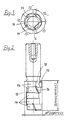
- FIG. 1 shows an end view and in FIG. 2 a side view of a router for wood or plastic processing.
- the router shown has a shaft 10 with which it is clamped in the usual manner in the tool chuck of a milling spindle.
- the router shown does not have the usual wings, but in the example is divided into five disk-shaped segments 14, each 8 mm long, arranged eccentrically to the axis of rotation 12.
- Each of the segments is essentially round, has a cutting section 16 on the circumference at the most eccentric point and is provided next to this with a recess 18 which forms a chip chamber.
- the five eccentric disc-shaped segments 14 are evenly distributed over the circumference. Their central longitudinal axes lie on a common circle with an even angular distance of 72 o . Accordingly, the points of greater eccentricity of each segment 14, where the cutting sections 16 are attached, are each 72 o apart. Regardless of whether an even or odd number of segments is selected, such segments could also be placed axially next to one another whose central longitudinal axes on the common circle are essentially diametrically opposite, but an arrangement in which those segments lie axially next to one another is preferred Central longitudinal axes are adjacent on the common circle. In this case there are large connecting or transition areas between the segments.
Landscapes
- Engineering & Computer Science (AREA)
- Mechanical Engineering (AREA)
- Life Sciences & Earth Sciences (AREA)
- Wood Science & Technology (AREA)
- Forests & Forestry (AREA)
- Milling Processes (AREA)
- Milling, Drilling, And Turning Of Wood (AREA)
Applications Claiming Priority (2)
| Application Number | Priority Date | Filing Date | Title |
|---|---|---|---|
| DE19883815917 DE3815917A1 (de) | 1988-05-10 | 1988-05-10 | Fraeswerkzeug, insbesondere oberfraeser fuer die bearbeitung von holz, kunststoff und aehnlichen materialien |
| DE3815917 | 1988-05-10 |
Publications (2)
| Publication Number | Publication Date |
|---|---|
| EP0341628A2 true EP0341628A2 (fr) | 1989-11-15 |
| EP0341628A3 EP0341628A3 (fr) | 1991-04-17 |
Family
ID=6354055
Family Applications (1)
| Application Number | Title | Priority Date | Filing Date |
|---|---|---|---|
| EP19890108241 Withdrawn EP0341628A3 (fr) | 1988-05-10 | 1989-05-08 | Fraise, en particulier de détourage pour travailler le bois, le plastique ou similaire |
Country Status (2)
| Country | Link |
|---|---|
| EP (1) | EP0341628A3 (fr) |
| DE (1) | DE3815917A1 (fr) |
Cited By (1)
| Publication number | Priority date | Publication date | Assignee | Title |
|---|---|---|---|---|
| WO2012163338A1 (fr) * | 2011-05-30 | 2012-12-06 | Leitz Gmbh & Co. Kg | Fraise à queue pour défonceuse |
Families Citing this family (2)
| Publication number | Priority date | Publication date | Assignee | Title |
|---|---|---|---|---|
| DE59301214D1 (de) * | 1993-04-05 | 1996-02-01 | Ledermann & Co | Verfahren zur Herstellung spanabhebender Werkzeuge und Werkzeug |
| CN104802319B (zh) * | 2015-05-18 | 2016-11-09 | 桂林创源金刚石有限公司 | 层叠组合式金刚石铣刀 |
Family Cites Families (4)
| Publication number | Priority date | Publication date | Assignee | Title |
|---|---|---|---|---|
| GB226727A (en) * | 1924-04-30 | 1925-01-01 | Robert Edward Maxim | Improvements in and relating to staircase housers, trenching tools, or the like for traversing operations in wood or other soft materials |
| CH254605A (de) * | 1945-11-13 | 1948-05-15 | Sortros Werkzeuge Gmbh | Fräser für Holzbearbeitung. |
| DE2438043A1 (de) * | 1974-08-07 | 1976-02-19 | Braun Kg Maschf | Entrindungsmaschine mit einem von einem antriebsmotor in umdrehung versetzten, walzenfoermigen fraeswerkzeug |
| DE8907983U1 (de) * | 1989-06-30 | 1989-10-12 | Jakob Schmid GmbH & Co., 7082 Oberkochen | Fräswerkzeuge |
-
1988
- 1988-05-10 DE DE19883815917 patent/DE3815917A1/de not_active Withdrawn
-
1989
- 1989-05-08 EP EP19890108241 patent/EP0341628A3/fr not_active Withdrawn
Cited By (1)
| Publication number | Priority date | Publication date | Assignee | Title |
|---|---|---|---|---|
| WO2012163338A1 (fr) * | 2011-05-30 | 2012-12-06 | Leitz Gmbh & Co. Kg | Fraise à queue pour défonceuse |
Also Published As
| Publication number | Publication date |
|---|---|
| DE3815917A1 (de) | 1989-11-23 |
| EP0341628A3 (fr) | 1991-04-17 |
Similar Documents
| Publication | Publication Date | Title |
|---|---|---|
| DE69306165T2 (de) | Diamantenschneiden mit geänderter Schneidkantengeometrie und ihre Montageanordnung am Bohrmeissel | |
| DE3618574C2 (de) | Positiv-wendeschneidplatte | |
| DE3347501C2 (fr) | ||
| DE102005025815A1 (de) | Schneideinsatz, insbesondere zur Kurbelwellenbearbeitung | |
| DE2850334A1 (de) | Schneckenfoerderer mit einem zwischenlager | |
| DE102014208130A1 (de) | Werkzeug zur spanenden Bearbeitung von Werkstücken | |
| DE1752127B2 (de) | Vorrichtung zur Herstellung von Granulat aus einer Kunststoff- oder Gummibahn | |
| EP3354387A1 (fr) | Outil d'enlèvement de copeaux | |
| CH637048A5 (de) | Bohrwerkzeug fuer bohrungen in metallvollmaterial von werkstuecken. | |
| DE69004868T2 (de) | Fingerfräser für die Endbearbeitung harter Werkstücke. | |
| EP3795316B1 (fr) | Tête d'outil d'un outil d'usinage | |
| EP0590408A1 (fr) | Outil pour le fraisage de mortaises et de rainures | |
| DE3815917A1 (de) | Fraeswerkzeug, insbesondere oberfraeser fuer die bearbeitung von holz, kunststoff und aehnlichen materialien | |
| DE1302331B (fr) | ||
| DE1146330B (de) | Stirnmesserkopf fuer Verzahnungsmaschinen | |
| EP3190230A1 (fr) | Coussinet pour un élément abrasif | |
| CH617612A5 (en) | Multi-piece hobbing cutter | |
| AT505113A1 (de) | Fräseinrichtung | |
| DE4443727C2 (de) | Sägemaschine mit Spiralscheiben zum Herstellen von Holzblöcken und Schneiden für solche Spiralscheiben | |
| DE8618414U1 (de) | Nutfräser | |
| DE3525514A1 (de) | Verfahren und vorrichtung zum spanabhebenden bearbeiten eines sich drehenden werkstueckes | |
| DE69835457T2 (de) | Refinerplatten für die papierherstellung und herstellungsverfahren | |
| EP0394937B1 (fr) | Couteau rotatif pour un dispositif de coupe de papier | |
| DE19832551A1 (de) | Schaftfräser mit Hartmetallschneiden | |
| DE3316380C2 (de) | Mehrschneidiger Bohrkopf |
Legal Events
| Date | Code | Title | Description |
|---|---|---|---|
| PUAI | Public reference made under article 153(3) epc to a published international application that has entered the european phase |
Free format text: ORIGINAL CODE: 0009012 |
|
| AK | Designated contracting states |
Kind code of ref document: A2 Designated state(s): AT BE CH DE ES FR GB GR IT LI LU NL SE |
|
| RBV | Designated contracting states (corrected) |
Designated state(s): DE FR GB IT SE |
|
| PUAL | Search report despatched |
Free format text: ORIGINAL CODE: 0009013 |
|
| AK | Designated contracting states |
Kind code of ref document: A3 Designated state(s): AT BE CH DE ES FR GB GR IT LI LU NL SE |
|
| STAA | Information on the status of an ep patent application or granted ep patent |
Free format text: STATUS: THE APPLICATION IS DEEMED TO BE WITHDRAWN |
|
| 18D | Application deemed to be withdrawn |
Effective date: 19911203 |