EP0341628A2 - Milling tool, in particular for a router for the working of wood, plastic or similar material - Google Patents
Milling tool, in particular for a router for the working of wood, plastic or similar material Download PDFInfo
- Publication number
- EP0341628A2 EP0341628A2 EP89108241A EP89108241A EP0341628A2 EP 0341628 A2 EP0341628 A2 EP 0341628A2 EP 89108241 A EP89108241 A EP 89108241A EP 89108241 A EP89108241 A EP 89108241A EP 0341628 A2 EP0341628 A2 EP 0341628A2
- Authority
- EP
- European Patent Office
- Prior art keywords
- milling tool
- segments
- cutting edge
- circumference
- rotation
- Prior art date
- Legal status (The legal status is an assumption and is not a legal conclusion. Google has not performed a legal analysis and makes no representation as to the accuracy of the status listed.)
- Withdrawn
Links
Images
Classifications
-
- B—PERFORMING OPERATIONS; TRANSPORTING
- B23—MACHINE TOOLS; METAL-WORKING NOT OTHERWISE PROVIDED FOR
- B23C—MILLING
- B23C5/00—Milling-cutters
- B23C5/02—Milling-cutters characterised by the shape of the cutter
- B23C5/10—Shank-type cutters, i.e. with an integral shaft
- B23C5/1081—Shank-type cutters, i.e. with an integral shaft with permanently fixed cutting inserts
-
- B—PERFORMING OPERATIONS; TRANSPORTING
- B27—WORKING OR PRESERVING WOOD OR SIMILAR MATERIAL; NAILING OR STAPLING MACHINES IN GENERAL
- B27G—ACCESSORY MACHINES OR APPARATUS FOR WORKING WOOD OR SIMILAR MATERIALS; TOOLS FOR WORKING WOOD OR SIMILAR MATERIALS; SAFETY DEVICES FOR WOOD WORKING MACHINES OR TOOLS
- B27G13/00—Cutter blocks; Other rotary cutting tools
- B27G13/002—Rotary tools without insertable or exchangeable parts, except the chucking part
Definitions
- the invention relates to a milling tool, in particular a router for machining wood, plastic and similar materials with at least one cutting edge axially divided into several sections.
- wood-based materials such as. B. chipboard, plywood, blockboard, medium density fiberboard, and of plastics and plastic composite materials, such as. B. fiber-reinforced plastics
- wood-based materials such as. B. chipboard, plywood, blockboard, medium density fiberboard, and of plastics and plastic composite materials, such as. B. fiber-reinforced plastics
- the so-called routers used here are end mills. They usually have 1 - 3 wings on the circumference, on which the sections of one or more cutting edges are attached.
- the opposing cutting edge arrangement and the interrupted cut result in individual knife blows, which expose the tool body to high alternating bending loads and generate a lot of noise.
- the abruptly pulsating cutting pressure also makes the milling spindle extraordinary heavily loaded, and there is premature bearing damage. Smaller flight circle diameters force correspondingly thin tool bodies, in which the risk of breakage is particularly great.
- the invention is therefore based on the object of creating a milling tool of the type mentioned which, with less risk of breakage, permits higher cutting capacities, protects the milling spindle bearing and generates less noise.
- the axial region of the milling cutter body carrying the cutting edge is formed by a plurality of axially adjoining, disk-shaped segments, the central longitudinal axes of which lie in an even distribution on the circumference of a common circle around the axis of rotation.
- the segments are axially adjacent in the same order in which their central longitudinal axes are adjacent on the circumference of the common circle.
- the helical arrangement of the segments with respect to the axis of rotation offers the advantage of large overs corridors or connecting surfaces between the segments. A relatively strong soul is thereby achieved and the risk of breakage is reduced.
- a cutting edge will generally be provided, the sections of which are each arranged on the circumferential region of the segments that is furthest from the axis of rotation. If the eccentricity is not too strong or the blades protrude radially from the segments, a version can also be used in which two cutting edge sections are attached diametrically opposite each other at the circumference of each segment at a distance of 90 o from the point that is the most eccentric with respect to the axis of rotation.
- the sections of the cutting edge or of the cutting edges extend axially on both sides beyond the segment carrying them.
- the cutting sections protrude axially partially from the segments in order to axially overlap one another, but since the protrusion need only be very short, there is no danger for the cutting edge.
- Cutting edges made of polycrystalline diamond are preferably used.
- the invention is also suitable for all other cutting materials used for processing plastic and wood-based materials. Accordingly, it is irrelevant to the invention how the cutting sections are attached to the tool body. The same applies to the profiles and angles on the cutting edge to be selected by the specialist in individual cases.
- the milling tool according to the invention is suitable for cutting with extreme axial angles.
- a drilling or basic cutting edge can also be attached in a conventional manner.
- FIG. 1 shows an end view and in FIG. 2 a side view of a router for wood or plastic processing.
- the router shown has a shaft 10 with which it is clamped in the usual manner in the tool chuck of a milling spindle.
- the router shown does not have the usual wings, but in the example is divided into five disk-shaped segments 14, each 8 mm long, arranged eccentrically to the axis of rotation 12.
- Each of the segments is essentially round, has a cutting section 16 on the circumference at the most eccentric point and is provided next to this with a recess 18 which forms a chip chamber.
- the five eccentric disc-shaped segments 14 are evenly distributed over the circumference. Their central longitudinal axes lie on a common circle with an even angular distance of 72 o . Accordingly, the points of greater eccentricity of each segment 14, where the cutting sections 16 are attached, are each 72 o apart. Regardless of whether an even or odd number of segments is selected, such segments could also be placed axially next to one another whose central longitudinal axes on the common circle are essentially diametrically opposite, but an arrangement in which those segments lie axially next to one another is preferred Central longitudinal axes are adjacent on the common circle. In this case there are large connecting or transition areas between the segments.
Landscapes
- Engineering & Computer Science (AREA)
- Mechanical Engineering (AREA)
- Life Sciences & Earth Sciences (AREA)
- Wood Science & Technology (AREA)
- Forests & Forestry (AREA)
- Milling Processes (AREA)
- Milling, Drilling, And Turning Of Wood (AREA)
Abstract
Es wird ein Fräswerkzeug, insbesondere ein Oberfräser, für die Bearbeitung von Holz, Kunststoff und ähnlichen Materialien vorgeschlagen. Um einen sehr stabilen, weniger als bisher zu Vibrationen neigenden Werkzeugkörper zu erhalten, ist vorgesehen, daß der die Schneide (16) tragende axiale Bereich des Fräserkörpers durch mehrere axial aneinander grenzende, scheibenförmige Segmente (14) gebildet ist, deren Mittellängsachsen in gleichmäßiger Verteilung auf dem Umfang eines gemeinsamen Kreises um die Drehachse (12) liegen. 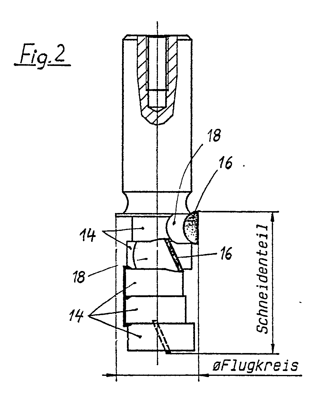
Description
Die Erfindung betrifft ein Fräswerkzeug, insbesondere einen Oberfräser für die Bearbeitung von Holz, Kunststoff und ähnlichen Materialien mit wenigstens einer axial in mehrere Abschnitte unterteilten Schneide.The invention relates to a milling tool, in particular a router for machining wood, plastic and similar materials with at least one cutting edge axially divided into several sections.
Bei der Bearbeitung von Holz, Holzwerkstoffen, wie z. B. Spanplatten, Sperrholzplatten, Tischlerplatten, mitteldichten Faserplatten, sowie von Kunststoffen und Kunststoff-Verbundmaterialien, wie z. B. faserverstärkten Kunststoffen, wird mit sehr hohen Drehzahlen von z. B. 18000 Upm oder sogar 24000 Upm des Fräswerkzeugs gearbeitet. Die dabei verwendeten sogenannten Oberfräser sind Schaftfräser. Sie haben in der Regel 1 - 3 Flügel am Umfang, an denen die Abschnitte einer oder mehrerer Schneiden angebracht sind. Durch die gegenüberliegende Schneidenanordnung und den unterbrochenen Schnitt kommt es zu einzelnen Messerschlägen, die den Werkzeugkörper einer hohen Wechselbiegebelastung aussetzen und starken Lärm erzeugen. Durch den schlagartig pulsierenden Schnittdruck wird außerdem die Frässpindel außerordentlich stark belastet, und es kommt vorzeitig zu Lagerschäden. Kleinere Flugkreisdurchmesser zwingen zu entsprechend dünnen Werkzeugkörpern, bei denen die Gefahr des Bruchs besonders groß ist.When processing wood, wood-based materials, such as. B. chipboard, plywood, blockboard, medium density fiberboard, and of plastics and plastic composite materials, such as. B. fiber-reinforced plastics, is at very high speeds of z. B. 18000 rpm or even 24000 rpm of the milling tool. The so-called routers used here are end mills. They usually have 1 - 3 wings on the circumference, on which the sections of one or more cutting edges are attached. The opposing cutting edge arrangement and the interrupted cut result in individual knife blows, which expose the tool body to high alternating bending loads and generate a lot of noise. The abruptly pulsating cutting pressure also makes the milling spindle extraordinary heavily loaded, and there is premature bearing damage. Smaller flight circle diameters force correspondingly thin tool bodies, in which the risk of breakage is particularly great.
Der Erfindung liegt daher die Aufgabe zugrunde, ein Fräswerkzeug der eingangs genannten Art zu schaffen, welches bei geringerer Bruchgefahr höhere Schnittleistungen erlaubt, die Frässpindellagerung schont und weniger Lärm erzeugt.The invention is therefore based on the object of creating a milling tool of the type mentioned which, with less risk of breakage, permits higher cutting capacities, protects the milling spindle bearing and generates less noise.
Vorstehende Aufgabe wird erfindungsgemäß dadurch gelöst, daß der die Schneide tragende axiale Bereich des Fräserkörpers durch mehrere axial aneinander grenzende, scheibenförmige Segmente gebildet ist, deren Mittellängsachsen in gleichmäßiger Verteilung auf dem Umfang eines gemeinsamen Kreises um die Drehachse liegen. Durch die Aufgliederung des Werkzeugkörpers in mehrere verhältnismäßig kleine Segmente, deren Länge z. B. nur etwa 8 mm beträgt, und durch die entsprechende Aufteilung der Schneiden wird mit zunehmender Anzahl von Segmenten auch ein zunehmend ruhigerer Lauf erreicht, weil immer mehrere Schneiden im Eingriff sind. Der Fräser kann besser ausgewuchtet werden. Es entstehen weniger Vibrationen, und dementsprechend ist auch die Lärmbelästigung geringer.The above object is achieved according to the invention in that the axial region of the milling cutter body carrying the cutting edge is formed by a plurality of axially adjoining, disk-shaped segments, the central longitudinal axes of which lie in an even distribution on the circumference of a common circle around the axis of rotation. By dividing the tool body into several relatively small segments, the length of z. B. is only about 8 mm, and due to the appropriate division of the cutting edges, an increasingly smooth running is achieved with an increasing number of segments, because there are always several cutting edges engaged. The milling cutter can be better balanced. There is less vibration and, accordingly, the noise pollution is lower.
Infolge der exzentrischen Anordnung der Segmente und damit auch der Schneiden erhält man außerdem einen sehr großen Spanraum und einen sehr freien Rücken. Hierdurch wird ein Brennen vermieden und der Schnittdruck gesenkt. Die Spanförderleistung wird erhöht.Due to the eccentric arrangement of the segments and thus the cutting, you also get a very large chip space and a very free back. This prevents burning and the cutting pressure is reduced. The chip conveying capacity is increased.
In bevorzugter Ausgestaltung der Erfindung sind die Segmente in derselben Reihenfolge axial benachbart, in welcher ihre Mittellängsachsen auf dem Umfang des gemeinsamen Kreises benachbart sind. Die mit Bezug auf die Drehachse schraubenförmige Anordnung der Segmente bietet den Vorteil großer Über gangs- bzw. Verbindungsflächen zwischen den Segmenten. Dadurch wird eine verhältnismäßig starke Seele erreicht und die Bruchgefahr gemindert.In a preferred embodiment of the invention, the segments are axially adjacent in the same order in which their central longitudinal axes are adjacent on the circumference of the common circle. The helical arrangement of the segments with respect to the axis of rotation offers the advantage of large overs corridors or connecting surfaces between the segments. A relatively strong soul is thereby achieved and the risk of breakage is reduced.
In praktischer Ausführung der Erfindung wird man in der Regel eine Schneide vorsehen, deren Abschnitte jeweils an dem am weitesten von der Drehachse entfernten Umfangsbereich der Segmente angeordnet sind. Bei nicht zu starker Exzentrizität oder weiter aus den Segmenten radial herausragenden Schneiden kann man aber auch eine Ausführung verwenden, bei welcher am Umfang jedes Segments diametral gegenüberliegend zwei Schneidenabschnitte im Abstand von 90o von dem mit Bezug auf die Drehachse am stärksten exzentrischen Punkt angebracht sind.In a practical embodiment of the invention, a cutting edge will generally be provided, the sections of which are each arranged on the circumferential region of the segments that is furthest from the axis of rotation. If the eccentricity is not too strong or the blades protrude radially from the segments, a version can also be used in which two cutting edge sections are attached diametrically opposite each other at the circumference of each segment at a distance of 90 o from the point that is the most eccentric with respect to the axis of rotation.
Um saubere bearbeitete Flächen zu erhalten, ist es bei der Erfindung zweckmäßig, daß sich die Abschnitte der Schneide bzw. der Schneiden axial jeweils beidseitig über das sie tragende Segment hinaus erstrecken. Damit ragen die Schneidenabschnitte zwar axial teilweise aus den Segmenten heraus, um sich gegenseitig axial zu überdecken, da jedoch der Überstand nur sehr kurz zu sein braucht, erwächst daraus keine Gefahr für die Schneide.In order to obtain clean machined surfaces, it is expedient in the invention that the sections of the cutting edge or of the cutting edges extend axially on both sides beyond the segment carrying them. Thus, the cutting sections protrude axially partially from the segments in order to axially overlap one another, but since the protrusion need only be very short, there is no danger for the cutting edge.
Es finden vorzugsweise Schneiden aus polykristalinem Diamant Anwendung. Die Erfindung eignet sich aber auch für alle anderen zur Bearbeitung von Kunststoff und Holzwerkstoffen zum Einsatz kommenden Schneidmaterialien. Dementsprechend ist es für die Erfindung auch unerheblich , wie die Schneidenabschnitte am Werkzeugkörper befestigt sind. Dasselbe gilt für die im Einzelfall vom Fachmann zu wählenden Profile und Winkel an der Schneide. Es sei jedoch besonders hervorgehoben, daß sich das erfindungsgemäße Fräswerkzeug für Schneiden mit extremen Achswinkeln eignet. Die Anbringung einer Bohr- bzw. Grundschneide kann ebenfalls in herkömmlicher Weise erfolgen.Cutting edges made of polycrystalline diamond are preferably used. However, the invention is also suitable for all other cutting materials used for processing plastic and wood-based materials. Accordingly, it is irrelevant to the invention how the cutting sections are attached to the tool body. The same applies to the profiles and angles on the cutting edge to be selected by the specialist in individual cases. However, it should be particularly emphasized that the milling tool according to the invention is suitable for cutting with extreme axial angles. A drilling or basic cutting edge can also be attached in a conventional manner.
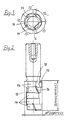
Ein Ausführungsbeispiel der Erfindung ist in der Zeichnung dargestellt. Diese zeigt in Fig. 1 eine Stirnansicht und in Fig. 2 eine Seitenansicht eines Oberfräsers für die Holz- oder Kunststoffbearbeitung.An embodiment of the invention is shown in the drawing. 1 shows an end view and in FIG. 2 a side view of a router for wood or plastic processing.
Der gezeigte Oberfräser hat einen Schaft 10, mit dem er in üblicher Weise in das Werkzeugfutter einer Frässpindel eingespannt wird. Im Schneidenteil hat der dargestellte Oberfräser jedoch nicht die sonst gebräuchlichen Flügel, sondern ist im Beispielsfall in fünf jeweils 8 mm lange, exzentrisch zur Drehachse 12 angeordnete, scheibenförmige Segmente 14 gegliedert. Jedes der Segmente ist im wesentlichen rund, trägt jeweils am Umfang an der am weitesten exzentrischen Stelle einen Schneidenabschnitt 16 und ist neben diesem mit einer Aussparung 18 versehen, die eine Spankammer bildet.The router shown has a shaft 10 with which it is clamped in the usual manner in the tool chuck of a milling spindle. In the cutting part, however, the router shown does not have the usual wings, but in the example is divided into five disk-
Wie am besten aus Fig. 1 hervorgeht, sind die fünf exzentrischen scheibenförmigen Segmente 14 gleichmäßig über den Umfang verteilt. Ihre Mittellängsachsen liegen auf einem gemeinsamen Kreis mit einem gleichmäßigen Winkelabstand von 72o. Dementsprechend liegen auch die Punkte größer Exzentrizität jedes Segments 14, wo die Schneidenabschnitte 16 angebracht sind, jeweils 72o auseinander. Man könnte zwar unabhängig davon, ob eine gerade oder ungerade Zahl von Segmenten gewählt wird, auch solche Segmente axial nebeneinander legen, deren Mittellängsachsen auf dem gemeinsamen Kreis im wesentlichen diametral gegenüberliegen, vorgezogen wird jedoch eine Anordnung, bei welcher diejenigen Segmente axial nebeneinander liegen, deren Mittellängsachsen auf dem gemeinsamen Kreis benachbart sind. In diesem Fall ergeben sich große Verbindungs- bzw. Übergangsflächen zwischen den Segmenten.As best seen in Fig. 1, the five eccentric disc-
Claims (5)
Applications Claiming Priority (2)
| Application Number | Priority Date | Filing Date | Title |
|---|---|---|---|
| DE19883815917 DE3815917A1 (en) | 1988-05-10 | 1988-05-10 | MILLING TOOL, ESPECIALLY SURFACE MILL FOR THE PROCESSING OF WOOD, PLASTIC AND SIMILAR MATERIALS |
| DE3815917 | 1988-05-10 |
Publications (2)
| Publication Number | Publication Date |
|---|---|
| EP0341628A2 true EP0341628A2 (en) | 1989-11-15 |
| EP0341628A3 EP0341628A3 (en) | 1991-04-17 |
Family
ID=6354055
Family Applications (1)
| Application Number | Title | Priority Date | Filing Date |
|---|---|---|---|
| EP19890108241 Withdrawn EP0341628A3 (en) | 1988-05-10 | 1989-05-08 | Milling tool, in particular for a router for the working of wood, plastic or similar material |
Country Status (2)
| Country | Link |
|---|---|
| EP (1) | EP0341628A3 (en) |
| DE (1) | DE3815917A1 (en) |
Cited By (1)
| Publication number | Priority date | Publication date | Assignee | Title |
|---|---|---|---|---|
| WO2012163338A1 (en) * | 2011-05-30 | 2012-12-06 | Leitz Gmbh & Co. Kg | Shank router bit |
Families Citing this family (2)
| Publication number | Priority date | Publication date | Assignee | Title |
|---|---|---|---|---|
| DE59301214D1 (en) * | 1993-04-05 | 1996-02-01 | Ledermann & Co | Process for producing cutting tools and tools |
| CN104802319B (en) * | 2015-05-18 | 2016-11-09 | 桂林创源金刚石有限公司 | Stacked combination formula diamond milling cutter |
Family Cites Families (4)
| Publication number | Priority date | Publication date | Assignee | Title |
|---|---|---|---|---|
| GB226727A (en) * | 1924-04-30 | 1925-01-01 | Robert Edward Maxim | Improvements in and relating to staircase housers, trenching tools, or the like for traversing operations in wood or other soft materials |
| CH254605A (en) * | 1945-11-13 | 1948-05-15 | Sortros Werkzeuge Gmbh | Woodworking cutter. |
| DE2438043A1 (en) * | 1974-08-07 | 1976-02-19 | Braun Kg Maschf | Motor-driven rotary roller cutter bark stripper - with blades on roller sheath for successively engaging trunk at maximum axial intervals |
| DE8907983U1 (en) * | 1989-06-30 | 1989-10-12 | Jakob Schmid GmbH & Co., 7082 Oberkochen | Milling tools |
-
1988
- 1988-05-10 DE DE19883815917 patent/DE3815917A1/en not_active Withdrawn
-
1989
- 1989-05-08 EP EP19890108241 patent/EP0341628A3/en not_active Withdrawn
Cited By (1)
| Publication number | Priority date | Publication date | Assignee | Title |
|---|---|---|---|---|
| WO2012163338A1 (en) * | 2011-05-30 | 2012-12-06 | Leitz Gmbh & Co. Kg | Shank router bit |
Also Published As
| Publication number | Publication date |
|---|---|
| DE3815917A1 (en) | 1989-11-23 |
| EP0341628A3 (en) | 1991-04-17 |
Similar Documents
| Publication | Publication Date | Title |
|---|---|---|
| DE69306165T2 (en) | Diamond cutting with changed cutting edge geometry and their mounting arrangement on the drill bit | |
| DE3618574C2 (en) | POSITIVE INSERT | |
| DE3347501C2 (en) | ||
| DE102005025815A1 (en) | Cutting insert, in particular for crankshaft machining | |
| DE2850334A1 (en) | SCREW CONVEYOR WITH AN INTERMEDIATE BEARING | |
| DE102014208130A1 (en) | Tool for machining workpieces | |
| DE1752127B2 (en) | Device for the production of granules from a plastic or rubber sheet | |
| EP3354387A1 (en) | Chipping tool | |
| CH637048A5 (en) | DRILLING TOOL FOR HOLES IN METAL FULL MATERIAL OF WORKPIECES. | |
| DE69004868T2 (en) | End mill for finishing hard workpieces. | |
| EP3795316B1 (en) | Tool head of a machining tool | |
| EP0590408A1 (en) | Tool for milling mortises and slots | |
| DE3815917A1 (en) | MILLING TOOL, ESPECIALLY SURFACE MILL FOR THE PROCESSING OF WOOD, PLASTIC AND SIMILAR MATERIALS | |
| DE1302331B (en) | ||
| DE1146330B (en) | Face cutter head for gear cutting machines | |
| EP3190230A1 (en) | Bearing bush for a grinding element | |
| CH617612A5 (en) | Multi-piece hobbing cutter | |
| AT505113A1 (en) | milling device | |
| DE4443727C2 (en) | Sawing machine with spiral disks for the production of wooden blocks and cutting for such spiral disks | |
| DE8618414U1 (en) | Groove cutter | |
| DE3525514A1 (en) | Method and device for machining a rotating workpiece | |
| DE69835457T2 (en) | REFINER PLATES FOR PAPER MANUFACTURE AND MANUFACTURING METHOD | |
| EP0394937B1 (en) | Rotating cutter for paper cutting apparatus | |
| DE19832551A1 (en) | End mill with carbide cutting edges | |
| DE3316380C2 (en) | Multi-edge drill head |
Legal Events
| Date | Code | Title | Description |
|---|---|---|---|
| PUAI | Public reference made under article 153(3) epc to a published international application that has entered the european phase |
Free format text: ORIGINAL CODE: 0009012 |
|
| AK | Designated contracting states |
Kind code of ref document: A2 Designated state(s): AT BE CH DE ES FR GB GR IT LI LU NL SE |
|
| RBV | Designated contracting states (corrected) |
Designated state(s): DE FR GB IT SE |
|
| PUAL | Search report despatched |
Free format text: ORIGINAL CODE: 0009013 |
|
| AK | Designated contracting states |
Kind code of ref document: A3 Designated state(s): AT BE CH DE ES FR GB GR IT LI LU NL SE |
|
| STAA | Information on the status of an ep patent application or granted ep patent |
Free format text: STATUS: THE APPLICATION IS DEEMED TO BE WITHDRAWN |
|
| 18D | Application deemed to be withdrawn |
Effective date: 19911203 |