EP0341518A2 - Système de balayage préobjectif - Google Patents
Système de balayage préobjectif Download PDFInfo
- Publication number
- EP0341518A2 EP0341518A2 EP89107796A EP89107796A EP0341518A2 EP 0341518 A2 EP0341518 A2 EP 0341518A2 EP 89107796 A EP89107796 A EP 89107796A EP 89107796 A EP89107796 A EP 89107796A EP 0341518 A2 EP0341518 A2 EP 0341518A2
- Authority
- EP
- European Patent Office
- Prior art keywords
- optical system
- scanning
- preobjective
- lens
- mirror
- Prior art date
- Legal status (The legal status is an assumption and is not a legal conclusion. Google has not performed a legal analysis and makes no representation as to the accuracy of the status listed.)
- Withdrawn
Links
- 230000003287 optical effect Effects 0.000 claims abstract description 77
- 230000004075 alteration Effects 0.000 claims abstract description 25
- 206010010071 Coma Diseases 0.000 claims abstract description 8
- 201000009310 astigmatism Diseases 0.000 claims abstract description 7
- 239000011521 glass Substances 0.000 description 5
- 238000000034 method Methods 0.000 description 2
- 230000009286 beneficial effect Effects 0.000 description 1
- 238000010276 construction Methods 0.000 description 1
- 238000003384 imaging method Methods 0.000 description 1
Images
Classifications
-
- G—PHYSICS
- G02—OPTICS
- G02B—OPTICAL ELEMENTS, SYSTEMS OR APPARATUS
- G02B27/00—Optical systems or apparatus not provided for by any of the groups G02B1/00 - G02B26/00, G02B30/00
- G02B27/0025—Optical systems or apparatus not provided for by any of the groups G02B1/00 - G02B26/00, G02B30/00 for optical correction, e.g. distorsion, aberration
- G02B27/0031—Optical systems or apparatus not provided for by any of the groups G02B1/00 - G02B26/00, G02B30/00 for optical correction, e.g. distorsion, aberration for scanning purposes
-
- G—PHYSICS
- G02—OPTICS
- G02B—OPTICAL ELEMENTS, SYSTEMS OR APPARATUS
- G02B26/00—Optical devices or arrangements for the control of light using movable or deformable optical elements
- G02B26/08—Optical devices or arrangements for the control of light using movable or deformable optical elements for controlling the direction of light
- G02B26/10—Scanning systems
Definitions
- the present invention relates to a preobjective scanning optical system and, in particular, to a preobjective scanning optical system for use in an apparatus for electronically reproducing photographs.
- Optical systems for imaging lasers or light emitting diodes (LEDs) onto photographic film to reproduce photographs from electronically stored signals are well known.
- Such optical systems typically use a polygon mirror scanner which is rotated at a constant angular rate to scan a spot across a film to expose it in successive lines.
- the spot speeds up as it travels further from the optic axis.
- This is unsuitable for a print system requiring equally spaced pixels written with data regularly spaced in time.
- it is unsuitable for a print requiring a constant exposure level across such a scan line.
- an optical scanning system for a printer there is a further consideration involved in designing an optical scanning system for a printer. That consideration relates to the placement of the objective lens which forms the focus of the lasers or LEDs on the film plane. These are normally classified as either preobjective or postobjective scanning systems depending on whether the polygon mirror scanner precedes or follows the spot-forming optics in the optical path. One is required to use a preobjective scanning optical system for printing on a film which is maintained in a flat plane. This is because the focus of the objective lens is on a curve if the polygon mirror scanner is disposed after the objective lens whereas the focus of the objective lens is in a flat plane if the polygon mirror scanner is disposed before the objective lens.
- the requirement of a preobjective scanning optical system presents further problems in the design of an objective lens for such a system because the objective lens forms the final spot for the entire scan angle.
- these problems arise because the objective lens of the preobjective scanning optical system is required to: (1) have a flat field; (2) be anastigmatic; and (3) cover a wide field.
- the scanning mirror of a preobjective scanning system forms the effective aperture stop for the objective lens, the lens has to be designed for a remote stop.
- the objective lens cannot be symmetric about the stop. Consequently, principles of symmetry cannot be exploited to provide a measure of aberration control.
- One approach to solving the above-identified problems in accordance with traditional design techniques found in the prior art includes designing the objective lens as an optical system comprising two parts, a collimator and an objective.
- this traditional approach presents a very difficult design problem because the objective has to be corrected for aberrations independent of the collimator. And, the control of these aberrations is more difficult in systems with a remote stop.
- a preobjective scanning optical system fabricated in accordance with the present invention is well-corrected for aberrations and can operate with a remote stop.
- the inventive preobjective scanning optical system advantageously comprises two optical systems disposed before and after, respectively, a scanning means, for example, a rotating mirror scanner.
- the first optical system for example, a lens system, does not collimate. Instead, it preferably forms a virtual image of the LEDs or lasers as the polygon mirror scanner rotates. It is slightly positive but could also be negative depending on magnification and its contribution to the state of correction of the system as a whole.
- the first optical system which, when scanned by the rotating mirror travels along a curved path, is then reimaged onto a flat, well-corrected plane by the second optical system, for example, a lens system, which is a positive optical system.
- the first optical system is a doublet which comprises a first and a second lens which correct the image for on-axis aberrations, including spherical aberrations and axial color. More specifically, the doublet comprises a first negative element followed by a positive element, and the doublet has a net power which is slightly positive.
- the second positive optical system comprises three lenses which, in combination, correct mostly for off-axis aberrations, especially astigmatism, coma, and lateral color. More specifically, the second optical system is a triplet which comprises a first negative element followed by two positive elements.
- the second optical system does not have to correct for curvature of field because the object for that lens is the virtual, curved image formed by the first optical system.
- embodiments of the present invention purposely deviate from having a collimated condition between the first and the second optical system.
- This advantageously permits the second optical system to deviate from having a flat field because, as the rotating mirror scanner rotates, it is scanning its object on a virtual curve. Further, and most advantageously, this is exactly the kind of field that is required for an optical system which is undercorrected for field curvature.
- the design of the second optical system emphasizes correction for astigmatism and other aberrations.
- the second optical system corrects for off-axis aberrations such as astigmatism and coma.
- the second optical system corrects for lateral color because there is nothing that can be done elsewhere to correct for this.
- correction of three off-axis aberrations, i.e., astigmatism, coma, and lateral color are done in the second optical system and correction of all the axial aberrations, i.e., spherical aberration and axial color are done in the first optical system.
- the design of the second optical system need only correct for a subset of the aberrations while the remaining ones are corrected by the first optical system.
- the second optical system in the preferred embodiment has distortion which is substantially the same as an f-theta distortion over relatively small scan angles.
- the pixel size focused on the film plane remains constant over the scan line so that the exposure does not change across the film.
- a further requirement for the above-described optical system is to have as much light as possible reach the film in an undistorted fashion, i.e., to make the optical system as fast as possible and, thereby, reduce the print speed as much as possible.
- This requirement is especially important when using LEDs because a typical LED does not have a very high light output.
- This requirement is satisfied by an asymmetric stop because it tolerates larger apertures in the plane perpendicular to the scan plane than apertures in the scan plane. The reason is that aberrations in the scan plane worsen more quickly with aperture in the scan plane than those which are out of the scan plane.
- the inventive optical system utilizes a stop which has an elliptical shape.
- the f-number in the scanning plane is f/7 and in the plane perpendicular to the scan plane is f/5.5. This is substantially lower than in typical laser printers available in the art which are typically much higher, for example, f/18 or higher.
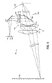
- FIG. 1 shows a plan view of a preferred embodiment of the inventive preobjective scanning optical system which is designated at 10.
- Red, green and blue LEDs 30-32 emit light which impinges upon folding mirror 40.
- Folding mirrors such as mirror 40 are not essential to the operation of the present invention but may be used, as is well known in the art, to achieve compactness.
- the light from LEDs 30-32, which is reflected from mirror 40, passes through an elliptical stop 50.
- stop 50 is made elliptical with its major axis perpendicular to the plane of the paper.
- the f-number in the plane perpendicular to the scan plane is f/5.5 whereas the f-number in the scan plane is f/7.
- optical system 60 which is comprised of a pair or lens elements 61 and 62, respectively, which comprise a doublet.
- Optical system 60 is designed to form a virtual image of LEDs 30-32 and to compensate for on-axis aberrations such as spherical aberration and axial color of the entire system 10.
- Lens 61 is negative while lens 62 is positive.
- Optical system 60 has an overall net power that is slightly positive, and is preferably itself corrected for coma over the field of the LEDs 30-32. However, it may even have negative power, depending upon magnification and its contribution to the state of correction of the overal optical system. The important property for purposes of this invention is that it not collimate.
- optical system 60 The light which passes through optical system 60 impinges upon facet 65 of a scanning mirror, the rest of the scanning mirror is not shown for simplicity.
- the scanning mirror is rotated at a substantially constant angular velocity by means (not shown) which are well-known to those of ordinary skill in the art.
- the virtual image formed by optical system 60 in conjunction with scanning mirror 65 moves in a curved path shown at 110.
- the light which is reflected from facet 65 impinges upon optical system 70 which is a triplet composed of lens elements 71, 72 and 73, respectively.
- Optical system 70 is designed to reimage the virtual image at 110, which is now its object, by focusing diverging rays from facet 65 as a spot on flat film plane 90.
- Optical system 70 is designed to correct for off-axis aberrations such as astigmatism, coma and lateral color. Still further, although optical system 60 may have a net positive or negative power, optical system 70 must have a net positive optical power. As shown in FIG. 1, lens 71 is a slightly negative element; lens 72 is a positive element; and lens 73 is a positive element, all of which are rotationally symmetric.
- optical system 70 The light which passes through optical system 70 is focused to a spot on flat film plane 90. It is well known to those of ordinary skill in the art that the spot is scanned across the film plane as facet 65 rotates about the mirror axis (not shown). Still further, it is also well known to those of ordinary skill in the art that one can move the film in a direct perpendicular to the scan direction in order to provide for exposing an entire film.
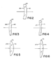
- FIGs. 2-6 show elevations of the five lenses, respectively, which comprise a preferred embodiment 10 of the inventive preobjective scanning optical system.
- FIG. 2 shows lens 61;
- FIG. 3 shows lens 62;
- FIG. 4 shows lens 71;
- FIG. 5 shows lens 72; and
- FIG. 6 shows lens 73.
- lens 61 is formed from glass having an index of refraction approximately equal to 1.5168; surfaces 161 and 261 have radii of curvature approximately equal to 2.32 in. convex and 1.518 in. concave, respectively; and the central thickness is approximately 0.15 in.
- lens 62 is formed from glass having an index of refraction approximately equal to 1.5955; surfaces 162 and 262 have radii of curvature approximately equal to infinity and 1.9198 in. convex, respectively; and the central thickness is approximately 0.15 in.
- lens 71 is formed from glass having an index of refraction approximately equal to 1.7174; surfaces 171 and 271 have radii of curvature approximately equal to 1.6048 in. concave and 11.299 in. concave, respectively; and the central thickness is approximately 0.125 in.
- lens 72 is formed from glass having an index of refraction approximately equal to 1.5168; surfaces 172 and 272 have radii of curvature approximately equal to 11.299 in. convex and 1.44 in. convex, respectively; and the central thickness is approximately 0.45 in.
- lens 73 is formed from glass having an index of refraction approximately equal to 1.5168; surfaces 173 and 273 have radii of curvature approximately equal to 8.1737 in. convex and 2.726 in. convex, respectively; and the central thickness is approximately 0.40 in.
- the elliptical stop 50 is close to surface 161 of lens 61.
Landscapes
- Physics & Mathematics (AREA)
- General Physics & Mathematics (AREA)
- Optics & Photonics (AREA)
- Mechanical Optical Scanning Systems (AREA)
- Lenses (AREA)
- Dot-Matrix Printers And Others (AREA)
- Printers Or Recording Devices Using Electromagnetic And Radiation Means (AREA)
- Exposure Or Original Feeding In Electrophotography (AREA)
Applications Claiming Priority (2)
| Application Number | Priority Date | Filing Date | Title |
|---|---|---|---|
| US191575 | 1988-05-09 | ||
| US07/191,575 US4848885A (en) | 1988-05-09 | 1988-05-09 | Preobjective scanning system |
Publications (2)
| Publication Number | Publication Date |
|---|---|
| EP0341518A2 true EP0341518A2 (fr) | 1989-11-15 |
| EP0341518A3 EP0341518A3 (fr) | 1991-07-17 |
Family
ID=22706033
Family Applications (1)
| Application Number | Title | Priority Date | Filing Date |
|---|---|---|---|
| EP19890107796 Withdrawn EP0341518A3 (fr) | 1988-05-09 | 1989-04-28 | Système de balayage préobjectif |
Country Status (5)
| Country | Link |
|---|---|
| US (1) | US4848885A (fr) |
| EP (1) | EP0341518A3 (fr) |
| JP (1) | JPH0216520A (fr) |
| CA (1) | CA1325120C (fr) |
| DE (1) | DE341518T1 (fr) |
Cited By (2)
| Publication number | Priority date | Publication date | Assignee | Title |
|---|---|---|---|---|
| EP0613035A3 (fr) * | 1993-02-26 | 1995-02-01 | Fuji Photo Film Co Ltd | Lentille f-theta. |
| EP1046939A1 (fr) * | 1999-04-22 | 2000-10-25 | Ecrm Incorporated | Méthode et appareil d' enregistrement d' une image à champ rectiligne |
Families Citing this family (8)
| Publication number | Priority date | Publication date | Assignee | Title |
|---|---|---|---|---|
| US5111325A (en) * | 1989-10-16 | 1992-05-05 | Eastman Kodak Company | F-θ lens |
| DE4032443A1 (de) * | 1990-10-12 | 1992-04-23 | Deutsche System Technik | Objektiv mit abgewinkeltem strahlengang |
| US6008834A (en) * | 1995-11-30 | 1999-12-28 | Polaroid Corporation | Bouncing ball scanner |
| US6052212A (en) * | 1998-12-14 | 2000-04-18 | Eastman Kodak Company | Method and apparatus for correcting coma in a high resolution scanner |
| RU2182717C1 (ru) * | 2001-03-16 | 2002-05-20 | Михайлов Николай Михайлович | Тепловизионный прибор |
| US7468736B2 (en) * | 2004-10-12 | 2008-12-23 | Seiko Epson Corporation | Image forming apparatus |
| CN110221420B (zh) * | 2019-06-16 | 2021-03-30 | 西安应用光学研究所 | 双视场共孔径离轴三反光学系统及设计方法 |
| NL2023384B1 (en) * | 2019-06-26 | 2021-02-01 | Confocal Nl B V | Re-scan microscope system and method |
Family Cites Families (4)
| Publication number | Priority date | Publication date | Assignee | Title |
|---|---|---|---|---|
| US4099829A (en) * | 1977-02-23 | 1978-07-11 | Harris Corporation | Flat field optical scanning system |
| US4241257A (en) * | 1979-05-24 | 1980-12-23 | Koester Charles J | Scanning microscopic apparatus |
| JPS5787540A (en) * | 1980-11-20 | 1982-06-01 | Toshiba Corp | Electronic cooking device |
| JPS58181012A (ja) * | 1982-04-19 | 1983-10-22 | Olympus Optical Co Ltd | 広視野接眼レンズ |
-
1988
- 1988-05-09 US US07/191,575 patent/US4848885A/en not_active Expired - Lifetime
-
1989
- 1989-04-05 CA CA000595789A patent/CA1325120C/fr not_active Expired - Fee Related
- 1989-04-28 EP EP19890107796 patent/EP0341518A3/fr not_active Withdrawn
- 1989-04-28 DE DE198989107796T patent/DE341518T1/de active Pending
- 1989-05-01 JP JP1112771A patent/JPH0216520A/ja active Pending
Cited By (5)
| Publication number | Priority date | Publication date | Assignee | Title |
|---|---|---|---|---|
| EP0613035A3 (fr) * | 1993-02-26 | 1995-02-01 | Fuji Photo Film Co Ltd | Lentille f-theta. |
| US5694251A (en) * | 1993-02-26 | 1997-12-02 | Fuji Photo Film Co., Ltd. | Fθ lens |
| EP0816890A3 (fr) * | 1993-02-26 | 1998-01-14 | Fuji Photo Film Co., Ltd. | Lentille f-theta |
| EP1046939A1 (fr) * | 1999-04-22 | 2000-10-25 | Ecrm Incorporated | Méthode et appareil d' enregistrement d' une image à champ rectiligne |
| US6294778B1 (en) | 1999-04-22 | 2001-09-25 | Ecrm, Inc. | Method and apparatus for recording a flat field image |
Also Published As
| Publication number | Publication date |
|---|---|
| JPH0216520A (ja) | 1990-01-19 |
| US4848885A (en) | 1989-07-18 |
| CA1325120C (fr) | 1993-12-14 |
| EP0341518A3 (fr) | 1991-07-17 |
| DE341518T1 (de) | 1990-03-01 |
Similar Documents
| Publication | Publication Date | Title |
|---|---|---|
| US5111325A (en) | F-θ lens | |
| EP1111435B1 (fr) | Système de balayage optique comportant plusieurs éléments optiques de correction des oscillations parasites réduisant les dimensions du système | |
| JP3193546B2 (ja) | 反射型走査光学系 | |
| US5550668A (en) | Multispot polygon ROS with maximized line separation depth of focus | |
| US5270851A (en) | Achromatic-type laser scanning optical system | |
| JPH06118325A (ja) | 光走査装置 | |
| JPH10197820A (ja) | 回折型色収差補正走査光学系 | |
| US4848885A (en) | Preobjective scanning system | |
| US4707085A (en) | Fθ lens for use in light beam scanner | |
| US5812181A (en) | Scanning optical apparatus | |
| US5247383A (en) | Scanner with a post facet lens system | |
| JPS585706A (ja) | 単玉▲f▼θレンズ | |
| JPH06230307A (ja) | レ−ザ走査装置及び走査レンズ | |
| JP2722269B2 (ja) | 走査光学系 | |
| US4527858A (en) | Uniform speed scanning lens having a high resolving power | |
| US5194982A (en) | Scanning optical system | |
| US5008686A (en) | Optical scanning device for scanning a predetermined surface with a plurality of light beams | |
| JPH08262323A (ja) | 走査光学系 | |
| US5146360A (en) | Light beam scanning optical system | |
| JP2576095B2 (ja) | テレセントリツクf・θレンズ | |
| JP3402875B2 (ja) | 光走査装置 | |
| JP3293662B2 (ja) | テレセントリックなfθレンズおよび光走査装置 | |
| JP2626708B2 (ja) | 走査結像光学系 | |
| JP2907292B2 (ja) | 色消しレーザ走査光学系 | |
| JPH04107517A (ja) | 光源ユニット及び該光源ユニットに用いられるレンズ |
Legal Events
| Date | Code | Title | Description |
|---|---|---|---|
| PUAI | Public reference made under article 153(3) epc to a published international application that has entered the european phase |
Free format text: ORIGINAL CODE: 0009012 |
|
| AK | Designated contracting states |
Kind code of ref document: A2 Designated state(s): DE FR GB IT NL |
|
| ITCL | It: translation for ep claims filed |
Representative=s name: RICCARDI SERGIO & CO. |
|
| TCNL | Nl: translation of patent claims filed | ||
| EL | Fr: translation of claims filed | ||
| DET | De: translation of patent claims | ||
| PUAL | Search report despatched |
Free format text: ORIGINAL CODE: 0009013 |
|
| AK | Designated contracting states |
Kind code of ref document: A3 Designated state(s): DE FR GB IT NL |
|
| 17P | Request for examination filed |
Effective date: 19911219 |
|
| 17Q | First examination report despatched |
Effective date: 19930901 |
|
| STAA | Information on the status of an ep patent application or granted ep patent |
Free format text: STATUS: THE APPLICATION IS DEEMED TO BE WITHDRAWN |
|
| 18D | Application deemed to be withdrawn |
Effective date: 19940112 |