EP0340151A2 - Broyeur - Google Patents
Broyeur Download PDFInfo
- Publication number
- EP0340151A2 EP0340151A2 EP89710033A EP89710033A EP0340151A2 EP 0340151 A2 EP0340151 A2 EP 0340151A2 EP 89710033 A EP89710033 A EP 89710033A EP 89710033 A EP89710033 A EP 89710033A EP 0340151 A2 EP0340151 A2 EP 0340151A2
- Authority
- EP
- European Patent Office
- Prior art keywords
- drum
- mill
- beater
- guide
- rotor
- Prior art date
- Legal status (The legal status is an assumption and is not a legal conclusion. Google has not performed a legal analysis and makes no representation as to the accuracy of the status listed.)
- Granted
Links
- 239000000463 material Substances 0.000 claims abstract description 38
- 238000012216 screening Methods 0.000 claims abstract description 9
- 230000001154 acute effect Effects 0.000 claims description 6
- 238000010009 beating Methods 0.000 claims description 2
- 235000013339 cereals Nutrition 0.000 description 9
- 238000000227 grinding Methods 0.000 description 9
- 238000013461 design Methods 0.000 description 4
- 238000003860 storage Methods 0.000 description 4
- 241001465754 Metazoa Species 0.000 description 3
- 230000000694 effects Effects 0.000 description 3
- 238000003801 milling Methods 0.000 description 3
- 241000251131 Sphyrna Species 0.000 description 2
- 238000004519 manufacturing process Methods 0.000 description 2
- 238000000034 method Methods 0.000 description 2
- 239000002245 particle Substances 0.000 description 2
- 235000017166 Bambusa arundinacea Nutrition 0.000 description 1
- 235000017491 Bambusa tulda Nutrition 0.000 description 1
- 241000283690 Bos taurus Species 0.000 description 1
- 235000014676 Phragmites communis Nutrition 0.000 description 1
- 244000082204 Phyllostachys viridis Species 0.000 description 1
- 235000015334 Phyllostachys viridis Nutrition 0.000 description 1
- 240000000111 Saccharum officinarum Species 0.000 description 1
- 235000007201 Saccharum officinarum Nutrition 0.000 description 1
- 244000130503 Saccharum sinense Species 0.000 description 1
- 240000008042 Zea mays Species 0.000 description 1
- 235000005824 Zea mays ssp. parviglumis Nutrition 0.000 description 1
- 235000002017 Zea mays subsp mays Nutrition 0.000 description 1
- 239000011425 bamboo Substances 0.000 description 1
- 239000004568 cement Substances 0.000 description 1
- 239000011248 coating agent Substances 0.000 description 1
- 238000000576 coating method Methods 0.000 description 1
- 238000010276 construction Methods 0.000 description 1
- 235000005822 corn Nutrition 0.000 description 1
- 238000011161 development Methods 0.000 description 1
- 238000009826 distribution Methods 0.000 description 1
- 238000005516 engineering process Methods 0.000 description 1
- 230000002349 favourable effect Effects 0.000 description 1
- 239000000835 fiber Substances 0.000 description 1
- 239000002657 fibrous material Substances 0.000 description 1
- 235000013312 flour Nutrition 0.000 description 1
- 230000005484 gravity Effects 0.000 description 1
- 239000000203 mixture Substances 0.000 description 1
- 230000002028 premature Effects 0.000 description 1
- 239000010902 straw Substances 0.000 description 1
- 238000012549 training Methods 0.000 description 1
- 238000003466 welding Methods 0.000 description 1
Images

Classifications
-
- B—PERFORMING OPERATIONS; TRANSPORTING
- B02—CRUSHING, PULVERISING, OR DISINTEGRATING; PREPARATORY TREATMENT OF GRAIN FOR MILLING
- B02C—CRUSHING, PULVERISING, OR DISINTEGRATING IN GENERAL; MILLING GRAIN
- B02C13/00—Disintegrating by mills having rotary beater elements ; Hammer mills
- B02C13/26—Details
- B02C13/282—Shape or inner surface of mill-housings
-
- B—PERFORMING OPERATIONS; TRANSPORTING
- B02—CRUSHING, PULVERISING, OR DISINTEGRATING; PREPARATORY TREATMENT OF GRAIN FOR MILLING
- B02C—CRUSHING, PULVERISING, OR DISINTEGRATING IN GENERAL; MILLING GRAIN
- B02C13/00—Disintegrating by mills having rotary beater elements ; Hammer mills
- B02C13/02—Disintegrating by mills having rotary beater elements ; Hammer mills with horizontal rotor shaft
- B02C13/04—Disintegrating by mills having rotary beater elements ; Hammer mills with horizontal rotor shaft with beaters hinged to the rotor; Hammer mills
-
- B—PERFORMING OPERATIONS; TRANSPORTING
- B02—CRUSHING, PULVERISING, OR DISINTEGRATING; PREPARATORY TREATMENT OF GRAIN FOR MILLING
- B02C—CRUSHING, PULVERISING, OR DISINTEGRATING IN GENERAL; MILLING GRAIN
- B02C13/00—Disintegrating by mills having rotary beater elements ; Hammer mills
- B02C13/26—Details
- B02C13/28—Shape or construction of beater elements
Definitions
- the invention relates to a mill, in particular a hammer mill, according to the features in the preamble of claim 1.
- Mills of this type are used, for example, to process grain into animal feed.
- a known mill of this type consists of a housing in which a sieve drum with a horizontal axis is arranged. Within this fixed sieve drum, a driven coaxial rotor is provided, to which beaters are articulated in the form of narrow plates. In operation, the free ends of the beaters run at a close distance from the drum wall, smash the regrind filled into the drum through a loading opening and press it through the sieve openings of the drum. The ground material, which is at least partially crushed in the manner of a flour, emerges from the sieve drum in accordance with the hole size and is drawn down from the interior of the housing.
- a disadvantage of this known design is that the beaters only partially smash the ground material to be ground and otherwise squeeze through the sieve drum.
- the ground material runs essentially in the wall within the sieve drum area, with the rackets moving with their free ends through this layer and possibly evading.
- This creates a high level of friction which on the one hand leads to the fact that the ground material has a high dust-like content and on the other hand a high drive power is required to overcome this friction.
- a high dust-like proportion of the ground material is undesirable since it is poorly tolerated by the animals.
- a hammer mill for crushing and separating grinding materials consisting of different materials is known, which is provided with an elongated housing having an inlet at one end, in which a hammer rotor provided on its underside is arranged which has differently designed hammers.
- This hammer mill can be used to separate crushed stems or straws, such as. B. of dried sugar cane, Chinese sugar cane, bamboo, reed, corn stalks and the like. Like. Be used to separate their fiber and market components; also for separating high-quality and other fiber materials that are mixed with cement.
- the rotor is divided into a grinding zone and then into a beating zone.
- the hammers of the grinding zone consist of a plurality of hammer groups arranged next to one another, distributed over the length of the rotor, each of which has grinding, lifting and conveying hammers, while the hammers of the impact zone have beaters which treat the coarse material passing through the impact zone gently Allow material, that is, they are designed so that they do not substantially split the coarse material, but essentially only serve to separate the already existing fine material that adheres to the coarse material.
- one type of hammers mainly serves to produce the grinding effect, another type primarily to convey and loosen the mixture which is passed through the grinding zone.
- the milling hammers are provided with convex hammer surfaces and the lifting hammers with spoon-like hammer heads, while the end faces of the hammer heads are chamfered towards the outlet end of the conveyor hammers. Furthermore, the hammers are arranged with respect to the adjacent groups so that the grinding hammers, the lifting hammers and the conveyor hammers of adjacent groups are offset in relation to one another in the circumferential direction.
- the milling hammers, lifting hammers and conveyor hammers of neighboring groups can each be arranged on a spiral in the course of the milling zone.
- the invention has for its object to design it with simple means so that the ground material, in particular grain with relatively little energy in the mill is largely broken up and not ground.
- the guide bat runs at a close distance from the drum wall and peels off the material located in the area of the drum wall, in such a way that it is directed onto the impact beater arranged behind it.
- the impact beater is designed in such a way that the material lifted from the guide beater hits the impact beater at an acute angle, is smashed there and is thrown back in the direction of the drum wall. As far as the material is then already crushed to the desired grain size, it emerges through the sieve recesses in the sieve drum. Larger grains are picked up by the next leading beater and are fed to the impact beater in the same way as described above.
- the guide plate of the guide paddle and the impact plate of the impact paddle can be varied within wide ranges, depending on the design of the mill and the material to be processed. Influencing factors here are the speed of the rotor, the radius of the screening drum, the material to be processed and the throughput.
- the guide plate with its surface facing the drum wall can have an acute angle of approximately 30 ° to the drum tangent and the baffle plate with its surface can have an acute angle of approximately 60 ° to the drum tangent (tangent in the fictitious point of contact of the racket on the drum )
- the supporting body and plate can be connected to one another, for example, by welding.
- this design permits a relatively light construction of the rackets, which means a lower load on the rotor and in particular on the bearings accommodating the rotor.
- the plates at the end of the support body Through the plates at the end of the support body, almost the entire drum width can be detected without a blower effect occurring in the remaining area of the drum, since the air can circulate freely in the area of the relatively narrow support body. This advantageously increases the relative speed between the material in the drum and the clubs, so that the material hits the disks at high speed and is broken.
- the rackets are limitedly articulated on an axis of the axes provided on the rotor, so that they can move back over a certain range in operation when they encounter obstacles such as small stones or the like. After overcoming such an obstacle, the rackets then automatically return to their intended working position due to the centrifugal force. In this way, premature wear or damage to the mill by foreign bodies can be prevented, on the one hand, effective protection against overloading of the rotor and drive is formed.
- the guide plate of the guide rack is advantageously arranged according to claim 3.
- the guide plate passing near the drum wall lifts the material in the area of the drum wall and directs it along this plate in the direction of rotation to the rear, where it then hits the impact beater, smashed and is thrown back towards the sieve drum.
- This arrangement of the guide plate enables the material to be lifted off the drum wall with low frictional resistance and largely prevents the material from being ground between the guide plate and the drum wall.
- the impact bat is expediently designed in a corresponding manner, as specified in claim 4.
- the baffle plate of the impact beater is arranged in such a way that it turns when the rotor rotates by centrifugal force in such a way that its rear edge, viewed in the direction of rotation, runs at a close distance from the drum wall.
- the material whirled up by the guide beater is broken up on this baffle plate and thrown back in the direction of the drum wall. Since the baffle plate extends close to the drum wall, the material that has not been lifted by the guide plate or that has already moved back into the area of the drum wall is also detected.
- guide or impact beaters can be arranged side by side on a rotor axis.
- preferably only one guide bat or one impact bat is articulated on each axis, which extends over the entire drum width.
- This has the advantage that the material is gripped and broken over the entire drum width.
- an embodiment according to claim 5 is advantageous.
- the air inside the drum can therefore freely circulate between the rotor and plates around the narrow supporting bodies located between them.
- a guide or baffle plate can, for example, be articulated to the associated axis on the rotor via two supporting bodies provided in the outer region.
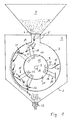
- the hammer mill shown has a housing 1 in which a cylindrical sieve drum 2 is arranged.
- the sieve drum 2 is formed by a sieve which is arranged cylindrically between the walls of the housing 1 and is laterally closed by the housing walls 3.
- the screening drum 2 is arranged at a distance from the housing walls 4 and has on its upper side a loading opening 5 which can be completely or partially shut off by a slide 6.
- the loading opening 5 is guided through the top of the housing 1 and at the same time forms the discharge opening of a storage container 7, which sits on the top of the mill housing 1.
- the housing walls 3 are penetrated approximately in the middle by a shaft 8 of a rotor 9.
- the shaft 8 is mounted in bearings 10 on the outside of the housing 1 and has a pulley 11 at one end, via which the mill can be connected to a drive unit.
- the rotor 9 has two disks 12 fixedly connected to the shaft 8, between which axles 13 are fastened near their outer circumference.
- the axes 13 are arranged parallel to the axis of rotation 14 of the shaft 8. As the section according to FIG. 1 shows, the axes 13 are all at the same radial distance from the axis of rotation 14 and are each distributed in pairs over the circumference.
- a guide beater 15 or an impact beater 16 is mounted in a limited articulated manner on each axis 13. Seen in the direction of rotation 17 of the rotor 9, the guide beater 15 and the impact beater 16 are each arranged in pairs according to the axis distribution, the guide beater 15 lying in the direction of rotation 17 lying in front of the impact beater 16.
- Each guide rack 15 consists of two support bodies 18 and a guide plate 19 attached to them.
- the support bodies 18 are rod-shaped and articulated at one end to the associated axis 13.
- the guide plate 19 connecting them is welded to the free outer end of the support body 18.
- the guide plate 19 is arranged so that it can be freely pivoted within the screening drum 2 and runs in its operating position with the front edge at a close distance from the screening drum 2.
- the guide plate 15 in the operating position shown (FIG. 1) forms an acute angle of approximately 30 ° with the tangent of the screening drum 2 at this point.
- Each impact beater 16 likewise consists of two support bodies 20 and a baffle plate 21 connecting them.
- the rod-shaped support bodies 20 are articulated at one end to the associated axis 13 and welded to the baffle plate 21 at their other end.
- the baffle plate 21 is arranged so that it runs in the operating position with its rear edge at a close distance from the wall of the screen drum.
- the baffle plate 21 forms an open angle in the direction of rotation 17 with the tangent of the screen drum 2 at this point of approximately 60 °.
- the shaft 8 of the rotor 9 is driven in the direction of rotation 17 via the pulley 11 and a drive machine (not shown) connected to it.
- the guide beater 15 and the impact beater 16 align themselves approximately radially due to the centrifugal force, as shown in FIG. 1.
- the front edges of the guide plates 19 and the rear edges of the baffle plates 21 run close to the screen drum wall.
- Gravity, centrifugal force and air whirling within the sieve drum 2 then describe the material filled into the drum 2 a path near the drum wall, as is illustrated in FIG. 1 by the arrows shown.
- the larger particles are at least partially thrown onto the sieve drum 2 by the recoil on the baffle plate 21 and likewise broken up. This process is repeated continuously by the following pairs of clubs 15, 16.
- the material is continuously fed out of the storage container 7, and the broken up grain is discharged via a discharge opening 22 on the underside of the housing 1.
Landscapes
- Engineering & Computer Science (AREA)
- Food Science & Technology (AREA)
- Crushing And Pulverization Processes (AREA)
- Combined Means For Separation Of Solids (AREA)
- Centrifugal Separators (AREA)
Priority Applications (1)
| Application Number | Priority Date | Filing Date | Title |
|---|---|---|---|
| AT89710033T ATE86144T1 (de) | 1988-04-27 | 1989-04-26 | Muehle. |
Applications Claiming Priority (2)
| Application Number | Priority Date | Filing Date | Title |
|---|---|---|---|
| DE3814191 | 1988-04-27 | ||
| DE3814191A DE3814191C1 (fr) | 1988-04-27 | 1988-04-27 |
Publications (3)
| Publication Number | Publication Date |
|---|---|
| EP0340151A2 true EP0340151A2 (fr) | 1989-11-02 |
| EP0340151A3 EP0340151A3 (en) | 1990-07-25 |
| EP0340151B1 EP0340151B1 (fr) | 1993-03-03 |
Family
ID=6352988
Family Applications (1)
| Application Number | Title | Priority Date | Filing Date |
|---|---|---|---|
| EP89710033A Expired - Lifetime EP0340151B1 (fr) | 1988-04-27 | 1989-04-26 | Broyeur |
Country Status (3)
| Country | Link |
|---|---|
| EP (1) | EP0340151B1 (fr) |
| AT (1) | ATE86144T1 (fr) |
| DE (1) | DE3814191C1 (fr) |
Cited By (1)
| Publication number | Priority date | Publication date | Assignee | Title |
|---|---|---|---|---|
| DE102007042839A1 (de) | 2007-09-10 | 2009-03-12 | Bühler AG | Schlagwerkzeug für eine Schlagmühle |
Families Citing this family (2)
| Publication number | Priority date | Publication date | Assignee | Title |
|---|---|---|---|---|
| RU2134163C1 (ru) * | 1997-06-11 | 1999-08-10 | Воронежский государственный аграрный университет им.К.Д.Глинки | Устройство для измельчения |
| RU174302U1 (ru) * | 2016-06-14 | 2017-10-11 | Федеральное государственное бюджетное образовательное Учреждение высшего образования "Воронежский государственный аграрный университет имени императора Петра 1" (ФГБОУ ВО Воронежский ГАУ) | Устройство для измельчения |
Family Cites Families (4)
| Publication number | Priority date | Publication date | Assignee | Title |
|---|---|---|---|---|
| USRE14865E (en) * | 1920-05-25 | Rotary hammer | ||
| US1871489A (en) * | 1930-05-22 | 1932-08-16 | Charles D Ammon | Combination hammer and cutter for hammer mills |
| US3011220A (en) * | 1958-05-13 | 1961-12-05 | Univ Louisiana State | Apparatus for separating mixtures of coarse and fine materials |
| AT361762B (de) * | 1979-11-23 | 1981-03-25 | Buchmann & Co | Schrotmuehle |
-
1988
- 1988-04-27 DE DE3814191A patent/DE3814191C1/de not_active Expired
-
1989
- 1989-04-26 AT AT89710033T patent/ATE86144T1/de not_active IP Right Cessation
- 1989-04-26 EP EP89710033A patent/EP0340151B1/fr not_active Expired - Lifetime
Cited By (1)
| Publication number | Priority date | Publication date | Assignee | Title |
|---|---|---|---|---|
| DE102007042839A1 (de) | 2007-09-10 | 2009-03-12 | Bühler AG | Schlagwerkzeug für eine Schlagmühle |
Also Published As
| Publication number | Publication date |
|---|---|
| ATE86144T1 (de) | 1993-03-15 |
| DE3814191C1 (fr) | 1989-08-31 |
| EP0340151A3 (en) | 1990-07-25 |
| EP0340151B1 (fr) | 1993-03-03 |
Similar Documents
| Publication | Publication Date | Title |
|---|---|---|
| WO2004024331A1 (fr) | Dispositif de broyage | |
| DE1133221B (de) | Hammermuehle | |
| EP1255612A1 (fr) | Procede et dispositif pour broyer des copeaux | |
| CH624020A5 (fr) | ||
| DE3125309C2 (de) | Zerkleinerungsvorrichtung für Abfälle | |
| DE10350123B3 (de) | Häckselvorrichtung für einen Mähdrescher | |
| EP0340151B1 (fr) | Broyeur | |
| EP1967061B1 (fr) | Hache-paille et moissonneuse équipée de celle-ci | |
| DE2620797C2 (de) | Schlägermühle zur Aufbereitung von faserhaltigen Produkten | |
| DE3230542A1 (de) | Zerkleinerungsvorrichtung | |
| AT517282B1 (de) | Mahlvorrichtung zum Mahlen von Mahlgut | |
| DE1141864B (de) | Sichtmuehle | |
| DE202021106799U1 (de) | Vorrichtung zum Fliehkraftschälen von Schälgut | |
| DE1939783C2 (fr) | ||
| DE830604C (de) | Prallmuehle, insbesondere zum Mahlen von Weizen und anderem Getreide | |
| DE2034910C3 (de) | Schlagmühle zum Vermahlen von vornehmlich feuchtem oder nassem Fruchtgut | |
| AT374377B (de) | Vorrichtung zur zerkleinerung von landwirtschaftlichem gut | |
| DE3244601C2 (de) | Mühle zum Zerkleinern von körnigen Stoffen, insbesondere von Mais, mit einer waagerechten Antriebswelle | |
| DE2554853C2 (de) | Verfahren zum Betrieb eines Siebtrommelbrechers | |
| DE3630742C2 (fr) | ||
| DE2263723C3 (de) | Schlägermühle | |
| DE1099321B (de) | Schleuderprallmuehle | |
| WO2011033416A2 (fr) | Broyeur à marteaux | |
| EP1886729B1 (fr) | Dispositif de broyage et procédé de broyage | |
| DE1221835B (de) | Einrichtung zum Aufbereiten gruener Pflanzen |
Legal Events
| Date | Code | Title | Description |
|---|---|---|---|
| PUAI | Public reference made under article 153(3) epc to a published international application that has entered the european phase |
Free format text: ORIGINAL CODE: 0009012 |
|
| AK | Designated contracting states |
Kind code of ref document: A2 Designated state(s): AT BE FR GB IT NL |
|
| PUAL | Search report despatched |
Free format text: ORIGINAL CODE: 0009013 |
|
| AK | Designated contracting states |
Kind code of ref document: A3 Designated state(s): AT BE FR GB IT NL |
|
| 17P | Request for examination filed |
Effective date: 19900619 |
|
| 17Q | First examination report despatched |
Effective date: 19911106 |
|
| GRAA | (expected) grant |
Free format text: ORIGINAL CODE: 0009210 |
|
| AK | Designated contracting states |
Kind code of ref document: B1 Designated state(s): AT BE FR GB IT NL |
|
| PG25 | Lapsed in a contracting state [announced via postgrant information from national office to epo] |
Ref country code: IT Free format text: LAPSE BECAUSE OF FAILURE TO SUBMIT A TRANSLATION OF THE DESCRIPTION OR TO PAY THE FEE WITHIN THE PRE;WARNING: LAPSES OF ITALIAN PATENTS WITH EFFECTIVE DATE BEFORE 2007 MAY HAVE OCCURRED AT ANY TIME BEFORE 2007. THE CORRECT EFFECTIVE DATE MAY BE DIFFERENT FROM THE ONE RECORDED.SCRIBED TIME-LIMIT Effective date: 19930303 Ref country code: NL Effective date: 19930303 Ref country code: BE Effective date: 19930303 Ref country code: FR Effective date: 19930303 Ref country code: GB Effective date: 19930303 |
|
| REF | Corresponds to: |
Ref document number: 86144 Country of ref document: AT Date of ref document: 19930315 Kind code of ref document: T |
|
| EN | Fr: translation not filed | ||
| NLV1 | Nl: lapsed or annulled due to failure to fulfill the requirements of art. 29p and 29m of the patents act | ||
| GBV | Gb: ep patent (uk) treated as always having been void in accordance with gb section 77(7)/1977 [no translation filed] |
Effective date: 19930303 |
|
| PLBE | No opposition filed within time limit |
Free format text: ORIGINAL CODE: 0009261 |
|
| STAA | Information on the status of an ep patent application or granted ep patent |
Free format text: STATUS: NO OPPOSITION FILED WITHIN TIME LIMIT |
|
| 26N | No opposition filed | ||
| PGFP | Annual fee paid to national office [announced via postgrant information from national office to epo] |
Ref country code: AT Payment date: 20010611 Year of fee payment: 13 |
|
| PG25 | Lapsed in a contracting state [announced via postgrant information from national office to epo] |
Ref country code: AT Free format text: LAPSE BECAUSE OF NON-PAYMENT OF DUE FEES Effective date: 20020426 |