EP0340118A1 - Stufenlose nicht umkehrbare Gelenkverbindung - Google Patents
Stufenlose nicht umkehrbare Gelenkverbindung Download PDFInfo
- Publication number
- EP0340118A1 EP0340118A1 EP89420061A EP89420061A EP0340118A1 EP 0340118 A1 EP0340118 A1 EP 0340118A1 EP 89420061 A EP89420061 A EP 89420061A EP 89420061 A EP89420061 A EP 89420061A EP 0340118 A1 EP0340118 A1 EP 0340118A1
- Authority
- EP
- European Patent Office
- Prior art keywords
- satellite
- eccentric
- flange
- movable
- common axis
- Prior art date
- Legal status (The legal status is an assumption and is not a legal conclusion. Google has not performed a legal analysis and makes no representation as to the accuracy of the status listed.)
- Granted
Links
- 230000002427 irreversible effect Effects 0.000 title claims description 12
- 230000000903 blocking effect Effects 0.000 claims description 19
- 238000006073 displacement reaction Methods 0.000 description 3
- 238000012423 maintenance Methods 0.000 description 3
- 238000010009 beating Methods 0.000 description 2
- 230000000295 complement effect Effects 0.000 description 1
- 210000004513 dentition Anatomy 0.000 description 1
- 230000000694 effects Effects 0.000 description 1
- 230000008030 elimination Effects 0.000 description 1
- 238000003379 elimination reaction Methods 0.000 description 1
- 238000005461 lubrication Methods 0.000 description 1
- 239000000463 material Substances 0.000 description 1
- 239000002184 metal Substances 0.000 description 1
- 230000003071 parasitic effect Effects 0.000 description 1
- 230000000750 progressive effect Effects 0.000 description 1
- 230000036346 tooth eruption Effects 0.000 description 1
Images

Classifications
-
- B—PERFORMING OPERATIONS; TRANSPORTING
- B60—VEHICLES IN GENERAL
- B60N—SEATS SPECIALLY ADAPTED FOR VEHICLES; VEHICLE PASSENGER ACCOMMODATION NOT OTHERWISE PROVIDED FOR
- B60N2/00—Seats specially adapted for vehicles; Arrangement or mounting of seats in vehicles
- B60N2/02—Seats specially adapted for vehicles; Arrangement or mounting of seats in vehicles the seat or part thereof being movable, e.g. adjustable
- B60N2/22—Seats specially adapted for vehicles; Arrangement or mounting of seats in vehicles the seat or part thereof being movable, e.g. adjustable the back-rest being adjustable
- B60N2/225—Seats specially adapted for vehicles; Arrangement or mounting of seats in vehicles the seat or part thereof being movable, e.g. adjustable the back-rest being adjustable by cycloidal or planetary mechanisms
- B60N2/2252—Seats specially adapted for vehicles; Arrangement or mounting of seats in vehicles the seat or part thereof being movable, e.g. adjustable the back-rest being adjustable by cycloidal or planetary mechanisms in which the central axis of the gearing lies inside the periphery of an orbital gear, e.g. one gear without sun gear
-
- B—PERFORMING OPERATIONS; TRANSPORTING
- B60—VEHICLES IN GENERAL
- B60N—SEATS SPECIALLY ADAPTED FOR VEHICLES; VEHICLE PASSENGER ACCOMMODATION NOT OTHERWISE PROVIDED FOR
- B60N2/00—Seats specially adapted for vehicles; Arrangement or mounting of seats in vehicles
- B60N2/02—Seats specially adapted for vehicles; Arrangement or mounting of seats in vehicles the seat or part thereof being movable, e.g. adjustable
-
- Y—GENERAL TAGGING OF NEW TECHNOLOGICAL DEVELOPMENTS; GENERAL TAGGING OF CROSS-SECTIONAL TECHNOLOGIES SPANNING OVER SEVERAL SECTIONS OF THE IPC; TECHNICAL SUBJECTS COVERED BY FORMER USPC CROSS-REFERENCE ART COLLECTIONS [XRACs] AND DIGESTS
- Y10—TECHNICAL SUBJECTS COVERED BY FORMER USPC
- Y10T—TECHNICAL SUBJECTS COVERED BY FORMER US CLASSIFICATION
- Y10T403/00—Joints and connections
- Y10T403/32—Articulated members
- Y10T403/32254—Lockable at fixed position
- Y10T403/32262—At selected angle
- Y10T403/32319—At selected angle including pivot stud
- Y10T403/32327—At selected angle including pivot stud including radially spaced detent or latch component
- Y10T403/32336—Engaging notch or recess in outer periphery of component
Definitions
- the invention relates to the joints used mainly for adjusting the inclination of the back of a seat relative to the seat. It applies in particular to the seats of vehicles such as, for example, those which equip motor vehicles.
- continuously adjustable joints are known, and in particular those described in patent FR 1590551.
- This document describes three particular embodiments of continuous joints comprising a satellite which cooperates by meshing with two planetary wheels.
- One of these planetary wheels is secured to the seat back by means of a suitable fitting and the other secured to the seat by means of another fitting.
- a control member drives the satellite via a shaft which rotates an eccentric and the satellite rotates the movable planetary wheel, integral with the backrest, relative to the fixed planetary wheel, integral with the seat. This adjusts the inclination of the backrest.
- the two planetary wheels are mounted on a common axis and have teeth, oriented inwards, of different diameters.
- the satellite has two teeth side by side of different diameters, oriented outwards whose dimensions are such that, under the action of the eccentric, they mesh simultaneously with the corresponding teeth of the two planetary wheels.
- this latter embodiment is all the greater the higher the ratio between the diameters of the two teeth of the satellite.
- the articulation comprises means making it possible to reduce parasitic friction such as for example ball or roller bearings which can be placed between the eccentric and the satellite or between the movable flange and a fixed annular bearing surface or even forming a bearing surface for the shaft which drives this satellite.
- parasitic friction such as for example ball or roller bearings which can be placed between the eccentric and the satellite or between the movable flange and a fixed annular bearing surface or even forming a bearing surface for the shaft which drives this satellite.
- the irreversible continuous articulation which is the subject of the invention enables the problem thus posed to be resolved as a whole. It applies not only to vehicle seats or other types of seats but can also apply to any device comprising a fixed part and a part which is movable relative to the fixed part, around a common axis.
- This articulation comprises a planetary wheel comprising connecting means which make it integral with the fixed part of the device and which is referred to as a fixed flange in the following description and in the claims. It also comprises a planetary wheel comprising connecting means which make it integral with the movable part of the device and which is referred to as a movable flange in the following description and in the claims.
- This fixed flange and this mobile flange are mounted along a common axis, an adjustment means making it possible to rotate an eccentric around this common axis so as to drive a satellite placed between the two flanges and provided with two teeth, of different diameters, arranged in two parallel planes, teeth which each cooperate with the teeth which correspond to it, integral with the fixed flange or the movable flange.
- a blocking disc centered on the common axis and locked in rotation relative to the eccentric, by means of connection means, is arranged on at least one side of the satellite in the interval between the side wall of the latter and the wall opposite the corresponding flange.
- the satellite is mounted around the eccentric with play so that a torque, exerted on the movable flange relative to the common axis, allows the side wall of the satellite, facing the blocking disc, to tilt from its plane initial of a sufficient amount to locally come into abutment against the wall opposite this disc.
- the pressure exerted locally against the wall of this blocking disc by the lateral wall of the satellite places the wall of the other face of this disc, in the corresponding zone, in abutment against the wall opposite the corresponding flange, thus causing the blocking of the disc therefore of the eccentric with respect to the corresponding flange and therefore also blocking of the movable flange with respect to the fixed flange.
- the distance which separates between them the two planes perpendicular to the axis of the satellite which each cut one of the two teeth thereof in two equal parts is at least equal to 1/35 of the average diameter of these two teeth.
- a blocking disc is arranged on each side of the satellite in each of the two intervals between each of the two side walls of this satellite and the corresponding opposite side walls of the fixed flange and the movable flange.
- At least one of the two lateral surfaces, capable of coming into abutment against one another, of the satellite and of at least one blocking disc is treated so as to increase its coefficient of friction.
- the treatment making it possible to increase the coefficient of friction of one or other of the surfaces of the satellite and of at least one blocking disc which come to bear against one another consists in: to increase the roughness of these surfaces or to project on them a rough material or with a high coefficient of friction.
- the articulation according to the invention relates to all cases where the satellite has two teeth, the diameter ratio of which is at least equal to 1.05. This diameter ratio can reach, and even exceed 2 while still allowing irreversibility thanks to the locking means according to the invention.
- this invention is more easily applicable to satellites having two outwardly facing toothing, it is also conceivable to apply it to joints comprising a satellite provided with both outwardly facing toothing and a other inward-facing toothing.
- the teeth of such a satellite cooperate with the teeth of two flanges oriented in a complementary manner. It is however necessary that the spacing of the two parallel planes perpendicular to the axis of the satellite which intersect each of the two teeth in two equal parts, is sufficient to allow the torque effect to cause the tilting of the satellite to its initial plane and its abutment against the locking disc.
- the eccentric is provided with an elastic pad allowing this play to be taken up.
- the support in rotation of the eccentric can comprise two privileged support zones which, in cooperation with the elastic pad, make it possible to suppress the beating of the mobile part of the device, the seat back in the case of FR 8616917 , due to wear.
- the addition to such an articulation of a blocking disc according to the invention makes it possible to combine the advantages of irreversibility and of taking up play.
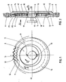
- FIG 1 and 2 a first embodiment of the device according to the invention shown schematically.
- This device comprises, in known manner an articulation for a vehicle seat comprising a fixed flange 1 connected in a known manner and not shown to the seat cushion and a mobile flange 2 connected in a manner also not shown in the seat backrest. These two flanges are articulated around a common axis X1 - X1.
- An eccentric forming a cam 3 is mounted in rotation about the same axis by a shaft 4 which rests on a bearing surface 5 provided in the movable flange 2.
- Guides or pins such as 6 ensure the maintenance of the two flanges against one another. 'other and a circular crown 7 entering a circular recess 8 ensures the centering of the two flange.
- the satellite 9 is provided with two outwardly oriented teeth 10, 11 whose ratio between the mean diameters is approximately 1.25.
- This satellite is driven by the cam forming eccentric 3 so that its teeth cooperate with the teeth oriented inwardly 12 and 13 of the fixed flange 1 and mobile 2.
- a locking disc 14 is centered on the common axis.
- connection means constituted by pins 15, 16, which penetrate into housings 17, 18, formed in eccentric 3.
- this locking disc 14 is such that it covers most of the lateral surface of the satellite 9 which is opposite the corresponding lateral surface of this disc.
- the opposite lateral surface of the same disc is opposite the corresponding lateral surface of the fixed flange 1.
- the interval between the satellite and the fixed flange 1 is just sufficient to accommodate the locking disc 14 with the clearance necessary to allow adjustment of the joint by means of the adjustment knob 19 without friction excessive.
- This pressure depends on the torque exerted on the movable flange 2 and on the distance "d" between the two planes P1 and P2, perpendicular to the common axis X1 - X1, which each intersect one of the two teeth 10, 11, of the satellite in two equal parts.
- This distance “d” is at least equal to 1/35 of the average diameter of these two teeth.
- this distance "d” is at least equal to 1/35
- FIG. 3 is a view, along arrow F2 in FIG. 2, of a particular embodiment of the device according to the invention in which a means of automatic take-up of the games is incorporated into this device, this means of automatic take-up being in itself the subject of patent application FR 861917.
- the relative arrangements of the cam 3 eccentric, of the satellite 9 and of the locking disc 14 are the same and the connection between the locking disc and the eccentric by pins and housings is unchanged.
- the fixed flange 1 is not shown.
- the upper zone of the cam eccentric has a recess 20 occupied by an elastic metal pad 21, the thinned ends 22, 23 of which are limited in displacement by the stepped parts 24, 25 of the eccentric and take support on the zones 26, 27 of this eccentric.
- the pad does not apply to the upper zone 28 of the eccentric and exerts an elastic pressure against the wall 29 of the bore of the satellite forming a bearing surface of revolution.
- the shaft 4 of the eccentric 3 has a flat 30 so as to bear on the wall 31 of the bore of the movable flange 2 of which only the area close to the axis is shown, in two preferred bearing areas. 32, 33, arranged, in the case of FIG. 3, about 120 ° from each other with respect to the common axis X1. This angle can preferably be chosen between 90 and 150 °.
- Such a particular structure ensures the stability of the joint and the take-up of wear. This results in silent operation and the elimination of the risk of file beating after a certain period of use.
- the friction of the various parts of the joint can be reduced by any known means and in particular by the use of ball or roller bearings.
- Such bearings can in particular be inserted between the cam-shaped eccentric and the satellite or between the movable flange and the fixed flange or any other fixed wall against which it bears. Thanks to the locking disc it is possible to keep the irreversibility, however.
- the irreversible continuous articulation according to the invention can be applied to any device comprising two parts: one fixed, the other movable relative to the first around a common axis, the inclination of the moving part with respect to the fixed part which must be able to be adjusted continuously and irreversibly.
Landscapes
- Engineering & Computer Science (AREA)
- Aviation & Aerospace Engineering (AREA)
- Transportation (AREA)
- Mechanical Engineering (AREA)
- Chairs For Special Purposes, Such As Reclining Chairs (AREA)
- Seats For Vehicles (AREA)
- Pivots And Pivotal Connections (AREA)
Priority Applications (1)
| Application Number | Priority Date | Filing Date | Title |
|---|---|---|---|
| AT89420061T ATE83442T1 (de) | 1988-02-23 | 1989-02-21 | Stufenlose nicht umkehrbare gelenkverbindung. |
Applications Claiming Priority (2)
| Application Number | Priority Date | Filing Date | Title |
|---|---|---|---|
| FR8802141A FR2627437B1 (fr) | 1988-02-23 | 1988-02-23 | Articulation continue irreversible pour siege |
| FR8802141 | 1988-02-23 |
Publications (2)
| Publication Number | Publication Date |
|---|---|
| EP0340118A1 true EP0340118A1 (de) | 1989-11-02 |
| EP0340118B1 EP0340118B1 (de) | 1992-12-16 |
Family
ID=9363511
Family Applications (1)
| Application Number | Title | Priority Date | Filing Date |
|---|---|---|---|
| EP89420061A Expired - Lifetime EP0340118B1 (de) | 1988-02-23 | 1989-02-21 | Stufenlose nicht umkehrbare Gelenkverbindung |
Country Status (12)
| Country | Link |
|---|---|
| US (1) | US4986602A (de) |
| EP (1) | EP0340118B1 (de) |
| JP (1) | JPH01250611A (de) |
| KR (1) | KR890012828A (de) |
| AR (1) | AR242927A1 (de) |
| AT (1) | ATE83442T1 (de) |
| BR (1) | BR8806597A (de) |
| DE (1) | DE68903871T2 (de) |
| ES (1) | ES2036363T3 (de) |
| FR (1) | FR2627437B1 (de) |
| GR (1) | GR3006683T3 (de) |
| TR (1) | TR24019A (de) |
Cited By (5)
| Publication number | Priority date | Publication date | Assignee | Title |
|---|---|---|---|---|
| DE4032603A1 (de) * | 1990-10-15 | 1992-04-16 | Keiper Recaro Gmbh Co | Gelenkbeschlag fuer sitze, insbesondere kraftfahrzeugsitze mit verstellbarer rueckenlehne |
| EP0628446A1 (de) * | 1993-06-11 | 1994-12-14 | Bertrand Faure Automobile "B.F.A." | Gelenk mit Nachregulierung des Spiels für Fahrzeugsitze |
| DE102009055022A1 (de) | 2008-12-19 | 2010-07-01 | C. Rob. Hammerstein Gmbh & Co. Kg | Lenkbetätigungseinheit für ein Kraftfahrzeug |
| DE102009055021A1 (de) | 2008-12-19 | 2010-07-22 | C. Rob. Hammerstein Gmbh & Co. Kg | Mehrfach verstellbare Lenkbestätigungseinheit für ein Kraftfahrzeug mit einem Träger und einer Lenksäule |
| DE102009055025A1 (de) | 2008-12-19 | 2010-11-18 | C. Rob. Hammerstein Gmbh & Co. Kg | Längenverstellbare Lenkbetätigungseinheit für ein Kraftfahrzeug mit einem Träger und mit einer Lenksäule |
Families Citing this family (10)
| Publication number | Priority date | Publication date | Assignee | Title |
|---|---|---|---|---|
| DE3804352A1 (de) * | 1988-02-12 | 1989-08-24 | Keiper Recaro Gmbh Co | Verstellvorrichtung fuer sitze |
| FR2659912B1 (fr) * | 1990-03-20 | 1996-04-19 | Faure Bertrand Automobile | Articulation continue sans satellite a rattrapage de jeu. |
| FR2674195B1 (fr) * | 1991-03-19 | 1993-12-17 | Faure Automobile Bertrand | Mecanisme a train hypocyclouidal pour siege de vehicule comportant un frein anti-reversible a couple differentiel. |
| DE4117497C2 (de) * | 1991-05-28 | 1997-01-16 | Johnson Controls Naue Engineer | Verstellbeschlag für Sitze mit neigungsverstellbarer Rückenlehne, insbesondere für Kraftfahrzeug-Sitze |
| US20050160938A1 (en) * | 2002-01-08 | 2005-07-28 | Samsung Electronics Co., Ltd. | Liquid inks comprising stabilizing organosols |
| DE10305407B4 (de) * | 2003-02-11 | 2006-11-02 | Keiper Gmbh & Co.Kg | Getriebebeschlag für einen Fahrzeugsitz |
| DE10315375A1 (de) * | 2003-04-03 | 2004-11-11 | Keiper Gmbh & Co. Kg | Beschlagsystem für einen Fahrzeugsitz |
| DE102006023535B4 (de) * | 2006-05-19 | 2008-12-18 | Keiper Gmbh & Co.Kg | Getriebestufe für einen Stellantrieb |
| US20080252116A1 (en) * | 2006-10-02 | 2008-10-16 | Vbpm, Limited Liability Corporation (Llc) | Therapeutic Device For Inducing Blood Pressure Modulation |
| DE202009016600U1 (de) * | 2009-12-05 | 2011-04-14 | Tk Srl. | Schwenkgelenk |
Citations (5)
| Publication number | Priority date | Publication date | Assignee | Title |
|---|---|---|---|---|
| FR1590551A (de) * | 1967-04-06 | 1970-04-20 | ||
| DE1680242B2 (de) * | 1967-07-21 | 1974-08-22 | Keiper Gmbh & Co, 7170 Schwaebisch Hall | Sicherheitseinrichtung für Sitze, insbesondere Kraftfahrzeugsitze |
| FR2467729A3 (fr) * | 1979-10-17 | 1981-04-30 | Cousin Cie Ets A & M Freres | Articulation debrayable utilisee pour des sieges de vehicules et specialement des sieges de vehicules automobiles |
| GB2073311A (en) * | 1980-04-05 | 1981-10-14 | Keiper Automobiltechnik Gmbh | Adjusting means for adjustment of the relative angular positions of two joint levers |
| FR2607761A1 (fr) * | 1986-12-03 | 1988-06-10 | Tubauto | Articulation continue pour siege de vehicule a rattrapage automatique des jeux |
Family Cites Families (7)
| Publication number | Priority date | Publication date | Assignee | Title |
|---|---|---|---|---|
| US3779655A (en) * | 1971-12-23 | 1973-12-18 | Sanshin Kinzoku Ind Co Ltd | Angle variable joint for foldable chair |
| GB1528357A (en) * | 1975-02-07 | 1978-10-11 | Ihw Eng Ltd | Seat reclining mechanism |
| DE2613195A1 (de) * | 1976-03-27 | 1977-10-06 | Schlappig Manfred Dr | Verstellbares drehgelenk |
| DE2918252A1 (de) * | 1979-05-05 | 1980-11-20 | Rentrop Hubbert & Wagner | Gelenkbeschlag fuer sitze mit verstellbarer lehne, insbesondere kraftfahrzeugsitze |
| DE3226714C2 (de) * | 1982-07-16 | 1986-09-18 | P.A. Rentrop, Hubbert & Wagner Fahrzeugausstattungen Gmbh & Co Kg, 3060 Stadthagen | Gelenkbeschlag für Kraftfahrzeugsitze mit verstellbarer Lehne |
| DE3463631D1 (en) * | 1983-03-01 | 1987-06-19 | Tubauto | Seat-back hinge for vehicles |
| US4781416A (en) * | 1986-09-11 | 1988-11-01 | Semec, Inc. | Seatback recliner |
-
1988
- 1988-02-23 FR FR8802141A patent/FR2627437B1/fr not_active Expired - Fee Related
- 1988-12-14 BR BR888806597A patent/BR8806597A/pt not_active IP Right Cessation
-
1989
- 1989-02-08 TR TR89/0123A patent/TR24019A/xx unknown
- 1989-02-14 US US07/310,358 patent/US4986602A/en not_active Expired - Fee Related
- 1989-02-20 JP JP1040130A patent/JPH01250611A/ja active Pending
- 1989-02-20 AR AR89313237A patent/AR242927A1/es active
- 1989-02-21 EP EP89420061A patent/EP0340118B1/de not_active Expired - Lifetime
- 1989-02-21 KR KR1019890002017A patent/KR890012828A/ko not_active Withdrawn
- 1989-02-21 AT AT89420061T patent/ATE83442T1/de not_active IP Right Cessation
- 1989-02-21 ES ES198989420061T patent/ES2036363T3/es not_active Expired - Lifetime
- 1989-02-21 DE DE8989420061T patent/DE68903871T2/de not_active Expired - Fee Related
-
1992
- 1992-12-24 GR GR920403146T patent/GR3006683T3/el unknown
Patent Citations (5)
| Publication number | Priority date | Publication date | Assignee | Title |
|---|---|---|---|---|
| FR1590551A (de) * | 1967-04-06 | 1970-04-20 | ||
| DE1680242B2 (de) * | 1967-07-21 | 1974-08-22 | Keiper Gmbh & Co, 7170 Schwaebisch Hall | Sicherheitseinrichtung für Sitze, insbesondere Kraftfahrzeugsitze |
| FR2467729A3 (fr) * | 1979-10-17 | 1981-04-30 | Cousin Cie Ets A & M Freres | Articulation debrayable utilisee pour des sieges de vehicules et specialement des sieges de vehicules automobiles |
| GB2073311A (en) * | 1980-04-05 | 1981-10-14 | Keiper Automobiltechnik Gmbh | Adjusting means for adjustment of the relative angular positions of two joint levers |
| FR2607761A1 (fr) * | 1986-12-03 | 1988-06-10 | Tubauto | Articulation continue pour siege de vehicule a rattrapage automatique des jeux |
Cited By (7)
| Publication number | Priority date | Publication date | Assignee | Title |
|---|---|---|---|---|
| DE4032603A1 (de) * | 1990-10-15 | 1992-04-16 | Keiper Recaro Gmbh Co | Gelenkbeschlag fuer sitze, insbesondere kraftfahrzeugsitze mit verstellbarer rueckenlehne |
| EP0628446A1 (de) * | 1993-06-11 | 1994-12-14 | Bertrand Faure Automobile "B.F.A." | Gelenk mit Nachregulierung des Spiels für Fahrzeugsitze |
| FR2706380A1 (fr) * | 1993-06-11 | 1994-12-23 | Bfa | Articulation à rattrapage de jeux utilisée dans les sièges automobiles. |
| US5536217A (en) * | 1993-06-11 | 1996-07-16 | Bertrand Faure Automobile "Bfa" | Clearance take-up articulation used in automobile seats |
| DE102009055022A1 (de) | 2008-12-19 | 2010-07-01 | C. Rob. Hammerstein Gmbh & Co. Kg | Lenkbetätigungseinheit für ein Kraftfahrzeug |
| DE102009055021A1 (de) | 2008-12-19 | 2010-07-22 | C. Rob. Hammerstein Gmbh & Co. Kg | Mehrfach verstellbare Lenkbestätigungseinheit für ein Kraftfahrzeug mit einem Träger und einer Lenksäule |
| DE102009055025A1 (de) | 2008-12-19 | 2010-11-18 | C. Rob. Hammerstein Gmbh & Co. Kg | Längenverstellbare Lenkbetätigungseinheit für ein Kraftfahrzeug mit einem Träger und mit einer Lenksäule |
Also Published As
| Publication number | Publication date |
|---|---|
| ATE83442T1 (de) | 1993-01-15 |
| KR890012828A (ko) | 1989-09-19 |
| ES2036363T3 (es) | 1993-05-16 |
| FR2627437A1 (fr) | 1989-08-25 |
| DE68903871T2 (de) | 1993-04-22 |
| DE68903871D1 (de) | 1993-01-28 |
| TR24019A (tr) | 1991-02-01 |
| FR2627437B1 (fr) | 1990-06-22 |
| JPH01250611A (ja) | 1989-10-05 |
| EP0340118B1 (de) | 1992-12-16 |
| GR3006683T3 (de) | 1993-06-30 |
| BR8806597A (pt) | 1989-05-16 |
| AR242927A1 (es) | 1993-06-30 |
| US4986602A (en) | 1991-01-22 |
Similar Documents
| Publication | Publication Date | Title |
|---|---|---|
| EP0340118B1 (de) | Stufenlose nicht umkehrbare Gelenkverbindung | |
| EP0770514B1 (de) | Gelenkbeschlag für Fahrzeugsitze | |
| EP0319393B1 (de) | Untersetzungsmechanismus mit Spielausgleich, anwendbar insbesondere zum Verstellen verschiedener Teile eines Fahrzeugsitzes | |
| EP0694434B1 (de) | Gelenkbeschlag für Fahrzeugsitz | |
| EP0628446B1 (de) | Gelenk mit Nachregulierung des Spiels für Fahrzeugsitze | |
| FR2479885A1 (fr) | Dispositif de manoeuvre pour sieges et fenetres, notamment de vehicules automobiles | |
| FR2928881A1 (fr) | Mecanisme d'articulation et siege de vehicule comportant un tel mecanisme | |
| FR2651185A1 (fr) | Mecanisme reducteur pour articulation sans jeu utilisable notamment pour le reglage de diverses parties d'un siege de vehicule automobile. | |
| FR3086595A1 (fr) | Siège de véhicule à mouvement pivotant vertical | |
| FR3100171A1 (fr) | Système de pivotement, ensemble de pivotement, siège et module de pivotement comportant le système de pivotement | |
| FR2886699A1 (fr) | Frein a tambour muni d'un dispositif de blocage | |
| FR2600603A1 (fr) | Tendeur sur un enrouleur de ceinture de securite | |
| FR2649942A1 (fr) | Ferrure d'articulation pour sieges, en particulier pour sieges de vehicules automobiles comportant un dossier reglable et susceptible de pivoter librement | |
| FR2856019A1 (fr) | Garniture d'articulation pour un dispositif de reglage d'un siege de vehicule automobile | |
| EP1556243B1 (de) | Vorrichtung zum verriegeln der konfiguration einer einrichtung,wie zum beispiel eines fahrzeugsitzes | |
| EP0188164B1 (de) | Lenkungsblock für ein Kraftfahrzeug mit festem zentralem Kissen | |
| FR2529062A1 (fr) | Armature d'articulation pour sieges a dossier reglable, notamment des sieges de vehicule automobile | |
| FR2801651A3 (fr) | Dispositif pour la reprise du jeu axial de l'arbre d'un motoreducteur | |
| WO2013190223A1 (fr) | Dispositif d'entrainement motorise pour siege de vehicule | |
| FR2770810A1 (fr) | Mecanisme d'articulation pour siege de vehicule, et siege de vehicule comportant un tel mecanisme | |
| FR2626154A1 (fr) | Procede et dispositif permettant de bloquer ou de liberer l'articulation d'un siege | |
| EP1214233B1 (de) | Feststellbremse, insbesondere für ein fahrzeug mit elektrischem antrieb | |
| EP0240416B1 (de) | Antriebsvorrichtung zum relativen Verstellen von zwei Teilen, insbesondere für Fahrzeugsitze | |
| EP1538051B1 (de) | Notbetätigungseinrichtung für eine elektromechanische Betriebsbremse | |
| EP0366563A1 (de) | Selbstsperrendes Differential |
Legal Events
| Date | Code | Title | Description |
|---|---|---|---|
| PUAI | Public reference made under article 153(3) epc to a published international application that has entered the european phase |
Free format text: ORIGINAL CODE: 0009012 |
|
| AK | Designated contracting states |
Kind code of ref document: A1 Designated state(s): AT BE CH DE ES FR GB GR IT LI LU NL SE |
|
| 17P | Request for examination filed |
Effective date: 19891108 |
|
| RAP1 | Party data changed (applicant data changed or rights of an application transferred) |
Owner name: CESA COMPAGNIE EUROPEENNE DE SIEGES POUR AUTOMOBIL |
|
| 17Q | First examination report despatched |
Effective date: 19920130 |
|
| GRAA | (expected) grant |
Free format text: ORIGINAL CODE: 0009210 |
|
| AK | Designated contracting states |
Kind code of ref document: B1 Designated state(s): AT BE CH DE ES FR GB GR IT LI LU NL SE |
|
| REF | Corresponds to: |
Ref document number: 83442 Country of ref document: AT Date of ref document: 19930115 Kind code of ref document: T |
|
| GBT | Gb: translation of ep patent filed (gb section 77(6)(a)/1977) |
Effective date: 19921216 |
|
| PGFP | Annual fee paid to national office [announced via postgrant information from national office to epo] |
Ref country code: CH Payment date: 19930120 Year of fee payment: 5 |
|
| PGFP | Annual fee paid to national office [announced via postgrant information from national office to epo] |
Ref country code: AT Payment date: 19930126 Year of fee payment: 5 |
|
| PGFP | Annual fee paid to national office [announced via postgrant information from national office to epo] |
Ref country code: GR Payment date: 19930128 Year of fee payment: 5 |
|
| REF | Corresponds to: |
Ref document number: 68903871 Country of ref document: DE Date of ref document: 19930128 |
|
| PGFP | Annual fee paid to national office [announced via postgrant information from national office to epo] |
Ref country code: LU Payment date: 19930219 Year of fee payment: 5 |
|
| ITF | It: translation for a ep patent filed | ||
| EPTA | Lu: last paid annual fee | ||
| REG | Reference to a national code |
Ref country code: ES Ref legal event code: FG2A Ref document number: 2036363 Country of ref document: ES Kind code of ref document: T3 |
|
| REG | Reference to a national code |
Ref country code: GR Ref legal event code: FG4A Free format text: 3006683 |
|
| PLBE | No opposition filed within time limit |
Free format text: ORIGINAL CODE: 0009261 |
|
| STAA | Information on the status of an ep patent application or granted ep patent |
Free format text: STATUS: NO OPPOSITION FILED WITHIN TIME LIMIT |
|
| 26N | No opposition filed | ||
| PG25 | Lapsed in a contracting state [announced via postgrant information from national office to epo] |
Ref country code: LU Free format text: LAPSE BECAUSE OF NON-PAYMENT OF DUE FEES Effective date: 19940221 Ref country code: AT Effective date: 19940221 |
|
| PG25 | Lapsed in a contracting state [announced via postgrant information from national office to epo] |
Ref country code: LI Effective date: 19940228 Ref country code: CH Effective date: 19940228 |
|
| PG25 | Lapsed in a contracting state [announced via postgrant information from national office to epo] |
Ref country code: GR Free format text: THE PATENT HAS BEEN ANNULLED BY A DECISION OF A NATIONAL AUTHORITY Effective date: 19940831 |
|
| REG | Reference to a national code |
Ref country code: CH Ref legal event code: PL |
|
| REG | Reference to a national code |
Ref country code: GR Ref legal event code: MM2A Free format text: 3006683 |
|
| EAL | Se: european patent in force in sweden |
Ref document number: 89420061.7 |
|
| PGFP | Annual fee paid to national office [announced via postgrant information from national office to epo] |
Ref country code: NL Payment date: 19970123 Year of fee payment: 9 |
|
| PGFP | Annual fee paid to national office [announced via postgrant information from national office to epo] |
Ref country code: DE Payment date: 19970124 Year of fee payment: 9 |
|
| PGFP | Annual fee paid to national office [announced via postgrant information from national office to epo] |
Ref country code: GB Payment date: 19970214 Year of fee payment: 9 |
|
| PGFP | Annual fee paid to national office [announced via postgrant information from national office to epo] |
Ref country code: ES Payment date: 19970217 Year of fee payment: 9 |
|
| PGFP | Annual fee paid to national office [announced via postgrant information from national office to epo] |
Ref country code: SE Payment date: 19970220 Year of fee payment: 9 |
|
| PGFP | Annual fee paid to national office [announced via postgrant information from national office to epo] |
Ref country code: BE Payment date: 19970317 Year of fee payment: 9 |
|
| PG25 | Lapsed in a contracting state [announced via postgrant information from national office to epo] |
Ref country code: GB Free format text: LAPSE BECAUSE OF NON-PAYMENT OF DUE FEES Effective date: 19980221 |
|
| PG25 | Lapsed in a contracting state [announced via postgrant information from national office to epo] |
Ref country code: SE Free format text: LAPSE BECAUSE OF NON-PAYMENT OF DUE FEES Effective date: 19980222 |
|
| PG25 | Lapsed in a contracting state [announced via postgrant information from national office to epo] |
Ref country code: ES Free format text: LAPSE BECAUSE OF NON-PAYMENT OF DUE FEES Effective date: 19980223 |
|
| PG25 | Lapsed in a contracting state [announced via postgrant information from national office to epo] |
Ref country code: BE Free format text: LAPSE BECAUSE OF NON-PAYMENT OF DUE FEES Effective date: 19980228 |
|
| BERE | Be: lapsed |
Owner name: CIE EUROPEENNE DE SIEGES POUR AUTOMOBILES CESA Effective date: 19980228 |
|
| PG25 | Lapsed in a contracting state [announced via postgrant information from national office to epo] |
Ref country code: NL Free format text: LAPSE BECAUSE OF NON-PAYMENT OF DUE FEES Effective date: 19980901 |
|
| GBPC | Gb: european patent ceased through non-payment of renewal fee |
Effective date: 19980221 |
|
| EUG | Se: european patent has lapsed |
Ref document number: 89420061.7 |
|
| NLV4 | Nl: lapsed or anulled due to non-payment of the annual fee |
Effective date: 19980901 |
|
| PG25 | Lapsed in a contracting state [announced via postgrant information from national office to epo] |
Ref country code: DE Free format text: LAPSE BECAUSE OF NON-PAYMENT OF DUE FEES Effective date: 19981103 |
|
| REG | Reference to a national code |
Ref country code: ES Ref legal event code: FD2A Effective date: 20000503 |
|
| PGFP | Annual fee paid to national office [announced via postgrant information from national office to epo] |
Ref country code: FR Payment date: 20040223 Year of fee payment: 16 |
|
| PG25 | Lapsed in a contracting state [announced via postgrant information from national office to epo] |
Ref country code: IT Free format text: LAPSE BECAUSE OF NON-PAYMENT OF DUE FEES;WARNING: LAPSES OF ITALIAN PATENTS WITH EFFECTIVE DATE BEFORE 2007 MAY HAVE OCCURRED AT ANY TIME BEFORE 2007. THE CORRECT EFFECTIVE DATE MAY BE DIFFERENT FROM THE ONE RECORDED. Effective date: 20050221 |
|
| PG25 | Lapsed in a contracting state [announced via postgrant information from national office to epo] |
Ref country code: FR Free format text: LAPSE BECAUSE OF NON-PAYMENT OF DUE FEES Effective date: 20051031 |
|
| REG | Reference to a national code |
Ref country code: FR Ref legal event code: ST Effective date: 20051031 |