EP0366563A1 - Selbstsperrendes Differential - Google Patents
Selbstsperrendes Differential Download PDFInfo
- Publication number
- EP0366563A1 EP0366563A1 EP89402981A EP89402981A EP0366563A1 EP 0366563 A1 EP0366563 A1 EP 0366563A1 EP 89402981 A EP89402981 A EP 89402981A EP 89402981 A EP89402981 A EP 89402981A EP 0366563 A1 EP0366563 A1 EP 0366563A1
- Authority
- EP
- European Patent Office
- Prior art keywords
- rod
- differential
- radial
- groove
- output shaft
- Prior art date
- Legal status (The legal status is an assumption and is not a legal conclusion. Google has not performed a legal analysis and makes no representation as to the accuracy of the status listed.)
- Granted
Links
Images


Classifications
-
- F—MECHANICAL ENGINEERING; LIGHTING; HEATING; WEAPONS; BLASTING
- F16—ENGINEERING ELEMENTS AND UNITS; GENERAL MEASURES FOR PRODUCING AND MAINTAINING EFFECTIVE FUNCTIONING OF MACHINES OR INSTALLATIONS; THERMAL INSULATION IN GENERAL
- F16H—GEARING
- F16H48/00—Differential gearings
- F16H48/20—Arrangements for suppressing or influencing the differential action, e.g. locking devices
- F16H48/22—Arrangements for suppressing or influencing the differential action, e.g. locking devices using friction clutches or brakes
-
- F—MECHANICAL ENGINEERING; LIGHTING; HEATING; WEAPONS; BLASTING
- F16—ENGINEERING ELEMENTS AND UNITS; GENERAL MEASURES FOR PRODUCING AND MAINTAINING EFFECTIVE FUNCTIONING OF MACHINES OR INSTALLATIONS; THERMAL INSULATION IN GENERAL
- F16H—GEARING
- F16H48/00—Differential gearings
- F16H48/06—Differential gearings with gears having orbital motion
- F16H48/08—Differential gearings with gears having orbital motion comprising bevel gears
-
- F—MECHANICAL ENGINEERING; LIGHTING; HEATING; WEAPONS; BLASTING
- F16—ENGINEERING ELEMENTS AND UNITS; GENERAL MEASURES FOR PRODUCING AND MAINTAINING EFFECTIVE FUNCTIONING OF MACHINES OR INSTALLATIONS; THERMAL INSULATION IN GENERAL
- F16H—GEARING
- F16H48/00—Differential gearings
- F16H48/06—Differential gearings with gears having orbital motion
- F16H48/10—Differential gearings with gears having orbital motion with orbital spur gears
- F16H48/11—Differential gearings with gears having orbital motion with orbital spur gears having intermeshing planet gears
-
- F—MECHANICAL ENGINEERING; LIGHTING; HEATING; WEAPONS; BLASTING
- F16—ENGINEERING ELEMENTS AND UNITS; GENERAL MEASURES FOR PRODUCING AND MAINTAINING EFFECTIVE FUNCTIONING OF MACHINES OR INSTALLATIONS; THERMAL INSULATION IN GENERAL
- F16H—GEARING
- F16H48/00—Differential gearings
- F16H48/20—Arrangements for suppressing or influencing the differential action, e.g. locking devices
- F16H48/24—Arrangements for suppressing or influencing the differential action, e.g. locking devices using positive clutches or brakes
-
- F—MECHANICAL ENGINEERING; LIGHTING; HEATING; WEAPONS; BLASTING
- F16—ENGINEERING ELEMENTS AND UNITS; GENERAL MEASURES FOR PRODUCING AND MAINTAINING EFFECTIVE FUNCTIONING OF MACHINES OR INSTALLATIONS; THERMAL INSULATION IN GENERAL
- F16H—GEARING
- F16H48/00—Differential gearings
- F16H48/06—Differential gearings with gears having orbital motion
- F16H48/08—Differential gearings with gears having orbital motion comprising bevel gears
- F16H2048/085—Differential gearings with gears having orbital motion comprising bevel gears characterised by shafts or gear carriers for orbital gears
-
- F—MECHANICAL ENGINEERING; LIGHTING; HEATING; WEAPONS; BLASTING
- F16—ENGINEERING ELEMENTS AND UNITS; GENERAL MEASURES FOR PRODUCING AND MAINTAINING EFFECTIVE FUNCTIONING OF MACHINES OR INSTALLATIONS; THERMAL INSULATION IN GENERAL
- F16H—GEARING
- F16H48/00—Differential gearings
- F16H48/38—Constructional details
- F16H48/40—Constructional details characterised by features of the rotating cases
Definitions
- the present invention relates to a self-locking differential.
- a differential has the function of driving two output shafts from the same input shaft, for example to drive the two driving wheels of a vehicle.
- the differential makes it possible to drive these two output shafts at different speeds, for example when cornering in the case of a vehicle.
- differentials include an input member, two output members, two output shafts each associated with one of the output members, and axially movable securing means for securing by their axial displacement two of the three input members and Release.
- This axial displacement can moreover be limited to the adjustment of the clearances, the essential operating parameter not being the displacement itself but the force applied to the securing means.
- the present invention aims to overcome this drawback.
- the subject of the invention is a self-locking differential, comprising an inlet member, two outlet members, two outlet shafts each associated with one of the outlet members, and axially movable fastening means for fastening by their axial displacement two of the three input and output members, characterized in that it comprises locking means, to oppose said axial movement of the securing means as long as the resistive torque on this output shaft retains a sufficient value.
- the blocking means can be arranged between at least the one of the planetary gears and the output shaft associated with it.
- the blocking means consist of the pinions themselves, which, by their toothing reaction, oppose the securing means, each planetary pinion can then be produced in one piece with the associated output tree.
- said blocking means may comprise at least a first radial rod engaged in a first radial groove with a V cross section, the first radial rod being driven in rotation by one of the elements constituted by the planetary pinion and by the output shaft and the first radial rod being formed in a member driven in rotation by the other of these elements, the resistive torque being transmitted from the output shaft to the planetary pinion by the bearing force of said first radial rod on one of the sides of said first groove and the relative axial movement of the first rod and of the first radial groove opposing the axial movement of the securing means.
- the axis of the rod being parallel to the edge of the V, the two sides of the latter form ramps so that, as long as the output torque transmitted from the sun gear to the output shaft retains a sufficient value, the rod tends to climb on these ramps.
- the resulting relative axial movement is used to oppose the axial movement of the securing means, and therefore to block the latter means.
- the rod then resumes its place in the groove thus allowing the securing means to move axially and therefore to join the two desired bodies among the three input and output bodies.
- the rod does not necessarily constitute an independent member of the element in which it is mounted. It may for example consist of a simple rib of semi-circular or V-shaped section formed on a surface of this element.
- the sides of the V-groove may not be symmetrical and possibly not be planar, for example with a view to obtaining progressiveness in the connection.
- the first radial rod can also be engaged in two first radial grooves, the openings of which face each other, one of these grooves being formed in a member integral in rotation with the planetary pinion and the other groove being formed in a member integral in rotation of the output shaft.
- the rod then has the effect of tending to separate the two groove-carrying members axially, by pressing on the opposite sides of the two grooves.
- the securing means comprise a clutch with two sets of interposed discs, the discs of one set being fixed in rotation with one of the members to be joined and the discs of the other set being fixed in rotation of the other member to be joined, said axial displacement causing friction of one of the sets of discs on the other.
- the securing means may comprise a dog clutch assembly comprising, for example, the ends facing the shafts of the planetary gears, one of the shafts being fluted internally and the other shaft being fluted externally .
- the differential according to the invention may include elastic means tending to bring the securing means into the axial securing position, the blocking means acting against these elastic means.
- It may also include a second radial rod engaged in a second radial groove, this second radial rod being integral in rotation with one of the elements constituted by the input member and by the means of joining, and the second radial groove being formed in the other of these elements, the axial displacement being caused by the bearing force of the second rod on one of the sides of the second groove.
- the same phenomenon as described above with respect to the resistive torque occurs at the input torque.
- the latter tends to cause the second rod to rise on one of the ramps formed by the second V-shaped groove and consequently to cause relative axial displacement between the input member and the securing means.
- the input torque can be transmitted from the differential housing, or from an input shaft, to the input member via the second rod.
- the securing means can act by an axial displacement of the input member under the action of thrust means acting during a decrease in one of the output torques.
- the locking means can then comprise at least a third radial rod engaged in a third radial groove with a V-section, the third rod being integral in rotation with one of the elements constituted by the output shaft corresponding to one of the outlet members and by this outlet member itself, and the third groove being formed in the other of these elements, the corresponding resistive torque being applied to the outlet member by means of the pressing force exerted by the third rod on one of the sides of the third groove.
- the resistive torque causes the third rod to rise on one of the ramps formed by the third V-groove, hence a relative axial displacement between the support member of the third rod and the element in which the third groove, this axial movement being used to block the thrust means. If this resistive torque decreases, the third rod resumes its place in the third groove thus allowing an unlocking of the thrust means, and consequently a joining of the two desired members among the three input and output members.
- the axial direction of opening of the third groove must be such that the support forces of the third rod on the third groove oppose the thrust means.
- the third radial rod can be mounted integral in rotation with the output shaft corresponding to the planetary pinion and the third radial groove can be formed in said planetary pinion.
- the input member comprises the crown of the planetary gear and the second output member comprises the planet carrier of the planetary gear, at least a fourth rod being mounted integral in rotation with the planet carrier, and engaged in a V-shaped radial groove formed in a member integral with the output shaft corresponding to the planet carrier, the resistive torque being transmitted from said output shaft to the planet carrier via said fourth rod.
- said fourth rod can be mounted in a back-pressure member integral in rotation with the planet carrier, said fastening means being mounted between the crown and said back-pressure member.
- the planetary pinion and said member integral with the output shaft can be mounted in abutment against one another and arranged so as to slide axially with respect to the differential housing.
- the input member comprises the planet carrier of the planetary gear and the second output member comprises the crown of the planetary gear, at least a fifth radial rod being mounted integral in rotation of the output shaft corresponding to the crown, and engaged in a fifth radial groove with a V section formed in the crown, the resistive torque being transmitted from said output shaft to the crown via said fifth rod.
- said crown can be mounted axially fixed relative to the differential housing, said securing means being arranged between said crown and the sun gear.
- the fifth rod can more particularly be mounted in a member integral with said output shaft, this member and the planetary pinion being in abutment against one another, and arranged in a sliding manner with respect to the differential housing.
- These precharge means can act, as the case may be, either in the same direction as the thrust means, or in the opposite direction.
- This cam may have a substantially triangular section, one of its vertices being engaged in the groove and its opposite base being engaged in the recess.
- the member in which the groove is formed, and the member in which is formed the recess include stops to limit their relative angular sliding.
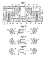
- These two differentials with bevel gears comprise in a known manner a housing 1 a , 1 b secured to an input bevel gear 2 b (not shown in FIG. 1), a planet carrier 3 a , 3 b secured in rotation to the box 1 a , 1 b and supporting the axes 4a, 4b of the satellites 5 a , 5 b , two output shafts 6 a , 6 b and 7 a , 7 b respectively, and two planetary gears 8 a , 8 b and 9 a , 9 b respectively, meshing with satellites 5 a , 5 b .
- the output shafts 6 a and 7 a terminate inside the housing 1 a by plates 10 and 11 respectively, bearing on the flanges of the housing, these plates each supporting at their periphery a set of axial extensions 12 and 13 These extensions carry radial rods 14, 15.
- Each radial rod is engaged in a radial groove 16, 17 formed respectively in radial projections 18, 19 of fluted shafts 20, 21 coaxial with the output shafts 6 a and 7 a .
- the shafts 20 and 21 carry, in their axially external zone, external grooves on which pinions 8 a and 9 a are engaged respectively.
- the splined shaft 20 also carries outer splines 22 while the shaft 21 carries at its radially inner end inner splines 23 capable of receiving the splines 22 of the shaft 20.
- two Belleville washers 24 and 25 are arranged between the inner faces of the plates 10 and 11 and the axially outer ends of the shafts 20 and 21, in order to press these two shafts towards one another so as to tend to engage the grooves 22 in the grooves 23.
- the grooves 16 and 17 have their openings which face towards the plane of symmetry of the differential.
- the input torque applied to the housing 1 a is transmitted to the shafts 20 and 21 via the planet carrier 3 a , planet gears 5 a , and planetary gears 8 a , 9 a .
- Figure 2c shows the differential in its normal operation.
- the resistant torques on the output shafts 6 a and 7 a produce a relative sliding in rotation of the rods 14 and 15 along the ramps formed by the grooves 16 and 17 respectively, this sliding in rotation causing a separation shafts 20 and 21 against the action of the washers 24 and 25.
- FIG. 2 a represents the symmetrical case in which the resistive torque applied to the output shaft 7 a decreases, which allows a displacement to the left of the shaft 21 and a locking under the same conditions of the differential.
- connection is made between the two outputs.
- the locking of a differential can also be obtained by securing the input and an output. This could be obtained in the present case by replacing the grooves 22 and 23 of the shafts 20 and 21 by dogs formed at the axially inner ends of the extensions 18 and 19, on either side of the grooves 16 and 17, and arranged for s '' engage in corresponding recesses formed in the planet carrier 3.
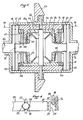
- the planet carrier 3 b is rotated from the housing 1 b by means of radial rods 26, integral with the ends of the planet carrier axes 4b and interposed with drive fingers 27 integral with the housing 1b .
- the rods 26 are also engaged in radial grooves 28 with a V cross section formed in two pressure members 29 and 30 disposed between the housing 1b and the planet carrier 3b .
- the grooves 28 are open face to face and therefore enclose the finger 26.
- Each axis 31, 32 of the planetary gears, integral with this pinion, is grooved externally and drives in rotation by these grooves a plate 33 forming radial grooves 34 open axially outwardly facing radial grooves 35 formed in a plate 36 integral in rotation with one of the output shafts 6b and 7b .
- Radial rods 37 are engaged between the plates 33 and 36 in the facing grooves 34 and 35.
- each axis 31 and 32 also receive a first set of friction discs 38 interposed with a second set of friction discs 39 mounted in notches of the planet carrier 3b .
- the discs 38 are thus integral in rotation of the planetary gears 8 b and 9 b, while discs 39 are in rotation with the planet carrier 3 b.
- the discs 38 and 39 are locked axially, on the one hand towards the plane of symmetry by a plate 40 secured to one of the pressure members 29, 30, and on the other side on the opposite side by a circlip 41 secured axially to the door -satellites 3 b .
- Belleville washers 42 are mounted between the planet carrier 3b and the plates 40 so as to tend to spread the pressure members 29 and 30 axially outwards, so as to exert a prestress on the discs 38 and 39.
- needle stops 43 and 44 are arranged between the lateral flanges of the housing 1b and the plates 36 and, respectively, between the plates 33 and the pressure members 29 and 30.
- FIG. 4 illustrates the normal operation of this differential.
- the pressure members 30 are therefore pushed towards the plane of symmetry of the differential, the rods 26 therefore being unable to mount the ramps formed by the sides of the grooves 28.
- the rods 37 will tend to descend to the bottom of the grooves 34 and 35, then allowing an axial displacement towards the outside of the pressure members 30. This axial displacement will caused on the one hand by the prestress applied by the Belleville washers 42, and on the other hand, by the bearing force of the rods 26 on the rear flank of the corresponding groove 28.
- the embodiment shown in the drawings has the advantage of allowing asymmetry between the pressure members 29 and 30, the rod 26 being able to remain at the bottom of the groove 28 corresponding to one of these members while mounting the along one of the sides of the groove of the other member.
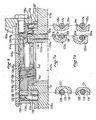
- These two differentials with planetary gear trains comprise, in a known manner, a housing 101a, 101b secured to an input conical pinion 102a (not shown in FIG. 8), a crown 103a, 103b, a planet carrier 104a, 104b, a pinion planetary 105a, 105b and two output shafts 106a, 106b and 107a, 107b respectively.
- Figures 5 and 6 corresponds to a differential where the torque input is through the crown, and where the first output is made by the planet carrier and the second output by the sun gear.
- the planet carrier 104a supports a certain number of pairs of satellites 108, 108 ′ meshing with each other, the satellites 108 having teeth 109 for meshing with teeth 110 of the planetary pinion and the satellites 108 ′ having teeth 111 to mesh with teeth 112 from the crown.
- FIGS. 8 and 9 represent a differential, therefore the torque input is effected by the planet carrier 104b, and where the first output is effected by the crown 103b and the second output by the planet gear 105b.
- the planet carrier 104b supports a set of satellites 113 provided with teeth 114 to mesh simultaneously with teeth 115 of the planetary pinion and teeth 116 of the crown.
- rods 117a, 117b are mounted radially in the housing 101a, 101b, fixed relative thereto.
- a second set of radial rods 120a, 120b is mounted in one end 121a, 121b of the output shaft 107a, 107b, fixed relative to this shaft.
- the rods 120a, 120b are engaged in radial grooves 122a, 122b with a V section, formed in an end portion 123a, 123b of the planetary gear 105a, 105b.
- the pressure member 119a is integral with the crown 103a.
- a back-pressure member 125 is integral in rotation with the planet carrier 104a by means of grooves 126 allowing relative axial displacement of these two parts.
- two sets of friction discs 127 and 128 are arranged between the planet carrier 104a and the back-pressure member 125.
- the discs 127 are integral in rotation with the planetary pinion 105a and the discs 128 are integral in rotation with the assembly constituted by the crown 103a and the back-pressure member 125, these two sets of discs being interposed.
- the back-pressure member 125 also carries radial rods 129 engaged in radial grooves 130 of V-section formed in the ends 131 of the output shaft 106a.
- a needle bearing 132 is disposed between the back-pressure member 125 and a Belleville washer 133 held axially outward by a cover 134 fixed to the housing 101a by a circlip 135.
- a needle bearing 136 is disposed between an annular shoulder 137 of the pressure member 119a and the radial rods 120a.
- the radial grooves 118a and 122a are open axially on the same side, to the right of the figures, the groove 130 being open on the other side.
- part of the torque is firstly transmitted to the planet carrier 104a and then, via the grooves 126, to the back-pressure member. 125 and to the rods 129 which, being engaged in the grooves 130, transmit this torque to the output shaft 106a.
- the other part of the input torque is transmitted, via the satellites 108, 108 ′, to the planetary pinion 105a which, by means of its grooves 122a transmits this other part of the torque to the rods 120a and therefore to the output shaft 107a.
- Figure 7a shows the differential in normal operation.
- the resistant torques on the axes 106a and 107a produce a sliding of the rods 129 and 120a along the ramps formed by the grooves 130 and 122a respectively. Stops 138 and 139 respectively formed following the ramps limit this sliding.
- the rods 129 descend the ramps of the grooves 130 to find themselves at the bottom of these grooves as shown in FIG. 7b.
- the shaft 106a, the planetary pinion 105a and the output shaft 107a can thus move to the left of FIG. 5, thus allowing the input torque applied to the rods 117a to cause these rods to rise along the ramps of the grooves 118a by moving the pressure member 119a to the left.
- stops 139 have the effect of canceling the axial force exerted by the rods 120a on the planetary pinion 105a, a force which, if not, could become greater than the force exerted at the inlet and therefore preventing the operation described above.
- a preload can also be applied by the Belleville washer 133 as well as possibly by another Belleville washer 141 disposed between the stack of discs 127, 128 and the planet carrier 104a.
- connection is made between the two outputs. It is known, however, that the locking of a differential can also be obtained by securing the input and an output.
- the pressure member 119b is made integral in rotation with the planet carrier 104b by means of fingers 142, cooperating with splines 143 of this planet carrier.
- Two sets of friction discs 144 and 145 are arranged between a stop disc 146 and a Belleville washer 147.
- the Belleville washer 147 bears against the planet carrier 104b and the stop disc 146 is held on the crown 103b by a retaining ring 148.
- Radial rods 149 are fixedly mounted in the end 150 of the shaft 106b and are engaged in radial grooves 151 with a V section of the crown 103b.
- This crown 103b is held axially fixed relative to the housing 101b on the one hand by a shoulder 152 of this housing and on the other hand, by a needle stop 153 bearing on a cover 154 fixed to the housing by a circlip 155.
- the pressure member 119b also forms a shoulder 156 which is in abutment on the end 123b of the planetary pinion 105b by means of another needle bearing 157.
- the grooves 118b, 122b and 151 are all open axially on the same side of the differential, namely, on the right side of FIG. 8.
- This member 119b then transmits the input torque to the planet carrier 104b via the pins 142.
- the input torque is also applied via the satellites 113 to the planetary pinion 105b and, via the grooves 122b, to the rods 120b and to the output shaft 107b.
- the pressure member 119b being in abutment against the planet carrier 104b, the latter also moves to the left, compressing, by means of the Belleville washer 147, the clutch discs 144 and 145.
- the output shafts 106b and 107b are thus secured by means of the rods 149, the crown 103b, the disks 144 and 145, the planetary gear 105b, and the rods 120b.
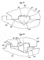
- Figures 11 and 12 show an alternative to the rod systems described above in which there is a member secured to a rod engaged in a rib formed in another member, one of these members being motor and the other member being driven, the reaction of the rod on the sides of the rib causing an axial force used to ensure the operation of the device.
- the rod which was integral with a member 200 is replaced by a cam 201 of substantially triangular shape, in this particular isosceles case, the base 202 of which is engaged in a recess 203 of the member 200, and the vertex 204 opposite the base 202 is engaged at the bottom of the groove 205 of the member opposite 206.
- the assembly will adopt the configuration of FIG. 12 in which the cam 201 has tilted, in the measure where the resistive torque applied to the member 206 is sufficient.
- Two cooperating stops 207 and 208 can be provided on the members 200 and 206 respectively to limit the relative sliding of these members.
Landscapes
- Engineering & Computer Science (AREA)
- General Engineering & Computer Science (AREA)
- Mechanical Engineering (AREA)
- Retarders (AREA)
Priority Applications (1)
| Application Number | Priority Date | Filing Date | Title |
|---|---|---|---|
| AT89402981T ATE100182T1 (de) | 1988-10-28 | 1989-10-27 | Selbstsperrendes differential. |
Applications Claiming Priority (8)
| Application Number | Priority Date | Filing Date | Title |
|---|---|---|---|
| FR8814158A FR2638500B1 (fr) | 1988-10-28 | 1988-10-28 | Differentiel autobloquant a train epicycloidal |
| FR8814158 | 1988-10-28 | ||
| FR8816392A FR2640341B1 (fr) | 1988-12-13 | 1988-12-13 | Differentiel autobloquant a pignons coniques |
| FR8816392 | 1988-12-13 | ||
| FR8902351 | 1989-02-23 | ||
| FR8902351A FR2643435A2 (fr) | 1988-10-28 | 1989-02-23 | Differentiel autobloquant a train epicycloidal |
| FR8902350A FR2643434A2 (fr) | 1988-12-13 | 1989-02-23 | Differentiel autobloquant a pignons coniques |
| FR8902350 | 1989-02-23 |
Publications (2)
| Publication Number | Publication Date |
|---|---|
| EP0366563A1 true EP0366563A1 (de) | 1990-05-02 |
| EP0366563B1 EP0366563B1 (de) | 1994-01-12 |
Family
ID=27446648
Family Applications (1)
| Application Number | Title | Priority Date | Filing Date |
|---|---|---|---|
| EP89402981A Expired - Lifetime EP0366563B1 (de) | 1988-10-28 | 1989-10-27 | Selbstsperrendes Differential |
Country Status (4)
| Country | Link |
|---|---|
| EP (1) | EP0366563B1 (de) |
| JP (1) | JPH02245546A (de) |
| DE (1) | DE68912269T2 (de) |
| ES (1) | ES2048857T3 (de) |
Cited By (4)
| Publication number | Priority date | Publication date | Assignee | Title |
|---|---|---|---|---|
| EP0441331A1 (de) * | 1990-02-05 | 1991-08-14 | Klöckner-Humboldt-Deutz Aktiengesellschaft | Selbstsperrendes Ausgleichsgetriebe |
| EP0733832A1 (de) * | 1995-03-20 | 1996-09-25 | Lajous Industries S.A. | Automatisches Sperrdifferential |
| FR2741686A1 (fr) * | 1995-11-24 | 1997-05-30 | Renault | Differentiel auto-freine |
| WO2013001195A1 (fr) * | 2011-06-30 | 2013-01-03 | Renault S.A.S. | Différentiel autobloquant a angles de rampe optimises |
Families Citing this family (2)
| Publication number | Priority date | Publication date | Assignee | Title |
|---|---|---|---|---|
| JP2008224020A (ja) * | 2007-03-15 | 2008-09-25 | Obata Fukuji | 三輪車の差動装置 |
| DE102021207659B4 (de) | 2021-07-19 | 2023-02-02 | Zf Friedrichshafen Ag | Stirnraddifferential mit passiver Sperrfunktion sowie Antriebsstrang und Kraftfahrzeug mit einem solchen Differential |
Citations (9)
| Publication number | Priority date | Publication date | Assignee | Title |
|---|---|---|---|---|
| DE888808C (de) * | 1944-04-27 | 1953-09-03 | E H Carl F W Borgward Dr Ing | Selbstsperrendes Ausgleichgetriebe |
| DE926469C (de) * | 1952-06-29 | 1955-04-18 | Zettelmeyer Fa Hubert | Selbsttaetige Sperrvorrichtung fuer Ausgleichgetriebe, insbesondere von Kraftfahrzeugen |
| US2855805A (en) * | 1957-09-30 | 1958-10-14 | Gleason Works | Differential mechanism |
| US3055234A (en) * | 1959-05-28 | 1962-09-25 | Dana Corp | Locking differential |
| FR1441293A (fr) * | 1965-07-28 | 1966-06-03 | Rockwell Standard Co | Différentiel à action différentielle limitée |
| FR1572402A (de) * | 1967-04-26 | 1969-06-27 | ||
| FR2380158A1 (fr) * | 1977-02-12 | 1978-09-08 | Daimler Benz Ag | Differentiel a blocage automatique pour vehicules, en particulier differentiel a pignons coniques |
| FR2547883A1 (fr) * | 1983-06-27 | 1984-12-28 | Bossuet Claude | Dispositif de perfectionnement pour differentiel |
| FR2604504A1 (fr) * | 1986-09-26 | 1988-04-01 | Poncet Pierre | Differentiel a effet auto-bloquant pour transmissions de vehicules et applications analogues |
Family Cites Families (1)
| Publication number | Priority date | Publication date | Assignee | Title |
|---|---|---|---|---|
| FR1596579A (de) * | 1967-09-28 | 1970-06-22 |
-
1989
- 1989-10-27 EP EP89402981A patent/EP0366563B1/de not_active Expired - Lifetime
- 1989-10-27 ES ES89402981T patent/ES2048857T3/es not_active Expired - Lifetime
- 1989-10-27 DE DE1989612269 patent/DE68912269T2/de not_active Expired - Fee Related
- 1989-10-30 JP JP28283289A patent/JPH02245546A/ja active Pending
Patent Citations (9)
| Publication number | Priority date | Publication date | Assignee | Title |
|---|---|---|---|---|
| DE888808C (de) * | 1944-04-27 | 1953-09-03 | E H Carl F W Borgward Dr Ing | Selbstsperrendes Ausgleichgetriebe |
| DE926469C (de) * | 1952-06-29 | 1955-04-18 | Zettelmeyer Fa Hubert | Selbsttaetige Sperrvorrichtung fuer Ausgleichgetriebe, insbesondere von Kraftfahrzeugen |
| US2855805A (en) * | 1957-09-30 | 1958-10-14 | Gleason Works | Differential mechanism |
| US3055234A (en) * | 1959-05-28 | 1962-09-25 | Dana Corp | Locking differential |
| FR1441293A (fr) * | 1965-07-28 | 1966-06-03 | Rockwell Standard Co | Différentiel à action différentielle limitée |
| FR1572402A (de) * | 1967-04-26 | 1969-06-27 | ||
| FR2380158A1 (fr) * | 1977-02-12 | 1978-09-08 | Daimler Benz Ag | Differentiel a blocage automatique pour vehicules, en particulier differentiel a pignons coniques |
| FR2547883A1 (fr) * | 1983-06-27 | 1984-12-28 | Bossuet Claude | Dispositif de perfectionnement pour differentiel |
| FR2604504A1 (fr) * | 1986-09-26 | 1988-04-01 | Poncet Pierre | Differentiel a effet auto-bloquant pour transmissions de vehicules et applications analogues |
Cited By (6)
| Publication number | Priority date | Publication date | Assignee | Title |
|---|---|---|---|---|
| EP0441331A1 (de) * | 1990-02-05 | 1991-08-14 | Klöckner-Humboldt-Deutz Aktiengesellschaft | Selbstsperrendes Ausgleichsgetriebe |
| EP0733832A1 (de) * | 1995-03-20 | 1996-09-25 | Lajous Industries S.A. | Automatisches Sperrdifferential |
| FR2732087A1 (fr) * | 1995-03-20 | 1996-09-27 | Lajous Ind Sa | Perfectionnements aux differentiels autobloquants |
| FR2741686A1 (fr) * | 1995-11-24 | 1997-05-30 | Renault | Differentiel auto-freine |
| WO2013001195A1 (fr) * | 2011-06-30 | 2013-01-03 | Renault S.A.S. | Différentiel autobloquant a angles de rampe optimises |
| FR2977289A1 (fr) * | 2011-06-30 | 2013-01-04 | Renault Sa | Differentiel autobloquant a angles de rampe optimises |
Also Published As
| Publication number | Publication date |
|---|---|
| JPH02245546A (ja) | 1990-10-01 |
| DE68912269T2 (de) | 1994-07-14 |
| EP0366563B1 (de) | 1994-01-12 |
| DE68912269D1 (de) | 1994-02-24 |
| ES2048857T3 (es) | 1994-04-01 |
Similar Documents
| Publication | Publication Date | Title |
|---|---|---|
| EP0415820B1 (de) | Untersetzungsmechanismus für ein Gelenk mit Spielausgleich, anwendbar insbesondere zum Verstellen verschiedener Teile eines Fahrzeugsitzes | |
| FR2610381A1 (fr) | Ensemble formant differentiel a glissement limite | |
| EP2501960B1 (de) | Sperrdifferenzial mit dynamischer schubvorrichtung | |
| FR2462620A1 (fr) | Differentiel pour vehicule a moteur | |
| FR2807488A1 (fr) | Dispositif de commande axiale | |
| FR2606477A1 (fr) | Dispositif d'embrayage a rattrapage d'usure automatique | |
| FR2672949A1 (fr) | Dispositif de transmission de mouvement de rotation. | |
| WO2002099313A1 (fr) | Dispositif de verrouillage des pignons de transmission | |
| FR2525717A1 (fr) | Differentiel autobloquant | |
| FR2540583A1 (fr) | Systeme d'amortissement a disque | |
| FR3006637A1 (fr) | Mecanisme d'articulation et siege de vehicule comportant un tel mecanisme | |
| FR2546255A1 (fr) | Bague de maintien au debraye perfectionnee pour differentiels | |
| FR1465016A (fr) | Mécanisme de transmission à différentiel | |
| EP0094870A1 (de) | Zwischenachsendifferentialgetriebe für vierradangetriebene Fahrzeuge | |
| FR2712852A1 (fr) | Essieu arrière pour un tracteur. | |
| FR3091517A1 (fr) | Dispositif d’assistance électrique pour vélo | |
| EP3596360B1 (de) | Ausrückbare drehzahlreduzierende einheit | |
| FR2479939A1 (fr) | Engrenages planetaires du type a rouleaux ayant un agencement de prechargement | |
| EP0340118B1 (de) | Stufenlose nicht umkehrbare Gelenkverbindung | |
| EP0366563B1 (de) | Selbstsperrendes Differential | |
| EP0100025B1 (de) | Synchronisierungseinrichtung für Zahnradwechselgetriebe | |
| FR2734616A1 (fr) | Embrayage a friction a disques multiples comportant une butee axiale | |
| FR2594506A1 (fr) | Levier de transmission de charge pour un embrayage du type-traction | |
| FR2490304A2 (fr) | Plaque de friction reversible pour ensembles d'engrenages planetaires | |
| FR2638500A1 (fr) | Differentiel autobloquant a train epicycloidal |
Legal Events
| Date | Code | Title | Description |
|---|---|---|---|
| PUAI | Public reference made under article 153(3) epc to a published international application that has entered the european phase |
Free format text: ORIGINAL CODE: 0009012 |
|
| AK | Designated contracting states |
Kind code of ref document: A1 Designated state(s): AT BE CH DE ES FR GB GR IT LI LU NL SE |
|
| 17P | Request for examination filed |
Effective date: 19901016 |
|
| 17Q | First examination report despatched |
Effective date: 19920206 |
|
| GRAA | (expected) grant |
Free format text: ORIGINAL CODE: 0009210 |
|
| AK | Designated contracting states |
Kind code of ref document: B1 Designated state(s): AT BE CH DE ES FR GB GR IT LI LU NL SE |
|
| REF | Corresponds to: |
Ref document number: 100182 Country of ref document: AT Date of ref document: 19940115 Kind code of ref document: T |
|
| REF | Corresponds to: |
Ref document number: 68912269 Country of ref document: DE Date of ref document: 19940224 |
|
| REG | Reference to a national code |
Ref country code: ES Ref legal event code: FG2A Ref document number: 2048857 Country of ref document: ES Kind code of ref document: T3 |
|
| ITF | It: translation for a ep patent filed |
Owner name: STUDIO TORTA SOCIETA' SEMPLICE |
|
| GBT | Gb: translation of ep patent filed (gb section 77(6)(a)/1977) |
Effective date: 19940415 |
|
| REG | Reference to a national code |
Ref country code: GR Ref legal event code: FG4A Free format text: 3011410 |
|
| PLBE | No opposition filed within time limit |
Free format text: ORIGINAL CODE: 0009261 |
|
| STAA | Information on the status of an ep patent application or granted ep patent |
Free format text: STATUS: NO OPPOSITION FILED WITHIN TIME LIMIT |
|
| 26N | No opposition filed | ||
| EAL | Se: european patent in force in sweden |
Ref document number: 89402981.8 |
|
| PGFP | Annual fee paid to national office [announced via postgrant information from national office to epo] |
Ref country code: AT Payment date: 19991014 Year of fee payment: 11 |
|
| PGFP | Annual fee paid to national office [announced via postgrant information from national office to epo] |
Ref country code: SE Payment date: 19991019 Year of fee payment: 11 Ref country code: GB Payment date: 19991019 Year of fee payment: 11 |
|
| PGFP | Annual fee paid to national office [announced via postgrant information from national office to epo] |
Ref country code: NL Payment date: 19991021 Year of fee payment: 11 |
|
| PGFP | Annual fee paid to national office [announced via postgrant information from national office to epo] |
Ref country code: GR Payment date: 19991027 Year of fee payment: 11 |
|
| PGFP | Annual fee paid to national office [announced via postgrant information from national office to epo] |
Ref country code: FR Payment date: 19991028 Year of fee payment: 11 |
|
| PGFP | Annual fee paid to national office [announced via postgrant information from national office to epo] |
Ref country code: ES Payment date: 19991029 Year of fee payment: 11 |
|
| PGFP | Annual fee paid to national office [announced via postgrant information from national office to epo] |
Ref country code: DE Payment date: 19991115 Year of fee payment: 11 |
|
| PGFP | Annual fee paid to national office [announced via postgrant information from national office to epo] |
Ref country code: CH Payment date: 19991119 Year of fee payment: 11 |
|
| PGFP | Annual fee paid to national office [announced via postgrant information from national office to epo] |
Ref country code: BE Payment date: 19991210 Year of fee payment: 11 |
|
| PGFP | Annual fee paid to national office [announced via postgrant information from national office to epo] |
Ref country code: LU Payment date: 20000110 Year of fee payment: 11 |
|
| PG25 | Lapsed in a contracting state [announced via postgrant information from national office to epo] |
Ref country code: LU Free format text: LAPSE BECAUSE OF NON-PAYMENT OF DUE FEES Effective date: 20001027 Ref country code: GB Free format text: LAPSE BECAUSE OF NON-PAYMENT OF DUE FEES Effective date: 20001027 Ref country code: AT Free format text: LAPSE BECAUSE OF NON-PAYMENT OF DUE FEES Effective date: 20001027 |
|
| PG25 | Lapsed in a contracting state [announced via postgrant information from national office to epo] |
Ref country code: ES Free format text: LAPSE BECAUSE OF NON-PAYMENT OF DUE FEES Effective date: 20001028 |
|
| PG25 | Lapsed in a contracting state [announced via postgrant information from national office to epo] |
Ref country code: SE Free format text: THE PATENT HAS BEEN ANNULLED BY A DECISION OF A NATIONAL AUTHORITY Effective date: 20001030 |
|
| PG25 | Lapsed in a contracting state [announced via postgrant information from national office to epo] |
Ref country code: LI Free format text: LAPSE BECAUSE OF NON-PAYMENT OF DUE FEES Effective date: 20001031 Ref country code: GR Free format text: LAPSE BECAUSE OF NON-PAYMENT OF DUE FEES Effective date: 20001031 Ref country code: CH Free format text: LAPSE BECAUSE OF NON-PAYMENT OF DUE FEES Effective date: 20001031 Ref country code: BE Free format text: LAPSE BECAUSE OF NON-PAYMENT OF DUE FEES Effective date: 20001031 |
|
| BERE | Be: lapsed |
Owner name: STE PIERRE FERRY Effective date: 20001031 |
|
| PG25 | Lapsed in a contracting state [announced via postgrant information from national office to epo] |
Ref country code: NL Free format text: LAPSE BECAUSE OF NON-PAYMENT OF DUE FEES Effective date: 20010501 |
|
| REG | Reference to a national code |
Ref country code: CH Ref legal event code: PL |
|
| EUG | Se: european patent has lapsed |
Ref document number: 89402981.8 |
|
| GBPC | Gb: european patent ceased through non-payment of renewal fee |
Effective date: 20001027 |
|
| PG25 | Lapsed in a contracting state [announced via postgrant information from national office to epo] |
Ref country code: FR Free format text: LAPSE BECAUSE OF NON-PAYMENT OF DUE FEES Effective date: 20010629 |
|
| NLV4 | Nl: lapsed or anulled due to non-payment of the annual fee |
Effective date: 20010501 |
|
| PG25 | Lapsed in a contracting state [announced via postgrant information from national office to epo] |
Ref country code: DE Free format text: LAPSE BECAUSE OF NON-PAYMENT OF DUE FEES Effective date: 20010703 |
|
| REG | Reference to a national code |
Ref country code: FR Ref legal event code: ST |
|
| REG | Reference to a national code |
Ref country code: ES Ref legal event code: FD2A Effective date: 20011113 |
|
| PG25 | Lapsed in a contracting state [announced via postgrant information from national office to epo] |
Ref country code: IT Free format text: LAPSE BECAUSE OF NON-PAYMENT OF DUE FEES Effective date: 20051027 |