EP0340102B1 - Vorrichtung zum Aufwickeln von fadenförmigem Material auf einen Wickeldorn beliebiger Form und dieselbe verwendende Aufwickelmaschine - Google Patents
Vorrichtung zum Aufwickeln von fadenförmigem Material auf einen Wickeldorn beliebiger Form und dieselbe verwendende Aufwickelmaschine Download PDFInfo
- Publication number
- EP0340102B1 EP0340102B1 EP89401175A EP89401175A EP0340102B1 EP 0340102 B1 EP0340102 B1 EP 0340102B1 EP 89401175 A EP89401175 A EP 89401175A EP 89401175 A EP89401175 A EP 89401175A EP 0340102 B1 EP0340102 B1 EP 0340102B1
- Authority
- EP
- European Patent Office
- Prior art keywords
- mandrel
- winding
- support
- cassette
- arm
- Prior art date
- Legal status (The legal status is an assumption and is not a legal conclusion. Google has not performed a legal analysis and makes no representation as to the accuracy of the status listed.)
- Expired - Lifetime
Links
Images
Classifications
-
- B—PERFORMING OPERATIONS; TRANSPORTING
- B65—CONVEYING; PACKING; STORING; HANDLING THIN OR FILAMENTARY MATERIAL
- B65H—HANDLING THIN OR FILAMENTARY MATERIAL, e.g. SHEETS, WEBS, CABLES
- B65H81/00—Methods, apparatus, or devices for covering or wrapping cores by winding webs, tapes, or filamentary material, not otherwise provided for
- B65H81/02—Covering or wrapping annular or like cores forming a closed or substantially closed figure
- B65H81/04—Covering or wrapping annular or like cores forming a closed or substantially closed figure by feeding material obliquely to the axis of the core
-
- B—PERFORMING OPERATIONS; TRANSPORTING
- B29—WORKING OF PLASTICS; WORKING OF SUBSTANCES IN A PLASTIC STATE IN GENERAL
- B29C—SHAPING OR JOINING OF PLASTICS; SHAPING OF MATERIAL IN A PLASTIC STATE, NOT OTHERWISE PROVIDED FOR; AFTER-TREATMENT OF THE SHAPED PRODUCTS, e.g. REPAIRING
- B29C53/00—Shaping by bending, folding, twisting, straightening or flattening; Apparatus therefor
- B29C53/56—Winding and joining, e.g. winding spirally
- B29C53/58—Winding and joining, e.g. winding spirally helically
- B29C53/583—Winding and joining, e.g. winding spirally helically for making tubular articles with particular features
- B29C53/588—Winding and joining, e.g. winding spirally helically for making tubular articles with particular features having a non-linear axis, e.g. elbows, toroids
Definitions
- the invention relates to a device for applying a filament winding to a support of any shape, using at least two robot arms controlled by a preprogrammed device as well as a universal winding machine including application.
- a technique of filament winding consists in making a distribution head describe synthetic or other fibers or threads or other, prepreg or not, a programmed trajectory near a support so that these fibers are placed under tension at the place wanted on it, by unwinding storage reels.
- the filament winding is followed by an impregnation of resin when the fibers are not prepreg, and the final composite material is obtained after polymerization of the fiber-resin assembly.
- This filament winding is provided for example on a solid or hollow mandrel whose external shape corresponds to the internal shape of the hollow parts to be produced.
- this mandrel When this mandrel is full, it must be possible to remove it when the part is formed, this is why it is often made of agglomerated material, hardenable under ambient atmospheric conditions, but destructible after thermal cycles for example by chemical means.
- the mandrel When the mandrel is hollow, it is usually formed of a rigid, metallic or other envelope kept inside the part after polymerization.
- said mandrel For winding, said mandrel is placed on a machine and is generally driven in a rotational movement causing, by winding it on itself, the fiber coming from a spool, itself animated by the complementary movements necessary for coating said mandrel.
- the parts obtained with machines of this kind are spherical or cylindrical envelopes with curved bottoms having one or two orifices necessary for their use and through which the support shaft of the mandrel passes during the filament winding.
- machines which use a frame rotating around a tube animated by a movement in advance relative to said frame. These machines can therefore ensure windings around parts with a spherical or tubular tendency but cannot easily wind parts of toroidal shape.
- a device for the winding of filaments around a toroidal element, a device which consists in supporting said toroidal element by a train of rollers on which it rotates around its axis, and in rotating a device for guiding the material around from the surface of the toroidal element, a relative movement being caused between the guide device and the toroidal element so that the material is wound up, a device being provided to compensate for the change in direction of the toroidal element as a result of the winding of the elongated material on the latter, as described in FR A 2 225 372.
- FR-A 2 537 556 also discloses a device adapted to produce windings on toroidal supports which consists in displacing in axial translation a distributor coil inside the toric support using a movable arm, receiving and moving using a second movable mechanism, said coil upwards so that it is taken up by a third mechanism using an arm identical to the first and movable in translation parallel to the outside of the toric support, the coil being finally supported by a fourth organ which replaces it on the original arm.
- a first object of the present invention therefore consists of a device for applying a filament winding to a support of any shape, in which said support or mandrel is disposed on a machine which optionally gives it at least one movement and according to which at least one coil wire dispensing device is mounted on a support having a movement relative to the mandrel so that the wire is wound on said support along a path resulting from the combination of the movement of the mandrel and the movement of the distribution spool, device according to which only two robot arms controlled by a preprogrammed system, take turns supporting a wire distribution cassette, one of the arms provided with the cassette performing part of a winding path around the mandrel at the end of which the cassette is transferred to the other arm which performs the other part of said course to the starting point of the first arm, such so that the wire is wound around the entire periphery of the mandrel in a movement akin to the establishment of a bandage bandage around a member when the wound bandage is passed through it with one hand
- each robot arm ends in a pre-programmed opening and closing clamp intended to grip one of the two gripping axes of the cassette, the end of each robot arm ending in a rotating sleeve on which a support is mounted. turning of the clamp cooperating with two semicircular parts capable of deviating or approaching. It is expected that the two robot arms will perform together, one above the other, a small common path in two opposite zones of the complete winding path, to allow the transfer of the cassette from one arm to the other without interrupting the hoarseness.
- connection station for bonding the cassette wires, which consists of a plate framed by two clamps which can apply the wires and hold them against the plate, and which also consists of a wire cutter and an applicator member which can be applied to the superimposed wires to ensure their adhesion.
- Another object of the present invention consists of a universal winding machine comprising application of the device which comprises at least two robot arms each mounted on a support base near a frame supporting the mandrel, the robot arms being controlled by a preprogrammed device and supporting in turn a wire distribution cassette to make it carry out in a continuous movement the winding path around said mandrel, and also comprising a wire connection station, making it possible to bond the wires, magazines being provided for empty or full cassettes, served by the robot arms.
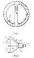
- FIG. 1 illustrates a schematic example of a complex structure that known devices and machines cannot produce by filament winding without successive repetitions of the part.
- This toroidal part formed of two parts in a semicircle A and C comprises a diametrical part B.
- a winding E has been partially represented which we want to perform on part A then on C then on B before continuing again on A, C etc ...
- a device with a coil carrying frame of the type described in FR-A 2 225 372, placed around part A can ensure winding up to the obstacle constituted by the crossmember B. For go to part C you will have to open the frame to move it or use another frame around C which would pick up the wire at the level of the obstacle to make it run through section C.
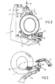
- FIG. 2 shows an L-shaped frame 1 serving as a support for a mandrel 2 of toroidal shape.
- On the base of the frame 1 are mounted two slides 3 on which can move two stirrups 4 each carrying two rollers 5 driven in rotation by a motor 6 via a pin 7. It will be noted that each of the two rollers 5 can deviate more or less from each other depending on the thickness of the mandrel they support, an automatic return mechanism not shown tending to bring them together to grip the mandrel.
- a bracket 8 capable of moving on vertical slides 9, a bracket provided at its end with a stirrup 10 carrying two support and guide rollers 11 also capable of spreading one of the other on their axis 12.
- the mandrel holding device illustrated in FIG. 2 could be produced in a different way, for example as shown in FIG. 4 using at least four arms 14 which clamp the mandrel 2 by holding rollers 15 , the arm-mandrel assembly being able to rotate about an axis 16 movable relative to the neighboring support frame.
- a mechanism would be provided for the arms to retract in turn at the time of the removal of the wire.
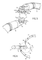
- FIG. 3 The principle implemented, illustrated by FIG. 3, is similar to that of the establishment of a bandage bandage around a member whose natural movement consists for the user, in passing the wound bandage d one hand in the other while unwinding said strip to apply it by winding on the member.
- the device for applying the filament winding must reproduce these movements, also it uses at least two robot arms 16, 17, controlled by a preprogrammed device, which in turn support a fiber distribution cassette 18, each arms performing part of the winding on the mandrel, before the cassette is taken up by the other arm and ensures the other part of the complete winding, the combination of the movement of the two arms and the transfer of the cassette from one to the other allowing the continuous application of fibers on the mandrel 2 along the rotation plane 19.
- the ends of the robot arms 16 and 17 are shown in more detail in FIG. 5. They end with a rotating sleeve 20 on which is mounted a clamp 21 with preprogrammed opening and closing intended to grip one of the two gripping axes of a cassette.
- Each clamp 21 has two semicircular parts 23 capable of moving apart or approaching, parts which are supported by a rotating support 24 with which they cooperate thanks to a sliding link 25; closing or opening is controlled by a mechanism not shown. So when the clamp of one arm closes the other opens and the cassette can pass from one arm to the other. This operation can be done with the cassette stopped and the mandrel stopped. However, advantageously, the transfer can be carried out without immobilizing the cassette, the latter remaining in motion as illustrated by the operating diagram of the transfer shown in FIG. 6.
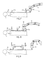
- the cassette must rotate continuously on the winding path 19, around the mandrel 2. While the arm 17 performs its winding part between the point P1 and the point P3 which is diametrically to it opposite, that is to say by covering half of the path 19 and therefore half of the mandrel, the other arm 16 will be returned without cassette from point P2 to point P3 at a higher speed to be in position at point P3 to grab the cassette released by the arm 17.
- the two arms 16 and 17 carry out together, one above the other, a small common path between P3 and P4. During this course, the clamp of the arm 16 closes on a gripping axis of the cassette, then the other clamp of the arm 17 opens, releasing the other axis.
- the station essentially comprises a plate 26 framed by two clamps 27 capable of applying the wire 28 and holding it against the plate. Near one of the pliers 27 is placed a wire cutter 29.
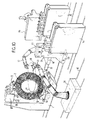
- the universal winding machine as shown by way of example in FIG. 10 makes it possible to adapt to several types of mandrel and to ensure winding by applying the device described.
- the L-shaped frame 1 for supporting the mandrel 2 as described with reference to Figure 2.
- Each of the two robot arms 16 and 17 is mounted on a support base 31, movable on rails 32 , allowing the arms to position themselves correctly relative to the mandrel.
- a wire connection station 33 which can also be moved between the two robot arms can be advanced near the mandrel when it comes to ensuring a bond between sons.
- the tray 26 and the clamps 27 are provided on one side of the station 33.
- This machine therefore makes it possible to produce all types of windings of hollow parts of any desired geometric shape, toric, spherical, cylindrical with rounded ends, straight or curved tubulars. So you can get any type of parts that require you to drop a spool of wire and take it back after having bypassed a possible obstacle.
Landscapes
- Physics & Mathematics (AREA)
- Nonlinear Science (AREA)
- Engineering & Computer Science (AREA)
- Mechanical Engineering (AREA)
- Moulding By Coating Moulds (AREA)
- Manipulator (AREA)
Claims (12)
- Vorrichtung zum Aufwickeln von fadenförmigem Material auf einen Träger beliebiger Form, bei der der Träger oder Wickeldorn auf einer Maschine angeordnet ist, die ihn gegebenenfalls in wenigstens eine Bewegung versetzt, und gemäß der wenigstens eine Fadenabgaberolle auf einem Träger angebracht ist, der zu einer Bewegung relativ zum Wickeldorn angetrieben wird, damit der Faden auf den Träger gemäß einer Bahnkurve gewickelt wird, die sich aus der Kombination der Wickeldornbewegung und der Fadenabgaberollenbewegung ergibt, dadurch gekennzeichnet, daß sie lediglich zwei durch ein vorprogrammiertes System gesteuerte Roboterarme (16, 17) vorsieht, die abwechselnd eine Fadenabgabekassette (18) halten, wobei der eine, mit der Kassette versehene Arm (16) einen Teil einer Aufwickelbahnkurve (19) um den Wickeldorn (2) herum ausführt, an deren Endpunkt die Kassette an den anderen Arm (17) übergeben wird, der den anderen Teil der Bahnkurve bis zum Anfanspunkt des ersten Arms derart ausführt, daß der Faden über den gesamten Umfang des Wickeldorns (2) in einer Bewegung gewickelt wird, die mit dem Anlegen eines Verbandsstreifens um ein Körperglied herum verwandt ist, wenn man den aufgewickelten Streifen unter Abwickeln des Streifens von einer Hand in die andere gleiten läßt.
- Vorrichtung nach Anspruch 1, dadurch gekennzeichnet, daß jeder Roboterarm (16, 17) in einer vorprogrammierten Klemmvorrichtung (21) zum Öffnen und Schließen endet, die dazu vorgesehen ist, einen der zwei Greifbolzen (22) der Kassette (18) zu fassen.
- Vorrichtung nach Anspruch 2, dadurch gekennzeichnet, daß das Ende jedes Roboterarms (16, 17) in einer drehbaren Hülse (20) endet, auf der ein drehbarer Träger (24) der Klemmvorrichtung (21) angebracht ist, der mit zwei halbkreisförmigen Teilen (23) zusammenwirkt, welche dazu befähigt sind, voneinander weg oder aufeinander zu zu laufen.
- Vorrichtung nach Anspruch 1, dadurch gekennzeichnet, daß die zwei Roboterarme (16, 17) zusammen, der eine oberhalb des anderen, eine kurze gemeinsame Bahnkurve (P₁ P₂) und (P₃ P₄) in zwei gegenüberliegenden Bereichen der vollständigen Aufwickelbahnkurve (19) ausführen, um die Übergabe der Kassette (18) von einem Arm an den anderen ohne Unterbrechung der Aufwicklung zu ermöglichen.
- Vorrichtung nach Anspruch 1, dadurch gekennzeichnet, daß der Wickeldorn (2) durch zwei Sätze zweier motorisierter Rollen (5) getragen und an seinem oberen Teil durch Stütz- und Führungsrollen (11) gehalten wird, die gegen ihn anliegen und in vertikalen Gleitschienen (9) beweglich sind.
- Vorrichtung nach Anspruch 1, dadurch gekennzeichnet, daß man eine Verbindungsstation zum Verkleben der Fäden aus der Kassette vorsieht, die aus einer Platte (26), die von zwei Klemmen (27) eingerahmt ist, welche die Fäden (28) festhalten und sie gegen die Platte halten können, aus einem Fadenschneider (29) und aus einer Appliziereinrichtung (30) besteht, die auf die übereinanderliegenden Fäden aufgelegt werden kann, um ihren Klebeverbund sicherzustellen.
- Vorrichtung nach Anspruch 6, dadurch gekennzeichnet, daß die Appliziereinrichtung eine Rolle (30) ist, die fähig ist, gegebenenfalls einen geeigneten Klebstoff zwischen den Fäden zu verteilen.
- Universelle Aufwickelmaschine, welche die Vorrichtung nach einem der Ansprüche 1 bis 7 verwendet, dadurch gekennzeichnet, daß sie mindestens zwei Roboterarme (16, 17) umfaßt, die jeweils auf einem Tragsockel (31) in der Nähe eines den Wickeldorn (2) haltenden Rahmens (1) angebracht sind, wobei die Roboterarme durch eine vorprogrammierte Vorrichtung gesteuert werden und abwechselnd eine Fadenabgabekassette (18) halten, um sie in einer kontinuierlichen Bewegung die Aufwickelbahnkurve (19) um den Wickeldorn herum zurücklegen zu lassen, und dadurch daß sie des weiteren eine Fadenverbindungsstation (33), die es ermöglicht, das Verkleben der Fäden sicherzustellen, sowie Magazine (34 und 35) für die leeren oder vollen Kassetten umfaßt, die durch die Roboterarme bedient werden.
- Maschine nach Anspruch 8, dadurch gekennzeichnet, daß die Tragsockel (31) zur variablen Positionierung der Arme gegenüber dem Rahmen auf Schienen (32) verschiebbar sind.
- Maschine nach Anspruch 8, dadurch gekennzeichnet, daß der Träger des Wickeldorns (2) ein L-förmiger Rahmen (1) ist, an dessen Basis die motorisierten, tragenden Rollen (5) für den Wickeldorn (2) über Bügel (4) auf Gleitschienen (3) angebracht sind.
- Maschine nach Anspruch 8 oder 10, dadurch gekennzeichnet, daß auf dem vertikalen Teil des Rahmens (1) ein Tragarm (8) befestigt ist, der sich auf den vertikalen Schienen (9) bewegt und der die Stütz- und Führungsrollen (11) für den Wickeldorn (2) trägt.
- Maschine nach Anspruch 8, dadurch gekennzeichnet, daß die Fadenverbindungsstation (33) zwischen den Roboterarmen (16, 17) verschiebbar ist und dadurch, daß sie seitlich die Platte (26) für das Verkleben der Fäden sowie ihre Klemmen (27) und die Appliziereinrichtung trägt.
Applications Claiming Priority (2)
| Application Number | Priority Date | Filing Date | Title |
|---|---|---|---|
| FR8805439 | 1988-04-25 | ||
| FR8805439A FR2630422B1 (fr) | 1988-04-25 | 1988-04-25 | Dispositif pour appliquer un enroulement filamentaire sur un support de forme quelconque et machine a bobiner universelle en comportant application |
Publications (2)
| Publication Number | Publication Date |
|---|---|
| EP0340102A1 EP0340102A1 (de) | 1989-11-02 |
| EP0340102B1 true EP0340102B1 (de) | 1993-06-23 |
Family
ID=9365630
Family Applications (1)
| Application Number | Title | Priority Date | Filing Date |
|---|---|---|---|
| EP89401175A Expired - Lifetime EP0340102B1 (de) | 1988-04-25 | 1989-04-25 | Vorrichtung zum Aufwickeln von fadenförmigem Material auf einen Wickeldorn beliebiger Form und dieselbe verwendende Aufwickelmaschine |
Country Status (7)
| Country | Link |
|---|---|
| US (1) | US5086983A (de) |
| EP (1) | EP0340102B1 (de) |
| JP (1) | JP2654180B2 (de) |
| CA (1) | CA1328442C (de) |
| DE (1) | DE68907263T2 (de) |
| ES (1) | ES2043055T3 (de) |
| FR (1) | FR2630422B1 (de) |
Families Citing this family (31)
| Publication number | Priority date | Publication date | Assignee | Title |
|---|---|---|---|---|
| US5507442A (en) * | 1992-09-10 | 1996-04-16 | Tokin Corporation | Method and apparatus for winding toroidal coils |
| JP3341870B2 (ja) * | 1995-03-17 | 2002-11-05 | 田中精機株式会社 | トロイダルコイル巻線機及び巻線方法 |
| BR9811330A (pt) * | 1997-08-22 | 2000-09-19 | Corning Inc | Método e aparelho para enrolamento de fibra em carretel |
| DE19818386A1 (de) * | 1998-04-24 | 1999-12-02 | Werner Meier | Herstellungsverfahren zur vollautomatischen Produktion von Ringkernspulen |
| DE10132718A1 (de) | 2001-07-05 | 2003-02-13 | Abb T & D Tech Ltd | Verfahren zum Bewickeln eines Dreiphasen-Kabeltransformators mit Koaxialkabel und Wickelvorrichtung hierzu |
| JP2006055952A (ja) * | 2004-08-20 | 2006-03-02 | Asahi Diamond Industrial Co Ltd | 超長尺工具の製造装置および製造方法 |
| WO2011082709A1 (en) * | 2010-01-08 | 2011-07-14 | Vestas Wind Systems A/S | Winding machine |
| JP5697506B2 (ja) * | 2011-03-25 | 2015-04-08 | シキボウ株式会社 | ドライプリフォーム、複合材料からなる環状構造体、及びその製造方法 |
| JP5650596B2 (ja) * | 2011-06-22 | 2015-01-07 | 株式会社ブリヂストン | ケーブルビードの製造方法及びケーブルビードの製造システム |
| JP5833374B2 (ja) * | 2011-08-11 | 2015-12-16 | 株式会社ブリヂストン | ケーブルビードの製造方法とその装置 |
| CN102701028B (zh) * | 2012-04-14 | 2016-05-25 | 冀州市曜荣玻璃钢设备有限责任公司 | 倾斜式卧式缠绕机 |
| JP5652445B2 (ja) * | 2012-08-31 | 2015-01-14 | 株式会社安川電機 | ロボット |
| JP6152286B2 (ja) * | 2013-03-18 | 2017-06-21 | 東洋ゴム工業株式会社 | 搬送装置 |
| DE102013205509B4 (de) * | 2013-03-27 | 2019-02-28 | S-Y Systems Technologies Europe Gmbh | Vorrichtung zum Umwickeln eines Kabelbaums |
| DE102013220798A1 (de) * | 2013-10-15 | 2015-04-16 | Kuka Laboratories Gmbh | Verfahren zum Handhaben von Objekten mittels wenigstens zweier Industrieroboter, und zugehöriger Industrieroboter |
| US9782938B2 (en) * | 2014-03-21 | 2017-10-10 | The Boeing Company | Manufacturing system for composite structures |
| EP2953149B1 (de) * | 2014-06-06 | 2017-04-19 | RUFF GmbH | Vorrichtung und Verfahren zum magazinlosen Bewickeln von Ringkernen |
| EP3069848B1 (de) * | 2015-03-20 | 2019-11-20 | North Thin Ply Technology Sarl | Verfahren zur bildung einer faserverstärkten verbundstruktur |
| SE541534C2 (en) * | 2015-05-29 | 2019-10-29 | Lamiflex Ab | Coil packaging system |
| US10604287B2 (en) * | 2015-05-29 | 2020-03-31 | Lamiflex Ab | Coil packaging system |
| US10870200B2 (en) | 2018-01-29 | 2020-12-22 | Massachusetts Institute Of Technology | Methods and apparatus for tube fabrication |
| JP6991898B2 (ja) * | 2018-03-13 | 2022-02-03 | 三菱重工業株式会社 | 複合材積層装置、及び複合材積層方法 |
| KR102028468B1 (ko) * | 2019-07-15 | 2019-10-04 | (주)디지탈맥스 | 코어 코일의 권선방법 및 이를 위한 권선장치 |
| USD980299S1 (en) | 2020-04-30 | 2023-03-07 | Lamiflex Group Ab | Industrial robot tool |
| SE545823C2 (en) * | 2020-04-30 | 2024-02-13 | Lamiflex Group Ab | Robot Tool, Robot System and Method for Coil Packaging |
| SE547304C2 (en) * | 2020-12-23 | 2025-06-24 | Lamiflex Group Ab | Robot System and Method for Coil Packaging |
| CN113021853B (zh) * | 2021-03-24 | 2022-09-02 | 哈尔滨复合材料设备开发有限公司 | 一种用于生产纤维复合材料环链的缠绕装置及缠绕方法 |
| JP7696284B2 (ja) * | 2021-12-10 | 2025-06-20 | 株式会社ブリヂストン | シフト量制御システム、シフト量制御方法及びプログラム |
| KR102590918B1 (ko) * | 2022-01-06 | 2023-10-19 | 주식회사 블럭나인 | 토로이달 코어 권선장치 |
| SE548091C2 (en) * | 2022-06-22 | 2026-02-27 | Lamiflex Group Ab | Robot system and method for coil packaging with different angular velocities |
| CN115123599A (zh) * | 2022-07-29 | 2022-09-30 | 余姚市三富五金制品有限公司 | 一种异型管缠绕设备与异型管缠绕方法 |
Family Cites Families (7)
| Publication number | Priority date | Publication date | Assignee | Title |
|---|---|---|---|---|
| US2721708A (en) * | 1952-05-09 | 1955-10-25 | Paul H Rogers | Self-centering toroidal core holding and driving fixture |
| US2820598A (en) * | 1956-06-01 | 1958-01-21 | Hughes Aircraft Co | Magnetic toroidal core winding machine |
| US2819850A (en) * | 1956-10-15 | 1958-01-14 | Julian D Mathis | Coil winding machines |
| DE3277340D1 (en) * | 1982-06-18 | 1987-10-22 | Matsushita Electric Industrial Co Ltd | Winding method and winding apparatus therefor |
| FR2537556B1 (fr) * | 1982-12-14 | 1986-03-28 | Puydebois Jean | Machine automatique a bobiner les petits tores |
| DE3430055A1 (de) * | 1984-08-16 | 1986-02-27 | MWB Messwandler-Bau AG, 8600 Bamberg | Verfahren und vorrichtung zum bewickeln von ringkernen, ringspulen, ringkernteilen oder ringspulenteilen |
| JPS63136610A (ja) * | 1986-11-28 | 1988-06-08 | Toshiba Corp | トロイダルコイルの製造装置 |
-
1988
- 1988-04-25 FR FR8805439A patent/FR2630422B1/fr not_active Expired - Fee Related
-
1989
- 1989-04-24 CA CA000597632A patent/CA1328442C/fr not_active Expired - Fee Related
- 1989-04-25 DE DE89401175T patent/DE68907263T2/de not_active Expired - Fee Related
- 1989-04-25 ES ES89401175T patent/ES2043055T3/es not_active Expired - Lifetime
- 1989-04-25 EP EP89401175A patent/EP0340102B1/de not_active Expired - Lifetime
- 1989-04-25 JP JP1105715A patent/JP2654180B2/ja not_active Expired - Fee Related
-
1990
- 1990-11-28 US US07/619,828 patent/US5086983A/en not_active Expired - Lifetime
Also Published As
| Publication number | Publication date |
|---|---|
| US5086983A (en) | 1992-02-11 |
| CA1328442C (fr) | 1994-04-12 |
| JPH02132068A (ja) | 1990-05-21 |
| FR2630422A1 (fr) | 1989-10-27 |
| DE68907263T2 (de) | 1994-01-13 |
| JP2654180B2 (ja) | 1997-09-17 |
| FR2630422B1 (fr) | 1990-08-10 |
| ES2043055T3 (es) | 1993-12-16 |
| DE68907263D1 (de) | 1993-07-29 |
| EP0340102A1 (de) | 1989-11-02 |
Similar Documents
| Publication | Publication Date | Title |
|---|---|---|
| EP0340102B1 (de) | Vorrichtung zum Aufwickeln von fadenförmigem Material auf einen Wickeldorn beliebiger Form und dieselbe verwendende Aufwickelmaschine | |
| EP0419299B1 (de) | Wagen zum Abwickeln von einem Film zu einer Verpackungsmaschine | |
| EP0392933B1 (de) | Verfahren und Vorrichtung zum Schneiden und Schweissen einer Verpackungsfolie | |
| BE1006722A5 (fr) | Dispositif pour enrouler un materiau mince, notamment des sacs en film plastique relies ensemble en un ruban. | |
| EP0475886A1 (de) | Vorrichtung und Verfahren zum Öffnen einer Papierrolle und zum Verbinden von dem Ende einer Papierbahn an das Ende einer anderen Papierbahn | |
| EP0005664A1 (de) | Verfahren zum Führen eines faserförmigen Materials von einer Aufwickelspindel zur anderen sowie Vorrichtung zur Durchführung des Verfahrens | |
| FR2619557A1 (fr) | Dispositif de sortie pour textile en bande | |
| FR3041950A1 (fr) | Alimentation pour fardelage | |
| EP2004534B1 (de) | Verfahren zur herstellung einer wicklung mit getrennten fäden | |
| EP0015223B1 (de) | Vorrichtung zum Binden von Drahtspulen | |
| FR2575135A1 (fr) | Appareil pour former la surface d'extremite d'un emballage cylindrique | |
| FR2650555A1 (fr) | Procede et machine pour deposer une bande de film de facon helicoidale sur les faces verticales d'une charge palettisee | |
| FR2745805A1 (fr) | Machine a derouler des bobines en continu comportant au moins un moyen de deroulage de deux bobines jumelees ou coaxiales simultanement | |
| FR2853332A1 (fr) | Dispositif pour la mise en place et l'enlevement de bobines de fil dans une machine textile | |
| FR2755898A1 (fr) | Fabrication d'un renforcement de carcasse pour pneumatique au moyen de deux demi-renforcements de carcasse | |
| EP0241957B1 (de) | Verfahren und Vorrichtung zum Verbinden zweier Folien, insbesondere Folien von einigen Mikrometern Dicke | |
| CA2965043A1 (fr) | Alimentation de fardelage | |
| EP0325498B1 (de) | Vorrichtung zum Laden und Entladen eines Wickelkörpers zur Behandlung von Schüttgut in Schichten | |
| CH541502A (fr) | Procédé pour teindre un fil en paquet | |
| FR2651761A1 (fr) | Appareil pour la pose automatique notamment d'un ruban adhesif sur un produit. | |
| CH621314A5 (de) | ||
| EP0759004A1 (de) | Verfahren und vorrichtung zum wickelförmigen speichern von kabeln oder dergleichen | |
| CH673998A5 (de) | ||
| FR2558854A1 (fr) | Procede et dispositif pour deposer a plat une reserve de fil de trame sous forme de zig zag | |
| FR2661166A1 (fr) | Dispositif pour le pliage transversal d'une gaine souple continue. |
Legal Events
| Date | Code | Title | Description |
|---|---|---|---|
| PUAI | Public reference made under article 153(3) epc to a published international application that has entered the european phase |
Free format text: ORIGINAL CODE: 0009012 |
|
| AK | Designated contracting states |
Kind code of ref document: A1 Designated state(s): BE CH DE ES GB IT LI NL SE |
|
| 17P | Request for examination filed |
Effective date: 19900502 |
|
| 17Q | First examination report despatched |
Effective date: 19920525 |
|
| GRAA | (expected) grant |
Free format text: ORIGINAL CODE: 0009210 |
|
| ITF | It: translation for a ep patent filed | ||
| AK | Designated contracting states |
Kind code of ref document: B1 Designated state(s): BE CH DE ES GB IT LI NL SE |
|
| PG25 | Lapsed in a contracting state [announced via postgrant information from national office to epo] |
Ref country code: SE Effective date: 19930623 Ref country code: NL Effective date: 19930623 |
|
| REF | Corresponds to: |
Ref document number: 68907263 Country of ref document: DE Date of ref document: 19930729 |
|
| GBT | Gb: translation of ep patent filed (gb section 77(6)(a)/1977) |
Effective date: 19931004 |
|
| NLV1 | Nl: lapsed or annulled due to failure to fulfill the requirements of art. 29p and 29m of the patents act | ||
| REG | Reference to a national code |
Ref country code: ES Ref legal event code: FG2A Ref document number: 2043055 Country of ref document: ES Kind code of ref document: T3 |
|
| PLBE | No opposition filed within time limit |
Free format text: ORIGINAL CODE: 0009261 |
|
| STAA | Information on the status of an ep patent application or granted ep patent |
Free format text: STATUS: NO OPPOSITION FILED WITHIN TIME LIMIT |
|
| PG25 | Lapsed in a contracting state [announced via postgrant information from national office to epo] |
Ref country code: LI Effective date: 19940430 Ref country code: CH Effective date: 19940430 |
|
| 26N | No opposition filed | ||
| REG | Reference to a national code |
Ref country code: CH Ref legal event code: PL |
|
| PGFP | Annual fee paid to national office [announced via postgrant information from national office to epo] |
Ref country code: BE Payment date: 20000622 Year of fee payment: 12 |
|
| PG25 | Lapsed in a contracting state [announced via postgrant information from national office to epo] |
Ref country code: BE Free format text: LAPSE BECAUSE OF NON-PAYMENT OF DUE FEES Effective date: 20010430 |
|
| BERE | Be: lapsed |
Owner name: AEROSPATIALE SOC. NATIONALE INDUSTRIELLE Effective date: 20010430 |
|
| REG | Reference to a national code |
Ref country code: GB Ref legal event code: IF02 |
|
| PGFP | Annual fee paid to national office [announced via postgrant information from national office to epo] |
Ref country code: GB Payment date: 20040423 Year of fee payment: 16 |
|
| PGFP | Annual fee paid to national office [announced via postgrant information from national office to epo] |
Ref country code: ES Payment date: 20040512 Year of fee payment: 16 |
|
| PGFP | Annual fee paid to national office [announced via postgrant information from national office to epo] |
Ref country code: DE Payment date: 20040526 Year of fee payment: 16 |
|
| PG25 | Lapsed in a contracting state [announced via postgrant information from national office to epo] |
Ref country code: IT Free format text: LAPSE BECAUSE OF NON-PAYMENT OF DUE FEES;WARNING: LAPSES OF ITALIAN PATENTS WITH EFFECTIVE DATE BEFORE 2007 MAY HAVE OCCURRED AT ANY TIME BEFORE 2007. THE CORRECT EFFECTIVE DATE MAY BE DIFFERENT FROM THE ONE RECORDED. Effective date: 20050425 Ref country code: GB Free format text: LAPSE BECAUSE OF NON-PAYMENT OF DUE FEES Effective date: 20050425 |
|
| PG25 | Lapsed in a contracting state [announced via postgrant information from national office to epo] |
Ref country code: ES Free format text: LAPSE BECAUSE OF NON-PAYMENT OF DUE FEES Effective date: 20050426 |
|
| PG25 | Lapsed in a contracting state [announced via postgrant information from national office to epo] |
Ref country code: DE Free format text: LAPSE BECAUSE OF NON-PAYMENT OF DUE FEES Effective date: 20051101 |
|
| GBPC | Gb: european patent ceased through non-payment of renewal fee |
Effective date: 20050425 |
|
| REG | Reference to a national code |
Ref country code: ES Ref legal event code: FD2A Effective date: 20050426 |