EP0340102B1 - Device for winding filamentary material onto a support of any shape, and a universal winding machine using the device - Google Patents
Device for winding filamentary material onto a support of any shape, and a universal winding machine using the device Download PDFInfo
- Publication number
- EP0340102B1 EP0340102B1 EP89401175A EP89401175A EP0340102B1 EP 0340102 B1 EP0340102 B1 EP 0340102B1 EP 89401175 A EP89401175 A EP 89401175A EP 89401175 A EP89401175 A EP 89401175A EP 0340102 B1 EP0340102 B1 EP 0340102B1
- Authority
- EP
- European Patent Office
- Prior art keywords
- mandrel
- winding
- support
- cassette
- arm
- Prior art date
- Legal status (The legal status is an assumption and is not a legal conclusion. Google has not performed a legal analysis and makes no representation as to the accuracy of the status listed.)
- Expired - Lifetime
Links
Images
Classifications
-
- B—PERFORMING OPERATIONS; TRANSPORTING
- B65—CONVEYING; PACKING; STORING; HANDLING THIN OR FILAMENTARY MATERIAL
- B65H—HANDLING THIN OR FILAMENTARY MATERIAL, e.g. SHEETS, WEBS, CABLES
- B65H81/00—Methods, apparatus, or devices for covering or wrapping cores by winding webs, tapes, or filamentary material, not otherwise provided for
- B65H81/02—Covering or wrapping annular or like cores forming a closed or substantially closed figure
- B65H81/04—Covering or wrapping annular or like cores forming a closed or substantially closed figure by feeding material obliquely to the axis of the core
-
- B—PERFORMING OPERATIONS; TRANSPORTING
- B29—WORKING OF PLASTICS; WORKING OF SUBSTANCES IN A PLASTIC STATE IN GENERAL
- B29C—SHAPING OR JOINING OF PLASTICS; SHAPING OF MATERIAL IN A PLASTIC STATE, NOT OTHERWISE PROVIDED FOR; AFTER-TREATMENT OF THE SHAPED PRODUCTS, e.g. REPAIRING
- B29C53/00—Shaping by bending, folding, twisting, straightening or flattening; Apparatus therefor
- B29C53/56—Winding and joining, e.g. winding spirally
- B29C53/58—Winding and joining, e.g. winding spirally helically
- B29C53/583—Winding and joining, e.g. winding spirally helically for making tubular articles with particular features
- B29C53/588—Winding and joining, e.g. winding spirally helically for making tubular articles with particular features having a non-linear axis, e.g. elbows, toroids
Definitions
- the invention relates to a device for applying a filament winding to a support of any shape, using at least two robot arms controlled by a preprogrammed device as well as a universal winding machine including application.
- a technique of filament winding consists in making a distribution head describe synthetic or other fibers or threads or other, prepreg or not, a programmed trajectory near a support so that these fibers are placed under tension at the place wanted on it, by unwinding storage reels.
- the filament winding is followed by an impregnation of resin when the fibers are not prepreg, and the final composite material is obtained after polymerization of the fiber-resin assembly.
- This filament winding is provided for example on a solid or hollow mandrel whose external shape corresponds to the internal shape of the hollow parts to be produced.
- this mandrel When this mandrel is full, it must be possible to remove it when the part is formed, this is why it is often made of agglomerated material, hardenable under ambient atmospheric conditions, but destructible after thermal cycles for example by chemical means.
- the mandrel When the mandrel is hollow, it is usually formed of a rigid, metallic or other envelope kept inside the part after polymerization.
- said mandrel For winding, said mandrel is placed on a machine and is generally driven in a rotational movement causing, by winding it on itself, the fiber coming from a spool, itself animated by the complementary movements necessary for coating said mandrel.
- the parts obtained with machines of this kind are spherical or cylindrical envelopes with curved bottoms having one or two orifices necessary for their use and through which the support shaft of the mandrel passes during the filament winding.
- machines which use a frame rotating around a tube animated by a movement in advance relative to said frame. These machines can therefore ensure windings around parts with a spherical or tubular tendency but cannot easily wind parts of toroidal shape.
- a device for the winding of filaments around a toroidal element, a device which consists in supporting said toroidal element by a train of rollers on which it rotates around its axis, and in rotating a device for guiding the material around from the surface of the toroidal element, a relative movement being caused between the guide device and the toroidal element so that the material is wound up, a device being provided to compensate for the change in direction of the toroidal element as a result of the winding of the elongated material on the latter, as described in FR A 2 225 372.
- FR-A 2 537 556 also discloses a device adapted to produce windings on toroidal supports which consists in displacing in axial translation a distributor coil inside the toric support using a movable arm, receiving and moving using a second movable mechanism, said coil upwards so that it is taken up by a third mechanism using an arm identical to the first and movable in translation parallel to the outside of the toric support, the coil being finally supported by a fourth organ which replaces it on the original arm.
- a first object of the present invention therefore consists of a device for applying a filament winding to a support of any shape, in which said support or mandrel is disposed on a machine which optionally gives it at least one movement and according to which at least one coil wire dispensing device is mounted on a support having a movement relative to the mandrel so that the wire is wound on said support along a path resulting from the combination of the movement of the mandrel and the movement of the distribution spool, device according to which only two robot arms controlled by a preprogrammed system, take turns supporting a wire distribution cassette, one of the arms provided with the cassette performing part of a winding path around the mandrel at the end of which the cassette is transferred to the other arm which performs the other part of said course to the starting point of the first arm, such so that the wire is wound around the entire periphery of the mandrel in a movement akin to the establishment of a bandage bandage around a member when the wound bandage is passed through it with one hand
- each robot arm ends in a pre-programmed opening and closing clamp intended to grip one of the two gripping axes of the cassette, the end of each robot arm ending in a rotating sleeve on which a support is mounted. turning of the clamp cooperating with two semicircular parts capable of deviating or approaching. It is expected that the two robot arms will perform together, one above the other, a small common path in two opposite zones of the complete winding path, to allow the transfer of the cassette from one arm to the other without interrupting the hoarseness.
- connection station for bonding the cassette wires, which consists of a plate framed by two clamps which can apply the wires and hold them against the plate, and which also consists of a wire cutter and an applicator member which can be applied to the superimposed wires to ensure their adhesion.
- Another object of the present invention consists of a universal winding machine comprising application of the device which comprises at least two robot arms each mounted on a support base near a frame supporting the mandrel, the robot arms being controlled by a preprogrammed device and supporting in turn a wire distribution cassette to make it carry out in a continuous movement the winding path around said mandrel, and also comprising a wire connection station, making it possible to bond the wires, magazines being provided for empty or full cassettes, served by the robot arms.
- FIG. 1 illustrates a schematic example of a complex structure that known devices and machines cannot produce by filament winding without successive repetitions of the part.
- This toroidal part formed of two parts in a semicircle A and C comprises a diametrical part B.
- a winding E has been partially represented which we want to perform on part A then on C then on B before continuing again on A, C etc ...
- a device with a coil carrying frame of the type described in FR-A 2 225 372, placed around part A can ensure winding up to the obstacle constituted by the crossmember B. For go to part C you will have to open the frame to move it or use another frame around C which would pick up the wire at the level of the obstacle to make it run through section C.
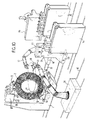
- FIG. 2 shows an L-shaped frame 1 serving as a support for a mandrel 2 of toroidal shape.
- On the base of the frame 1 are mounted two slides 3 on which can move two stirrups 4 each carrying two rollers 5 driven in rotation by a motor 6 via a pin 7. It will be noted that each of the two rollers 5 can deviate more or less from each other depending on the thickness of the mandrel they support, an automatic return mechanism not shown tending to bring them together to grip the mandrel.
- a bracket 8 capable of moving on vertical slides 9, a bracket provided at its end with a stirrup 10 carrying two support and guide rollers 11 also capable of spreading one of the other on their axis 12.
- the mandrel holding device illustrated in FIG. 2 could be produced in a different way, for example as shown in FIG. 4 using at least four arms 14 which clamp the mandrel 2 by holding rollers 15 , the arm-mandrel assembly being able to rotate about an axis 16 movable relative to the neighboring support frame.
- a mechanism would be provided for the arms to retract in turn at the time of the removal of the wire.
- FIG. 3 The principle implemented, illustrated by FIG. 3, is similar to that of the establishment of a bandage bandage around a member whose natural movement consists for the user, in passing the wound bandage d one hand in the other while unwinding said strip to apply it by winding on the member.
- the device for applying the filament winding must reproduce these movements, also it uses at least two robot arms 16, 17, controlled by a preprogrammed device, which in turn support a fiber distribution cassette 18, each arms performing part of the winding on the mandrel, before the cassette is taken up by the other arm and ensures the other part of the complete winding, the combination of the movement of the two arms and the transfer of the cassette from one to the other allowing the continuous application of fibers on the mandrel 2 along the rotation plane 19.
- the ends of the robot arms 16 and 17 are shown in more detail in FIG. 5. They end with a rotating sleeve 20 on which is mounted a clamp 21 with preprogrammed opening and closing intended to grip one of the two gripping axes of a cassette.
- Each clamp 21 has two semicircular parts 23 capable of moving apart or approaching, parts which are supported by a rotating support 24 with which they cooperate thanks to a sliding link 25; closing or opening is controlled by a mechanism not shown. So when the clamp of one arm closes the other opens and the cassette can pass from one arm to the other. This operation can be done with the cassette stopped and the mandrel stopped. However, advantageously, the transfer can be carried out without immobilizing the cassette, the latter remaining in motion as illustrated by the operating diagram of the transfer shown in FIG. 6.
- the cassette must rotate continuously on the winding path 19, around the mandrel 2. While the arm 17 performs its winding part between the point P1 and the point P3 which is diametrically to it opposite, that is to say by covering half of the path 19 and therefore half of the mandrel, the other arm 16 will be returned without cassette from point P2 to point P3 at a higher speed to be in position at point P3 to grab the cassette released by the arm 17.
- the two arms 16 and 17 carry out together, one above the other, a small common path between P3 and P4. During this course, the clamp of the arm 16 closes on a gripping axis of the cassette, then the other clamp of the arm 17 opens, releasing the other axis.
- the station essentially comprises a plate 26 framed by two clamps 27 capable of applying the wire 28 and holding it against the plate. Near one of the pliers 27 is placed a wire cutter 29.
- the universal winding machine as shown by way of example in FIG. 10 makes it possible to adapt to several types of mandrel and to ensure winding by applying the device described.
- the L-shaped frame 1 for supporting the mandrel 2 as described with reference to Figure 2.
- Each of the two robot arms 16 and 17 is mounted on a support base 31, movable on rails 32 , allowing the arms to position themselves correctly relative to the mandrel.
- a wire connection station 33 which can also be moved between the two robot arms can be advanced near the mandrel when it comes to ensuring a bond between sons.
- the tray 26 and the clamps 27 are provided on one side of the station 33.
- This machine therefore makes it possible to produce all types of windings of hollow parts of any desired geometric shape, toric, spherical, cylindrical with rounded ends, straight or curved tubulars. So you can get any type of parts that require you to drop a spool of wire and take it back after having bypassed a possible obstacle.
Landscapes
- Physics & Mathematics (AREA)
- Nonlinear Science (AREA)
- Engineering & Computer Science (AREA)
- Mechanical Engineering (AREA)
- Moulding By Coating Moulds (AREA)
- Manipulator (AREA)
Description
L'invention concerne un dispositif pour appliquer un enroulement filamentaire sur un support de forme quelconque, mettant en oeuvre au moins deux bras robots pilotés par un dispositif préprogrammé ainsi qu'une machine à bobiner universelle en comportant application.The invention relates to a device for applying a filament winding to a support of any shape, using at least two robot arms controlled by a preprogrammed device as well as a universal winding machine including application.
Une technique de l'enroulement filamentaire consiste à faire décrire à une tête de distribution de fibres ou fils synthétiques ou autres, préimprégnés ou non, une trajectoire programmée à proximité d'un support de manière que ces fibres soient posées sous tension à l'endroit voulu sur celui-ci, en se dévidant de bobines de stockage. L'enroulement filamentaire est suivi d'une imprégnation de résine lorsque les fibres ne sont pas préimprégnées, et le matériau composite final est obtenu après polymérisation de l'ensemble fibres-résine. Cet enroulement filamentaire est assuré par exemple sur un mandrin plein ou creux dont la forme extérieure correspond à la forme intérieure des pièces creuses à réaliser. Quand ce mandrin est plein, il faut pouvoir le retirer quand la pièce est formée, c'est pourquoi il est souvent réalisé en matériau aggloméré, durcissable dans les conditions atmosphériques ambiantes, mais destructible après cycles thermiques par exemple par voie chimique. Quand le mandrin est creux, il est habituellement formé d'une enveloppe rigide, métallique ou autre conservée à l'intérieur de la pièce après polymérisation. Pour l'enroulement, ledit mandrin est disposé sur une machine et est généralement animé d'un mouvement de rotation entraînant, en l'enroulant sur lui-même, la fibre venant d'une bobine, elle-même animée des mouvements complémentaires nécessaires au revêtement dudit mandrin. Les pièces obtenues avec des machines de ce genre sont des enveloppes de forme sphérique ou cylindrique à fonds bombés ayant un ou deux orifices nécessaires à leur utilisation et par lesquels passe l'arbre de soutien du mandrin lors de l'enroulement filamentaire.A technique of filament winding consists in making a distribution head describe synthetic or other fibers or threads or other, prepreg or not, a programmed trajectory near a support so that these fibers are placed under tension at the place wanted on it, by unwinding storage reels. The filament winding is followed by an impregnation of resin when the fibers are not prepreg, and the final composite material is obtained after polymerization of the fiber-resin assembly. This filament winding is provided for example on a solid or hollow mandrel whose external shape corresponds to the internal shape of the hollow parts to be produced. When this mandrel is full, it must be possible to remove it when the part is formed, this is why it is often made of agglomerated material, hardenable under ambient atmospheric conditions, but destructible after thermal cycles for example by chemical means. When the mandrel is hollow, it is usually formed of a rigid, metallic or other envelope kept inside the part after polymerization. For winding, said mandrel is placed on a machine and is generally driven in a rotational movement causing, by winding it on itself, the fiber coming from a spool, itself animated by the complementary movements necessary for coating said mandrel. The parts obtained with machines of this kind are spherical or cylindrical envelopes with curved bottoms having one or two orifices necessary for their use and through which the support shaft of the mandrel passes during the filament winding.
Pour le production de tubes en matériaux composites, on connaît également des machines qui utilisent un cadre tournant autour d'un tube animé d'un mouvement d'avance par rapport audit cadre. Ces machines peuvent donc assurer des enroulements autour de pièces à tendance sphériques ou tubulaires mais ne peuvent facilement enrouler des pièces de forme toroïdale. Pour l'enroulement de filaments autour d'un élément toroïdal on connaît un dispositif qui consiste à faire supporter ledit élément toroïdal par un train de rouleaux sur lesquels il tourne autour de son axe, et à faire tourner un dispositif de guidage de la matière autour de la surface de l'élément toroïdal, un mouvement relatif étant provoqué entre le dispositif de guidage et l'élément toroïdal pour que la matière soit enroulée, un dispositif étant prévu pour compenser le changement de direction de l'élément toroïdal par suite de l'enroulement de la matière allongée sur ce dernier, comme décrit dans le FR A 2 225 372.For the production of tubes made of composite materials, machines are also known which use a frame rotating around a tube animated by a movement in advance relative to said frame. These machines can therefore ensure windings around parts with a spherical or tubular tendency but cannot easily wind parts of toroidal shape. For the winding of filaments around a toroidal element, a device is known which consists in supporting said toroidal element by a train of rollers on which it rotates around its axis, and in rotating a device for guiding the material around from the surface of the toroidal element, a relative movement being caused between the guide device and the toroidal element so that the material is wound up, a device being provided to compensate for the change in direction of the toroidal element as a result of the winding of the elongated material on the latter, as described in FR
Dans ce genre de machine à bobiner les mandrins toriques il y a nécessairement un cadre porteur de bobines de fibres qui pénètre à l'intérieur du tore à la manière de deux maillons successifs d'une chaîne. Pour la mise en oeuvre de l'enroulement il faut donc nécessairement ouvrir ce cadre pour le faire rentrer dans le tore et ensuite l'y ajuster avant de recommencer l'action inverse en fin d'enroulement. Cela implique un montage difficile et des moyens annexes lourds et volumineux. De plus, s'il se présente un obstacle sur le support torique par exemple une traverse disposée diamétralement, il faut interrompre le bobinage et déplacer le cadre avant de reprendre le bobinage de l'autre côté de l'obstacle. Par conséquent si on recherche une pièce de ce type ou si d'une façon générale on veut obtenir par enroulement filamentaire une pièce comportant un ou des obstacles à l'enroulement en continu, l'utilisation d'une tête ou d'un cadre de distribution s'avère pratiquement impossible. On connaît aussi par le FR-A 2 537 556 un dispositif adapté à réaliser des bobinages sur des supports toriques qui consiste à déplacer en translation axiale une bobine distributrice à l'intérieur du support torique à l'aide d'un bras mobile, à recevoir et déplacer à l'aide d'un second mécanisme mobile, ladite bobine vers le haut pour qu'elle soit reprise par un troisième mécanisme utilisant un bras identique au premier et déplaçable en translation parallèlement à l'extérieur du support torique, la bobine étant enfin prise en charge par un quatrième organe qui la replace sur le bras original.In this kind of machine for winding toric mandrels there is necessarily a frame carrying spools of fibers which penetrates inside the torus in the manner of two successive links of a chain. For the implementation of the winding, it is therefore necessary to open this frame to bring it into the torus and then adjust it before repeating the opposite action at the end of winding. This implies a difficult assembly and heavy and bulky additional means. In addition, if there is an obstacle on the toroidal support, for example a cross member arranged diametrically, it is necessary to interrupt the winding and move the frame before resuming the winding on the other side of the obstacle. Consequently if one is looking for a part of this type or if in general one wishes to obtain by filament winding a part comprising one or more obstacles to the continuous winding, the use of a head or a frame of distribution is almost impossible. FR-A 2 537 556 also discloses a device adapted to produce windings on toroidal supports which consists in displacing in axial translation a distributor coil inside the toric support using a movable arm, receiving and moving using a second movable mechanism, said coil upwards so that it is taken up by a third mechanism using an arm identical to the first and movable in translation parallel to the outside of the toric support, the coil being finally supported by a fourth organ which replaces it on the original arm.
On imagine aisément que pour assurer un bobinage correct sous tension constante à partir de ces quatre mécanismes porteurs de bobines, qui doivent se déplacer chacun selon une trajectoire précise, les problèmes de synchronisation ne soient pas simples à résoudre, sans parler de la complexité des agencements de ces mécanismes.It is easy to imagine that to ensure correct winding under constant tension from these four coil-carrying mechanisms, which must each move along a precise trajectory, the synchronization problems are not simple to solve, not to mention the complexity of the arrangements of these mechanisms.
En outre avec les machines précédemment décrites, il est difficile de passer d'une pièce à l'autre si celles-ci ne sont pas de la même forme et de la même dimension, sans modifier ou changer le cadre et même le support de mandrin. Enfin les éléments toroïdaux en question doivent avoir au moins leur forme extérieure régulière pour pouvoir tourner aisément sur leurs rouleaux supports pendant l'opération d'enroulement. Ces machines conviennent donc pour réaliser des séries de pièce toroïdales identiques mais sont évidemment trop complexes pour être utilisées pour former par exemple des assemblages de pièces tubulaires. Inversement les machines évoquées plus haut destinées à former des pièces à tendance sphérique ou à tendance tubulaire, sont bien incapables de traiter les pièces toroïdales irrégulières ou d'autres pièces de forme quelconque.Furthermore with the machines described above, it is difficult to move from one part to another if they are not of the same shape and the same dimension, without modifying or changing the frame and even the mandrel support. . Finally, the toroidal elements in question must have at least their regular external shape in order to be able to easily rotate on their support rollers during the winding operation. These machines are therefore suitable for producing identical series of toroidal parts but are obviously too complex to be used for forming, for example assemblies of tubular parts. Conversely, the machines mentioned above intended to form parts with a spherical tendency or with a tubular tendency, are quite incapable of treating irregular toroidal parts or other parts of any shape.
C'est pourquoi la Demanderesse a imaginé un dispositif original pour appliquer un bobinage filamentaire, et une machine pour la mise en oeuvre du dispositif, qui permet de réaliser n'importe quelle pièce par enroulement filamentaire en évitant les inconvénients propres aux machines connues. Cette machine par son universalité permet de franchir les obstacles des supports compliqués et donc de réaliser des structures tubulaires diverses, car elle est capable d'assembler des tubes entre eux. De plus puisqu'elle permet de s'affranchir d'un cadre porteur de bobines qui pénètre dans une pièce complexe telle qu'une pièce de forme torique, elle évite les inconvénients inhérents à ce cadre qui sont notamment son ouverture ou sa fermeture par rapport au mandrin ainsi que son inadaptabilité géométrique immédiate à la forme de la pièce souhaitée, et aussi son volume.This is why the Applicant has imagined an original device for applying a filament winding, and a machine for implementing the device, which makes it possible to produce any part by filament winding while avoiding the drawbacks specific to known machines. This machine by its universality makes it possible to overcome the obstacles of complicated supports and therefore to produce various tubular structures, because it is able to assemble tubes together. In addition since it makes it possible to get rid of a frame carrying coils which penetrates into a complex part such as a part of toroidal shape, it avoids the drawbacks inherent in this frame which are in particular its opening or closing relative to to the mandrel as well as its immediate geometric unsuitability for the shape of the desired part, and also its volume.
Enfin elle ne nécessite pas la mise en oeuvre de beaucoup d'organes mécaniques et va dans le sens d'une simplification et d'une meilleure efficacité.Finally, it does not require the use of many mechanical members and goes in the direction of simplification and better efficiency.
Un premier objet de la présente invention consiste donc en un dispositif pour appliquer un enroulement filamentaire sur un support de forme quelconque, dans lequel ledit support ou mandrin est disposé sur une machine qui lui imprime éventuellement au moins un mouvement et selon lequel au moins une bobine de distribution de fil est montée sur un support animé d'un mouvement relatif par rapport au mandrin pour que le fil soit enroulé sur ledit support selon une trajectoire résultant de la combinaison du mouvement du mandrin et du mouvement de la bobine de distribution, dispositif selon lequel seulement deux bras de robot pilotés par un système préprogrammé, supportent à tour de rôle une cassette de distribution de fil, l'un des bras pourvu de la cassette effectuant une partie d'un parcours d'enroulement autour du mandrin au terme duquel la cassette est transférée à l'autre bras qui effectue l'autre partie dudit parcours jusqu'au point de départ du premier bras, de telle sorte que le fil soit enroulé sur tout le pourtour de mandrin selon un mouvement qui s'apparente à la mise en place d'une bande de pansement autour d'un membre quand on y fait passer la bande enroulée d'une main dans l'autre en dévidant ladite bande.A first object of the present invention therefore consists of a device for applying a filament winding to a support of any shape, in which said support or mandrel is disposed on a machine which optionally gives it at least one movement and according to which at least one coil wire dispensing device is mounted on a support having a movement relative to the mandrel so that the wire is wound on said support along a path resulting from the combination of the movement of the mandrel and the movement of the distribution spool, device according to which only two robot arms controlled by a preprogrammed system, take turns supporting a wire distribution cassette, one of the arms provided with the cassette performing part of a winding path around the mandrel at the end of which the cassette is transferred to the other arm which performs the other part of said course to the starting point of the first arm, such so that the wire is wound around the entire periphery of the mandrel in a movement akin to the establishment of a bandage bandage around a member when the wound bandage is passed through it with one hand in the another by unwinding said strip.
Avantageusement chaque bras de robot se termine par une pince à ouverture et fermeture préprogrammée destinée à se saisir d'un des deux axes de préhension de la cassette l'extrémité de chaque bras de robot se terminant par un manchon tournant sur lequel est monté un support tournant de la pince coopérant avec deux parties demi-circulaires susceptibles de s'écarter ou de se rapprocher. On prévoit que les deux bras de robot effectuent ensemble, l'un au-dessus de l'autre, un petit parcours commun en deux zones opposées du parcours d'enroulement complet, pour permettre le transfert de la cassette d'un bras à l'autre sans interrompre l'enroument.Advantageously, each robot arm ends in a pre-programmed opening and closing clamp intended to grip one of the two gripping axes of the cassette, the end of each robot arm ending in a rotating sleeve on which a support is mounted. turning of the clamp cooperating with two semicircular parts capable of deviating or approaching. It is expected that the two robot arms will perform together, one above the other, a small common path in two opposite zones of the complete winding path, to allow the transfer of the cassette from one arm to the other without interrupting the hoarseness.
Selon une autre caractéristique particulière de l'invention, on prévoit un poste de liaison pour le collage des fils de cassette, qui consiste en un plateau encadré de deux pinces pouvant appliquer les fils et les maintenir contre le plateau, et qui consiste aussi en un coupe-fil et en un organe applicateur pouvant s'appliquer sur les fils superposés pour assurer leur adhésion.According to another particular characteristic of the invention, there is provided a connection station for bonding the cassette wires, which consists of a plate framed by two clamps which can apply the wires and hold them against the plate, and which also consists of a wire cutter and an applicator member which can be applied to the superimposed wires to ensure their adhesion.
Un autre objet de la présente invention consiste en une machine à bobiner universelle comportant application du dispositif qui comporte au moins deux bras de robot montés chacun sur un socle support à proximité d'un bâti supportant le mandrin, les bras de robot étant pilotés par un dispositif préprogrammé et supportant à tour de rôle une cassette de distribution de fil pour lui faire effectuer en un mouvement continu le parcours d'enroulement autour dudit mandrin, et comportant également un poste de liaison des fils, permettant d'assurer le collage des fils, des magasins étant prévus pour les cassettes vides ou pleines, desservis par les bras de robot.Another object of the present invention consists of a universal winding machine comprising application of the device which comprises at least two robot arms each mounted on a support base near a frame supporting the mandrel, the robot arms being controlled by a preprogrammed device and supporting in turn a wire distribution cassette to make it carry out in a continuous movement the winding path around said mandrel, and also comprising a wire connection station, making it possible to bond the wires, magazines being provided for empty or full cassettes, served by the robot arms.
D'autres caractéristiques particulières et avantages de l'invention apparaîtront maintenant à la lecture de la description qui va suivre d'exemples non limitatifs de réalisation de l'invention qui font référence aux dessins annexés dans lesquels :
- la figure 1 est une vue schématique en plan d'un type de mandrin pouvant recevoir un enroulement selon le dispositif de l'invention ;
- la figure 2 représente en perspective le support d'un mandrin toroïdal et la figure 3, schématiquement, ledit mandrin et les bras de robot assurant l'enroulement ;
- la figure 4 est une vue en coupe d'une variante de support de mandrin ;
- la figure 5 est une vue en perspective à plus grande échelle des extrémités des bras de robot montrant les pinces de préhension.
- la figure 6 représente schématiquement en plan les phases d'enroulement à l'aide des deux bras de robot ;
- les figures 7 à 9 illustrent schématiquement le fonctionnement du poste de liaison des fils.
- la figure 10 représente en perspective une machine à bobiner universelle.
- Figure 1 is a schematic plan view of a type of mandrel capable of receiving a winding according to the device of the invention;
- Figure 2 shows in perspective the support of a toroidal mandrel and Figure 3, schematically, said mandrel and the robot arms ensuring the winding;
- Figure 4 is a sectional view of an alternative mandrel support;
- Figure 5 is an enlarged perspective view of the ends of the robot arms showing the grippers.
- Figure 6 schematically shows in plan the winding phases using the two robot arms;
- Figures 7 to 9 schematically illustrate the operation of the wire connection station.
- Figure 10 shows in perspective a universal winding machine.
La figure 1 illustre un exemple schématique de structure complexe que les dispositifs et machines connues ne peuvent réaliser par enroulement filamentaire sans des reprises successives de la pièce. Cette pièce toroïdale formée de deux parties en demi-cercle A et C, comporte une partie diamétrale B. On a représenté partiellement un enroulement E que l'on veut effectuer sur la partie A puis sur C puis sur B avant de continuer à nouveau sur A, C etc... Un dispositif à cadre porteur de bobine du genre décrit dans le FR-A 2 225 372, placé autour de la partie A pourra assurer l'enroulement jusqu'a l'obstacle constitué par la traverse B. Pour passer à la partie C il faudra donc ouvrir le cadre pour le déplacer ou utiliser un autre cadre autour de C qui reprendrait le fil au niveau de l'obstacle pour lui faire parcourir la section C. Puis un nouvel obstacle A se présente si l'on veut passer de la section C à travers B, un autre de B vers A etc... . Chaque obstacle nécessite donc une reprise de l'enroulement, qui rend la réalisation techniquement très difficile à l'aide des dispositifs connus. L'invention décrite en référence aux figures 2 à 10 permettrait de réaliser notamment ce type de structure.FIG. 1 illustrates a schematic example of a complex structure that known devices and machines cannot produce by filament winding without successive repetitions of the part. This toroidal part formed of two parts in a semicircle A and C, comprises a diametrical part B. A winding E has been partially represented which we want to perform on part A then on C then on B before continuing again on A, C etc ... A device with a coil carrying frame of the type described in FR-
On a représenté à la figure 2 un bâti 1 en forme de L servant de support à un mandrin 2 de forme toroïdale. Sur la base du bâti 1 sont montés deux coulisseaux 3 sur lesquels peuvent se déplacer deux étriers 4 portant chacun deux galets 5 entraînés en rotation par un moteur 6 par l'intermédiaire d'un axe 7. On notera que chacun des deux galets 5 peut s'écarter plus ou moins de l'autre en fonction de l'épaisseur du mandrin qu'ils supportent, un mécanisme de rappel automatique non représenté tendant à les rapprocher pour enserrer le mandrin. Sur la partie verticale du bâti 1, est fixée une potence 8 susceptible de se déplacer sur des coulisseaux verticaux 9, potence munie à son extrémité d'un étrier 10 porteur de deux galets d'appui et de guidage 11 également susceptibles de s'écarter l'un de l'autre sur leur axe 12. Le poids de la potence ou une force verticale exercée sur elle selon la flèche 13, maintient une pression constante sur le sommet du mandrin 2, même si sa surface extérieure de roulement n'est pas régulière, du fait de sa mobilité sur les coulisseaux 9. On comprend que, dans cette position, le mandrin repose verticalement sur les jeux de galets 5 qui l'entraînent en rotation, tout en restant maintenu par les galets de guidage supérieurs 11.FIG. 2 shows an L-
Le dispositif de maintien du mandrin illustré à la figure 2 pourrait être réalisé de façon différente, par exemple comme représenté à la figure 4 à l'aide de bras 14 au moins au nombre de quatre qui serrent le mandrin 2 par des galets de maintien 15, l'ensemble bras-mandrin pouvant tourner autour d'un axe 16 mobile par rapport au bâti support voisin. Un mécanisme serait prévu pour que les bras s'escamotent à tour de rôle au moment de la dépose du fil . On a représenté en pointillé un bras 14 prenant une position écartée à ce moment. Il faut donc prévoir au moins un certain nombre de bras pour tenir le mandrin et lui faire effectuer sa rotation, sans qu'il soit déséquilibré quand un des bras s'escamote.The mandrel holding device illustrated in FIG. 2 could be produced in a different way, for example as shown in FIG. 4 using at least four
Le mandrin étant ainsi maintenu par exemple grâce aux supports selon la figure 2, on va décrire maintenant le dispositif pour lui appliquer l'enroulement filamentaire. Le principe mis en oeuvre, illustré par la figure 3, s'apparente à celui de la mise en place d'une bande de pansement autour d'un membre dont le mouvement naturel consiste pour l'utilisateur, à faire passer la bande enroulée d'une main dans l'autre tout en dévidant ladite bande pour l'appliquer par enroulement sur le membre. En l'occurence le dispositif pour appliquer le bobinage filamentaire doit reproduire ces mouvements, aussi il utilise au moins deux bras de robot 16, 17, pilotés par un dispositif préprogrammé, qui supportent à tour de rôle une cassette 18 de distribution de fibre, chacun des bras effectuant une partie de l'enroulement sur le mandrin, avant que la cassette ne soit reprise par l'autre bras et n'assure l'autre partie de l'enroulement complet, la combinaison du mouvement des deux bras et le transfert de la cassette de l'un à l'autre permettant l'application en continu de fibres sur le mandrin 2 selon le plan de rotation 19. Les extrémités des bras de robot 16 et 17 sont représentées plus en détail à la figure 5. Ils se terminent par un manchon tournant 20 sur lequel est montée une pince 21 à ouverture et fermeture préprogrammée destinée à se saisir d'un des deux axes de préhension d'une cassette. Sur le manchon du bras supérieur 17 la pince est représentée ouverte tandis que sur le manchon du bras inférieur 16 elle est représentée fermée. Chaque pince 21 comporte deux parties demi-circulaires 23 susceptibles de s'écarter ou de se rapprocher, parties qui sont soutenues par un support tournant 24 avec lequel elles coopèrent grâce à une liaison coulissante 25 ; la fermeture ou l'ouverture est commandée par un mécanisme non représenté. Ainsi quand la pince d'un bras se ferme l'autre s'ouvre et la cassette peut passer d'un bras à l'autre. Cette opération peut se faire cassette arrêtée et mandrin arrêté. Néanmoins, avantageusement, le transfert peut se faire sans immobilisation de cassette, celle-ci restant en mouvement comme l'illustre le schéma de fonctionnement du transfert représenté à la figure 6.The mandrel thus being held for example by means of the supports according to FIG. 2, we will now describe the device for applying the filament winding to it. The principle implemented, illustrated by FIG. 3, is similar to that of the establishment of a bandage bandage around a member whose natural movement consists for the user, in passing the wound bandage d one hand in the other while unwinding said strip to apply it by winding on the member. In this case the device for applying the filament winding must reproduce these movements, also it uses at least two
On voit que la cassette doit effectuer une rotation continue sur le parcours d'enroulement 19, autour du mandrin 2. Pendant que le bras 17 effectue sa partie de bobinage entre le point P₁ et le point P₃ qui lui est diamétralement opposé, c'est-à-dire en couvrant la moitié du parcours 19 et par conséquent la moitié du mandrin, l'autre bras 16 sera revenu sans cassette du point P₂ au point P₃ à une vitesse plus élevée pour être en position au point P₃ pour saisir la cassette libérée par le bras 17. Les deux bras 16 et 17 effectuent ensemble, l'un au dessus de l'autre un petit parcours commun entre P₃ et P₄. Durant ce parcours la pince du bras 16 se ferme sur un axe de préhension de la cassette puis l'autre pince du bras 17 s'ouvre libérant l'autre axe. A partir de P₄ la cassette entraînée par le bras 16 jusqu'au point P₂ effectue l'autre moitié du bobinage. Le bras 17 étant revenu en P₁, le transfert de la cassette du bras 16 au bras 17 se fera de façon analogue durant le parcours commun P₁-P₂. On obtient ainsi une rotation continue de la cassette 18 autour du mandrin, à vitesse constante, et indexée sur la rotation dudit mandrin.We see that the cassette must rotate continuously on the winding
Les cassettes de distribution ne pouvant renfermer une quantité inépuisable de fils, quand les enroulements sont importants, il convient de prévoir le remplacement d'une cassette vide par une pleine. Il faut à ce moment là assurer la liaison entre le fil appliqué sur le mandrin et celui de la cassette neuve. Cela s'effectue au poste de liaison représenté aux figures 7 à 9. Le poste comprend essentiellement un plateau 26 encadré de deux pinces 27 susceptibles d'appliquer le fil 28 et le maintenir contre le plateau. A proximité d'une des pinces 27 est placé un coupe-fil 29.Since the distribution cassettes cannot contain an inexhaustible quantity of wires, when the windings are large, it is advisable to provide for the replacement of an empty cassette by a full one. It is then necessary to ensure the connection between the wire applied to the mandrel and that of the new cassette. This is done at the connection station shown in Figures 7 to 9. The station essentially comprises a
Quand on veut relier un fil 28 provenant de la pièce à bobiner (mandrin 2) au fil d'une cassette neuve maintenue par un bras de robot, on commence par serrer une section de fil 28 contre le plateau 26 par la pince 27a le plus éloignée du mandrin 2 (figure 7). Puis on coupe l'extrémité débordante de fil entre pince et cassette à l'aide du coupe-fil 29. La cassette vide ou presque vide 18 maintenue par le bras de robot 17 peut alors être dégagée vers un lieu de stockage prévu à cet effet. Pendant ce temps un autre bras de robot 16 va saisir une cassette pleine 18 dans un présentoir et l'amener au poste de liaison. L'extrémité du fil libre pendant de cette cassette sera amenée sur le plateau jusqu'à l'autre pince 27b la plus proche du mandrin 2 pour y être maintenue et ainsi cette portion de fil reposera sur l'autre portion précédente, un guidage pouvant favoriser leur superposition (figure 8). Les deux fils étant ainsi superposés, le deuxième fil étant par ailleurs, également maintenu par la cassette elle-même, une roulette 30 constituant l'organe applicateur vient alors rouler sur les fils pour assurer leur collage, par exemple en distribuant entre eux un adhésif approprié. Puis les pinces 27a et 27b se dégagent du plateau 26. La cassette neuve 18 s'écarte ensuite du plateau 26 (figure 9) ce qui permet de compléter le collage des fils, à l'aide de la roulette 30, sur toute la longueur du poste de liaison. Le bras 16 et sa cassette peuvent alors revenir sur la trajectoire de bobinage en avalant la partie des fils collés grâce à un système à ressort incorporé dont dispose la cassette. Le bobinage de la pièce peut donc continuer jusqu'au prochain changement de bobine.When we want to connect a
Grâce au dispositif précédemment décrit, on peut donc assurer tous types de bobinages.Thanks to the device described above, it is therefore possible to ensure all types of windings.
La machine à bobiner universelle telle que présentée à titre d'exemple à la figure 10 permet de s'adapter à plusieurs types de mandrin et d'assurer un bobinage en mettant en application le dispositif décrit. On reconnaît sur cette figure le bâti 1 en forme de L permettant de supporter le mandrin 2 comme décrit en référence à la figure 2. Chacun des deux bras de robot 16 et 17 est monté sur un socle-support 31, déplaçable sur des rails 32, permettant aux bras de se positionner correctement par rapport au mandrin. Un poste de liaison de fils 33 également déplaçable entre les deux bras robot peut être avancé à proximité du mandrin quand il s'agit d'assurer une liaison entre fils. Le plateau 26 et les pinces 27 sont prévus sur un côté du poste 33. Enfin on prévoit à proximité un magasin 34 de cassettes vides et un autre magasin 35 de cassettes pleines, également déplaçables pour pouvoir se rapprocher du poste 33 quand on effectue une liaison. La machine est préprogrammée et commandée à partir d'un poste fixe voisin de contrôle et de commande 36.The universal winding machine as shown by way of example in FIG. 10 makes it possible to adapt to several types of mandrel and to ensure winding by applying the device described. We recognize in this figure the L-shaped
Cette machine permet donc de réaliser tous les types de bobinages de pièces creuses de toute formes géométriques souhaitées, toriques, sphériques, cylindriques à bouts bombés, tubulaires rectilignes ou courbes. Ainsi on peut obtenir tout type de pièces nécessitant de lâcher une bobine de fil et la reprendre après avoir contourné un éventuel obstacle.This machine therefore makes it possible to produce all types of windings of hollow parts of any desired geometric shape, toric, spherical, cylindrical with rounded ends, straight or curved tubulars. So you can get any type of parts that require you to drop a spool of wire and take it back after having bypassed a possible obstacle.
Claims (12)
- Device for applying a filament winding to a support of any shape, wherein the said support or mandrel is placed on a machine which imparts thereto, optionally, at least one movement and according to which at least one thread dispensing reel is mounted on a support caused to execute a movement relative to the mandrel so that the thread is wound onto the said support along a path resulting from the combination of the movement of the mandrel and the movement of the dispensing reel, characterised in that it utilises only two robot arms (16, 17) controlled by a pre-programmed system and each in turn supporting a thread dispensing cassette (18), one of the arms (16) provided with the cassette travelling over one part of a winding path (19) about the mandrel (2) at the end of which the cassette is transferred to the other arm (17) which travels over the other part of the said path up to the point of departure of the first arm, in such a way that the thread is wound round the entire periphery of the mandrel (2) in a movement which is analogous to the winding of a bandage round a limb when the rolled bandage is passed from one hand to the other as the said bandage is unwound.
- Device according to Claim 1, characterised in that each robot arm (16,17) ends in a pincer (21) with preprogrammed opening and closing, designed to seize one of the two gripping spindles (22) of the cassette (18).
- Device according to Claim 2, characterised in that the end of each robot arm (16,17) ends in a rotary sleeve (20) on which is mounted a rotary support (24) of the pincer (21), co-operating with two semi-circular portions (23) capable of moving apart or coming together.
- Device according to Claim 1, characterised in that the two robot arms (16,17) travel together, one above the other, over a short common path (P₁ P₂) and (P₃ P₄) in two opposite zones of the complete winding path (19), to permit the transfer of the cassette (18) from one arm to the other without interrupting the winding operation.
- Device according to Claim 1, characterised in that the mandrel (2) is supported by two sets of two motor-driven rollers (5) and held in its upper part by supporting and guiding rollers (11) which are urged against it and are movable on vertical slides (9).
- Device according to Claim 1, characterised in that a joining station is provided for bonding together the cassette threads, which station consists of a plate (26) framed by two grippers (27) capable of pressing the threads (28) and holding them against the plate, and which also consists of a thread cutter (29) and an applicator member (30) that can be applied to the superposed threads to ensure their adhesion.
- Device according to Claim 6, characterised in that the applicator member is a roller (30) optionally capable of distributing a suitable adhesive between the threads.
- Universal winding machine comprising the application of the device according to one of Claims 1 to 7, characterised in that it comprises at least two robot arms (16, 17), each mounted on a support base (31) in the vicinity of a frame (1) supporting the mandrel (2), the robot arms being controlled by a pre-programmed device and supporting each in turn a thread dispensing cassette (18) to cause it to travel in a continuous movement along the winding path (19) round the said mandrel, and in that it also comprises a thread joining station (33), permitting the bonding of the threads, and magazines (34 and 35) for the empty or full cassettes, served by the robot arms.
- Machine according to Claim 8, characterised in that the support bases (31) are movable on rails (32) for the variable positioning of the arms in relation to the frame.
- Machine according to Claim 8, characterised in that the support of the mandrel (2) is an L-shaped frame (1), on the base of which frame motor-driven rollers (5) for carrying the mandrel (2) are mounted by way of yokes (4) on slides (3).
- Machine according to one of Claims 8 or 10, characterised in that on the vertical portion of the frame (1) is fixed a jib (8) moving on vertical slides (9) and which carries rollers (11) for supporting and guiding the mandrel (2).
- Machine according to Claim 8, characterised in that the thread joining station (33) is movable between the robot arms (16, 17) and in that it carries on the side the plate (26) for the bonding of the threads, as well as its grippers (27) and the applicator member.
Applications Claiming Priority (2)
| Application Number | Priority Date | Filing Date | Title |
|---|---|---|---|
| FR8805439A FR2630422B1 (en) | 1988-04-25 | 1988-04-25 | DEVICE FOR APPLYING A FILAMENTARY WINDING ON ANY FORMED SUPPORT AND UNIVERSAL WINDING MACHINE INCLUDING APPLICATION |
| FR8805439 | 1988-04-25 |
Publications (2)
| Publication Number | Publication Date |
|---|---|
| EP0340102A1 EP0340102A1 (en) | 1989-11-02 |
| EP0340102B1 true EP0340102B1 (en) | 1993-06-23 |
Family
ID=9365630
Family Applications (1)
| Application Number | Title | Priority Date | Filing Date |
|---|---|---|---|
| EP89401175A Expired - Lifetime EP0340102B1 (en) | 1988-04-25 | 1989-04-25 | Device for winding filamentary material onto a support of any shape, and a universal winding machine using the device |
Country Status (7)
| Country | Link |
|---|---|
| US (1) | US5086983A (en) |
| EP (1) | EP0340102B1 (en) |
| JP (1) | JP2654180B2 (en) |
| CA (1) | CA1328442C (en) |
| DE (1) | DE68907263T2 (en) |
| ES (1) | ES2043055T3 (en) |
| FR (1) | FR2630422B1 (en) |
Families Citing this family (31)
| Publication number | Priority date | Publication date | Assignee | Title |
|---|---|---|---|---|
| US5507442A (en) * | 1992-09-10 | 1996-04-16 | Tokin Corporation | Method and apparatus for winding toroidal coils |
| JP3341870B2 (en) * | 1995-03-17 | 2002-11-05 | 田中精機株式会社 | Toroidal coil winding machine and winding method |
| WO1999010268A1 (en) * | 1997-08-22 | 1999-03-04 | Corning Incorporated | Method and apparatus for winding fiber on a spool |
| DE19818386A1 (en) * | 1998-04-24 | 1999-12-02 | Werner Meier | Automatic manufacture of ring coils |
| DE10132718A1 (en) | 2001-07-05 | 2003-02-13 | Abb T & D Tech Ltd | Method for winding a three-phase cable transformer with coaxial cable and winding device therefor |
| JP2006055952A (en) * | 2004-08-20 | 2006-03-02 | Asahi Diamond Industrial Co Ltd | Apparatus and method for manufacturing ultra-long tool |
| WO2011082709A1 (en) * | 2010-01-08 | 2011-07-14 | Vestas Wind Systems A/S | Winding machine |
| JP5697506B2 (en) | 2011-03-25 | 2015-04-08 | シキボウ株式会社 | Dry preform, annular structure made of composite material, and manufacturing method thereof |
| JP5650596B2 (en) * | 2011-06-22 | 2015-01-07 | 株式会社ブリヂストン | Cable bead manufacturing method and cable bead manufacturing system |
| JP5833374B2 (en) * | 2011-08-11 | 2015-12-16 | 株式会社ブリヂストン | Cable bead manufacturing method and apparatus |
| CN102701028B (en) * | 2012-04-14 | 2016-05-25 | 冀州市曜荣玻璃钢设备有限责任公司 | Tilting Horizontal type winding machine |
| JP5652445B2 (en) * | 2012-08-31 | 2015-01-14 | 株式会社安川電機 | robot |
| JP6152286B2 (en) * | 2013-03-18 | 2017-06-21 | 東洋ゴム工業株式会社 | Transport device |
| DE102013205509B4 (en) * | 2013-03-27 | 2019-02-28 | S-Y Systems Technologies Europe Gmbh | Device for wrapping a cable harness |
| DE102013220798A1 (en) * | 2013-10-15 | 2015-04-16 | Kuka Laboratories Gmbh | Method for handling objects by means of at least two industrial robots, and associated industrial robots |
| US9782938B2 (en) * | 2014-03-21 | 2017-10-10 | The Boeing Company | Manufacturing system for composite structures |
| EP2953149B1 (en) * | 2014-06-06 | 2017-04-19 | RUFF GmbH | Device and method for coiling ring cores without cartridges |
| EP3069848B1 (en) * | 2015-03-20 | 2019-11-20 | North Thin Ply Technology Sarl | Method for forming a fiber-reinforced composite structure |
| US10604287B2 (en) * | 2015-05-29 | 2020-03-31 | Lamiflex Ab | Coil packaging system |
| SE541534C2 (en) * | 2015-05-29 | 2019-10-29 | Lamiflex Ab | Coil packaging system |
| US10870200B2 (en) | 2018-01-29 | 2020-12-22 | Massachusetts Institute Of Technology | Methods and apparatus for tube fabrication |
| JP6991898B2 (en) * | 2018-03-13 | 2022-02-03 | 三菱重工業株式会社 | Composite material laminating equipment and composite material laminating method |
| KR102028468B1 (en) * | 2019-07-15 | 2019-10-04 | (주)디지탈맥스 | Coil winding method and winding device therefor |
| SE545823C2 (en) * | 2020-04-30 | 2024-02-13 | Lamiflex Group Ab | Robot Tool, Robot System and Method for Coil Packaging |
| USD980299S1 (en) | 2020-04-30 | 2023-03-07 | Lamiflex Group Ab | Industrial robot tool |
| SE547304C2 (en) * | 2020-12-23 | 2025-06-24 | Lamiflex Group Ab | Robot System and Method for Coil Packaging |
| CN113021853B (en) * | 2021-03-24 | 2022-09-02 | 哈尔滨复合材料设备开发有限公司 | Winding device and winding method for producing fiber composite material endless chain |
| JP7696284B2 (en) * | 2021-12-10 | 2025-06-20 | 株式会社ブリヂストン | SHIFT AMOUNT CONTROL SYSTEM, SHIFT AMOUNT CONTROL METHOD, AND PROGRAM |
| KR102590918B1 (en) * | 2022-01-06 | 2023-10-19 | 주식회사 블럭나인 | Toroidal coil winding machine |
| SE2250772A1 (en) * | 2022-06-22 | 2023-12-23 | Lamiflex Group Ab | Robot system and method for coil packaging with different angular velocities |
| CN115123599A (en) * | 2022-07-29 | 2022-09-30 | 余姚市三富五金制品有限公司 | Special-shaped pipe winding equipment and special-shaped pipe winding method |
Family Cites Families (7)
| Publication number | Priority date | Publication date | Assignee | Title |
|---|---|---|---|---|
| US2721708A (en) * | 1952-05-09 | 1955-10-25 | Paul H Rogers | Self-centering toroidal core holding and driving fixture |
| US2820598A (en) * | 1956-06-01 | 1958-01-21 | Hughes Aircraft Co | Magnetic toroidal core winding machine |
| US2819850A (en) * | 1956-10-15 | 1958-01-14 | Julian D Mathis | Coil winding machines |
| WO1984000077A1 (en) * | 1982-06-18 | 1984-01-05 | Matsushita Electric Industrial Co Ltd | Winding method and winding apparatus therefor |
| FR2537556B1 (en) * | 1982-12-14 | 1986-03-28 | Puydebois Jean | AUTOMATIC SMALL TORES WINDING MACHINE |
| DE3430055A1 (en) * | 1984-08-16 | 1986-02-27 | MWB Messwandler-Bau AG, 8600 Bamberg | METHOD AND DEVICE FOR WINDING RING CORES, RING COILS, RING CORE PARTS OR RING COIL PARTS |
| JPS63136610A (en) * | 1986-11-28 | 1988-06-08 | Toshiba Corp | Device for manufacturing toroidal coil |
-
1988
- 1988-04-25 FR FR8805439A patent/FR2630422B1/en not_active Expired - Fee Related
-
1989
- 1989-04-24 CA CA000597632A patent/CA1328442C/en not_active Expired - Fee Related
- 1989-04-25 EP EP89401175A patent/EP0340102B1/en not_active Expired - Lifetime
- 1989-04-25 ES ES89401175T patent/ES2043055T3/en not_active Expired - Lifetime
- 1989-04-25 JP JP1105715A patent/JP2654180B2/en not_active Expired - Fee Related
- 1989-04-25 DE DE89401175T patent/DE68907263T2/en not_active Expired - Fee Related
-
1990
- 1990-11-28 US US07/619,828 patent/US5086983A/en not_active Expired - Lifetime
Also Published As
| Publication number | Publication date |
|---|---|
| FR2630422A1 (en) | 1989-10-27 |
| FR2630422B1 (en) | 1990-08-10 |
| JPH02132068A (en) | 1990-05-21 |
| CA1328442C (en) | 1994-04-12 |
| JP2654180B2 (en) | 1997-09-17 |
| DE68907263D1 (en) | 1993-07-29 |
| US5086983A (en) | 1992-02-11 |
| ES2043055T3 (en) | 1993-12-16 |
| DE68907263T2 (en) | 1994-01-13 |
| EP0340102A1 (en) | 1989-11-02 |
Similar Documents
| Publication | Publication Date | Title |
|---|---|---|
| EP0340102B1 (en) | Device for winding filamentary material onto a support of any shape, and a universal winding machine using the device | |
| EP0419299B1 (en) | Film unwinding carriage for a packaging machine | |
| EP0392933B1 (en) | Method and device for cutting and sealing a packaging film | |
| BE1006722A5 (en) | Device for winding material thin film especially plastic bags linked together in a ribbon. | |
| EP0005664A1 (en) | Process for transferring a filamentary material from one winding spindle onto another and device for carrying out the process | |
| FR2619557A1 (en) | OUTPUT DEVICE FOR STRIP TEXTILE | |
| FR3041950A1 (en) | FEEDING FOR FARDELING | |
| EP2004534B1 (en) | Method of manufacturing a winding with separate threads | |
| EP0015223B1 (en) | Machine for tying wire coils | |
| FR2575135A1 (en) | APPARATUS FOR FORMING THE END SURFACE OF A CYLINDRICAL PACKAGE | |
| FR2650555A1 (en) | METHOD AND MACHINE FOR DEPOSITING A HELICOIDAL-WIDE FILM BAND ON THE VERTICAL FACES OF A PALLETIZED LOAD | |
| FR2745805A1 (en) | CONTINUOUS COILING MACHINE WITH AT LEAST ONE MEANS FOR DEROULING TWO TWO-PIECE OR COAXIAL COILS SIMULTANEOUSLY | |
| EP1611043B1 (en) | Device for positioning and removing thread bobbins in a textile machine | |
| FR2755898A1 (en) | MANUFACTURE OF CARCASS REINFORCEMENT FOR PNEUMATIC TIRES USING TWO HALF-REINFORCEMENTS OF CARCASS | |
| EP0241957B1 (en) | Process and device for joining together two films, especially foils a few micrometers in thickness | |
| CA2965043A1 (en) | Bundling feeder | |
| EP0325498B1 (en) | Apparatus for loading and unloading a reel for treating bulk material in layers | |
| FR2497781A1 (en) | METHOD FOR CHANGING COILS AND CHUCKS OF WINDING MACHINES WITHOUT AXIS | |
| FR2651761A1 (en) | APPARATUS FOR THE AUTOMATIC INSTALLATION, IN PARTICULAR OF AN ADHESIVE TAPE ON A PRODUCT. | |
| EP0759004A1 (en) | Method and device for storing rolled-up cables and the like | |
| CH673998A5 (en) | ||
| FR2558854A1 (en) | Process and device for laying flat a reserve of weft yarn in zigzag form | |
| FR2661166A1 (en) | Device for the transverse folding of a continuous flexible tubing | |
| FR3114989A1 (en) | Filament winding device and method for producing an object in composite material | |
| EP0693447A1 (en) | Device for gripping objects, in particular bobbins |
Legal Events
| Date | Code | Title | Description |
|---|---|---|---|
| PUAI | Public reference made under article 153(3) epc to a published international application that has entered the european phase |
Free format text: ORIGINAL CODE: 0009012 |
|
| AK | Designated contracting states |
Kind code of ref document: A1 Designated state(s): BE CH DE ES GB IT LI NL SE |
|
| 17P | Request for examination filed |
Effective date: 19900502 |
|
| 17Q | First examination report despatched |
Effective date: 19920525 |
|
| GRAA | (expected) grant |
Free format text: ORIGINAL CODE: 0009210 |
|
| ITF | It: translation for a ep patent filed | ||
| AK | Designated contracting states |
Kind code of ref document: B1 Designated state(s): BE CH DE ES GB IT LI NL SE |
|
| PG25 | Lapsed in a contracting state [announced via postgrant information from national office to epo] |
Ref country code: SE Effective date: 19930623 Ref country code: NL Effective date: 19930623 |
|
| REF | Corresponds to: |
Ref document number: 68907263 Country of ref document: DE Date of ref document: 19930729 |
|
| GBT | Gb: translation of ep patent filed (gb section 77(6)(a)/1977) |
Effective date: 19931004 |
|
| NLV1 | Nl: lapsed or annulled due to failure to fulfill the requirements of art. 29p and 29m of the patents act | ||
| REG | Reference to a national code |
Ref country code: ES Ref legal event code: FG2A Ref document number: 2043055 Country of ref document: ES Kind code of ref document: T3 |
|
| PLBE | No opposition filed within time limit |
Free format text: ORIGINAL CODE: 0009261 |
|
| STAA | Information on the status of an ep patent application or granted ep patent |
Free format text: STATUS: NO OPPOSITION FILED WITHIN TIME LIMIT |
|
| PG25 | Lapsed in a contracting state [announced via postgrant information from national office to epo] |
Ref country code: LI Effective date: 19940430 Ref country code: CH Effective date: 19940430 |
|
| 26N | No opposition filed | ||
| REG | Reference to a national code |
Ref country code: CH Ref legal event code: PL |
|
| PGFP | Annual fee paid to national office [announced via postgrant information from national office to epo] |
Ref country code: BE Payment date: 20000622 Year of fee payment: 12 |
|
| PG25 | Lapsed in a contracting state [announced via postgrant information from national office to epo] |
Ref country code: BE Free format text: LAPSE BECAUSE OF NON-PAYMENT OF DUE FEES Effective date: 20010430 |
|
| BERE | Be: lapsed |
Owner name: AEROSPATIALE SOC. NATIONALE INDUSTRIELLE Effective date: 20010430 |
|
| REG | Reference to a national code |
Ref country code: GB Ref legal event code: IF02 |
|
| PGFP | Annual fee paid to national office [announced via postgrant information from national office to epo] |
Ref country code: GB Payment date: 20040423 Year of fee payment: 16 |
|
| PGFP | Annual fee paid to national office [announced via postgrant information from national office to epo] |
Ref country code: ES Payment date: 20040512 Year of fee payment: 16 |
|
| PGFP | Annual fee paid to national office [announced via postgrant information from national office to epo] |
Ref country code: DE Payment date: 20040526 Year of fee payment: 16 |
|
| PG25 | Lapsed in a contracting state [announced via postgrant information from national office to epo] |
Ref country code: IT Free format text: LAPSE BECAUSE OF NON-PAYMENT OF DUE FEES;WARNING: LAPSES OF ITALIAN PATENTS WITH EFFECTIVE DATE BEFORE 2007 MAY HAVE OCCURRED AT ANY TIME BEFORE 2007. THE CORRECT EFFECTIVE DATE MAY BE DIFFERENT FROM THE ONE RECORDED. Effective date: 20050425 Ref country code: GB Free format text: LAPSE BECAUSE OF NON-PAYMENT OF DUE FEES Effective date: 20050425 |
|
| PG25 | Lapsed in a contracting state [announced via postgrant information from national office to epo] |
Ref country code: ES Free format text: LAPSE BECAUSE OF NON-PAYMENT OF DUE FEES Effective date: 20050426 |
|
| PG25 | Lapsed in a contracting state [announced via postgrant information from national office to epo] |
Ref country code: DE Free format text: LAPSE BECAUSE OF NON-PAYMENT OF DUE FEES Effective date: 20051101 |
|
| GBPC | Gb: european patent ceased through non-payment of renewal fee |
Effective date: 20050425 |
|
| REG | Reference to a national code |
Ref country code: ES Ref legal event code: FD2A Effective date: 20050426 |