EP0339943A2 - Automatische Sortiermaschine nach Gewicht - Google Patents
Automatische Sortiermaschine nach Gewicht Download PDFInfo
- Publication number
- EP0339943A2 EP0339943A2 EP89304123A EP89304123A EP0339943A2 EP 0339943 A2 EP0339943 A2 EP 0339943A2 EP 89304123 A EP89304123 A EP 89304123A EP 89304123 A EP89304123 A EP 89304123A EP 0339943 A2 EP0339943 A2 EP 0339943A2
- Authority
- EP
- European Patent Office
- Prior art keywords
- filling
- weight
- memory
- containers
- weighing
- Prior art date
- Legal status (The legal status is an assumption and is not a legal conclusion. Google has not performed a legal analysis and makes no representation as to the accuracy of the status listed.)
- Withdrawn
Links
Images


Classifications
-
- B—PERFORMING OPERATIONS; TRANSPORTING
- B07—SEPARATING SOLIDS FROM SOLIDS; SORTING
- B07C—POSTAL SORTING; SORTING INDIVIDUAL ARTICLES, OR BULK MATERIAL FIT TO BE SORTED PIECE-MEAL, e.g. BY PICKING
- B07C5/00—Sorting according to a characteristic or feature of the articles or material being sorted, e.g. by control effected by devices which detect or measure such characteristic or feature; Sorting by manually actuated devices, e.g. switches
- B07C5/34—Sorting according to other particular properties
- B07C5/3404—Sorting according to other particular properties according to properties of containers or receptacles, e.g. rigidity, leaks, fill-level
- B07C5/3408—Sorting according to other particular properties according to properties of containers or receptacles, e.g. rigidity, leaks, fill-level for bottles, jars or other glassware
-
- B—PERFORMING OPERATIONS; TRANSPORTING
- B07—SEPARATING SOLIDS FROM SOLIDS; SORTING
- B07C—POSTAL SORTING; SORTING INDIVIDUAL ARTICLES, OR BULK MATERIAL FIT TO BE SORTED PIECE-MEAL, e.g. BY PICKING
- B07C5/00—Sorting according to a characteristic or feature of the articles or material being sorted, e.g. by control effected by devices which detect or measure such characteristic or feature; Sorting by manually actuated devices, e.g. switches
- B07C5/16—Sorting according to weight
- B07C5/18—Sorting according to weight using a single stationary weighing mechanism
-
- B—PERFORMING OPERATIONS; TRANSPORTING
- B07—SEPARATING SOLIDS FROM SOLIDS; SORTING
- B07C—POSTAL SORTING; SORTING INDIVIDUAL ARTICLES, OR BULK MATERIAL FIT TO BE SORTED PIECE-MEAL, e.g. BY PICKING
- B07C5/00—Sorting according to a characteristic or feature of the articles or material being sorted, e.g. by control effected by devices which detect or measure such characteristic or feature; Sorting by manually actuated devices, e.g. switches
- B07C5/16—Sorting according to weight
- B07C5/28—Sorting according to weight using electrical control means
Definitions
- This invention relates to an automatic weight sorting machine for sorting by weight a number of containers filled with product and delivered successively from an automatic filling machine having a plurality of filling stations or heads, such as the rotary bottle filling machine disclosed in U.S. Patent No. 4,582,102.
- such a weight sorting machine which can sort products into predetermined classes of weight and calculate the average weight and the number of products in each class for displaying these data on a screen and alarming defective data is well known in the art.
- it does not store the measured weights in correspondence to the respective filling heads and, therefore, even if an abnormal measured weight is found, no filling head causative thereof can be pointed directly. Accordingly, in such case, the operator had to repeat troublesome and time-consuming trial and error about each filling head for finding the abnormal filling head for repair or readjustment.
- an object of this invention is to provide an improved automatic weight soring machine for use with such a multi-head filing machine, which can store, calculate and display various data for each filling head, thereby enabling direct detection of wrong heads and prompt repair or readjustment thereof.
- an improved automatic weight sorting machine which comprises means for sequentially weighing containers having product respectively filled by respective filling heads of a co-operating filling machine, means for identifying each container weighed by said weighing means corresponding to the filling head which filled said container, memory means corresponding to each filling head for responding to an identification signal from said identifying means to store the measured weight of the container filled by a corresponding filling head, calculating means corresponding to each filling head for responding to said identification signal from said idencitifying means to calculate a mean value of a predetermined number of measured weights of said containers filled by a corresponding filling head, means for classifying the measured weights from said weighing means into predetermined two or more classes, first counting means corresponding to each filling head for responding to the result of classification of said classifying means and the identification signal from said identifying means to count the number of containers filled by a corresponding filling head and classified into e
- the above-mentioned automatic weight sorting machine may be preferably provided with display selecting means for selectively specifying items of data to be displayed and/or alarm means for generating an alarm signal when the count of the second counting means exceeds a predetermined value and/or when the mean value from the calculating means exceeds a predetermined value.
- the identifying means may include means for generating a second identification signal indicative of the filling head which filled each container conveyed by the conveying means, arrival detecting means responsive to arrival of each filled container at the weighing means for generating an arrival detection signal, second memory means having a plurality of successive memory locations, writing means for sequentially writing said second identification signals in the respective memory locations of said second memory means, and reading means for sequentially reading the content of said memory locations of said second memory means in response to said arrival detection signals.
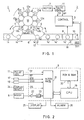
- the filling machine 1 includes a rotary filling unit 3, a loading unit 4, an unloading unit 5 and a belt conveyer 6, which are synchronously driven by a motor 7.
- the weight sorting machine 2 includes a weighing unit 8, a control unit 9, a take-out conveyer 10 and a pulse generator 11 also driven by a motor 7.
- the filling unit 3 includes eight filling stations or heads 12a, 12b, 12c, 12d, 12e, 12f, 12g and 12h, each having a bottle catching unit 13 for catching a bottle 14 to be filled and revolving it around a central axis and a filling nozzle 15 for injecting liquid product such as drink fed from a common source 16 into the bottle 14 during its revolution.
- the loading unit 4 is adapted to successively catch empty bottles 14 carried in line by the belt conveyer 6 and to hand over them one by one to the catching units 13 and the unloading unit 5 is adapted to receive filled bottles 14′ from the catching units 13 and to return them onto the belt conveyer 6.
- the unloading unit 5 is designed so as to receive a filled bottle from a specific catching unit as position A1 and return it onto the belt conveyer at position A2 at the same time as the same catching unit arriving at position A3 after 45 degree revolution.
- the belt conveyer 6 is adjacent at its end to the weighing unit 8 which may be a conventional conveyer-type electronic weigher, and hands over the filled bottles 14′ onto its weighing conveyer cradle.
- the weighing unit 8 weighs each filled bottle and provides a corresponding weight indicative signal to the control unit 9.
- the take-out conveyer 10 receives the weighed bottles 14′ from the weighing unit 8 to deliver them to a further process such as classification or sorting.
- the pulse generator 11 which may be of a rotary slit type, provides a timing pulse TP and an ario recognition pulse RP to the control unit 9 as described in detail later.
- a photoelectric sensor 17 is disposed for detecting each filled bottle on the conveyer 6 at position A2 to provide a first sense signal SS1 to the control unit 9 and another photoelectric sensor 18 is disposed for detecting the filled bottle 14′ just after it is weighed by the weiging unit 8 to provide a second sense signal SS2 also to the control unit 9.
- the control unit 9 includes a central processing unit (CPU) 19 which may be a microcomputer associated with a memory device 20 and the CPU 19 receives the above-mentioned pulse signals TP and RP and sense signals SS1 and SS2 through an interface device 21.
- the CPU 19 also receives the weight signal from the weighing unit 8 through an amplifier 22, an analog-to-digital (A/D) convertor 23 and the interface device 21.
- A/D analog-to-digital
- the CPU 19 of this inventive device can effect some improved operations such as (1) classifying measured weights of the bottles by each filling head and storing them in a random access memory (RAM) in the memory device 20, (2) calculating a mean value of the stored weights by each filling head, (3) sorting the measured weights corresponding to each filling head into predetermined classes and counting the number of bottles in 6 each class, and (4) counting the number of bottles sorted continuously into a predetermined defective class.
- RAM random access memory
- These data are temporarily stored in the RAM and selectively displayed by a display unit 25 in accordance with a display signal applied from a display selecting unit 2 such as a selector switch or keyboard unit.
- An alarm device 26 may be provided for generating an alarm signal when the number of defective bottles exceeds a predetermined value.
- the device of this invention has means for identifying the filling head which filled a specific bottle which is now weighed by the weighing unit 8.
- reference numbers 1, 2, ... 8 will be given to the filling heads 12a, 12b, ... 12h.
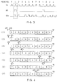
- the pulse generator 11 is adapted to successively generate eight timing pulses TP every revolution of the filling unit 3 and an origin recognition pulse RP every time the first filling head 12a comes to the reference position A3 of Figure 1.
- the memory device 20 includes a counter region and the TP pulses are counted by a C1-counter in this region.
- the C1-counter is adapted to reset its count C1 to "one" in response to each RP pulse.
- the count C1 represents the reference number of the filling head which is in position A3 and, therefore, which filled the bottle 14′ which is now at position A2 , as shown in Figure 3.
- This count is successively stored in a memory region M1 provided in the RAM of the memory device 20 as described below.
- the memory region M1 includes a plurality of memory locations arranged in line and has two address pointers AP1 and AP2 moving in response to the above-mentioned sense signals SS1 and SS2 to point the memory location to be written in and read out, respectively.
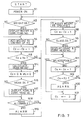
- Such a storage control operation of the memory region M1 is executed in accordance with programs as shown in the sub-routines given by Figures 5A and 5B.
- the sub-routine of Figure 5A is executed every time the timing pulse TP is generated and the sub-routine of Figure 5B is executed every time the second sense signal SS2 is generated, by interrputing a main routine which is previously stored in a read-only memory (ROM) of the memory device 20 and will be described later.
- ROM read-only memory
- step P2 the count of C1-counter if reset to "one" (step P2) and it is inquired whether the sense signal SS1 exists or not (step P3).
- step P3 the first address pointer AP1 is moved to the first memory location in the memory region M1 and the current C1-count "one" is written in this location as shown in Figure 4(2).
- the program returns to the main routine.
- the filling unit 3 rotates by 45 degrees and the bottle filled by the second filling head 12b is sensed at position A2
- another timing pulse is generated to interrupt the main routine.
- no pulse RP is generated and, therefore, the C1-count is stepped up to "two" (step P5). This count is written into the second memory location of M1-region since the address pointer AP1 is moved thereto in step P4.
- the memory location of M1-region moves rightwards one by one with the address pointer AP1 and the count of C1-counter is stepped up also one by one and written sequentially in the pointed location.
- no sense signal SS1 occurs and the step P4 is omitted, so that no count is written in this memory region though it is increased by one in step S6. This results in a dropout of the count corresponding to the number of accidental filling head from the sequential memory array.
- Figure 4(3) shows such a memory array when the first bottle filled by the filling head 12a gets on the weighing unit 8 and the fourth bottle is sensed by the first sensor 17, while the third filling head 12c was accidentally vacant and no corresponding sense signal SS1 was given as shown in Figure 3.
- a sense signal SS2 is provided to the control unit 9 to interrupt the main routine and start the sub-routine as shown in Figure 5B.
- the A/D convertor 23 is first actuated (step Q1) and its digital output indicative of the weight of the first bottle is read in CPU 19 (step Q2).
- the second address pointer AP2 is moved to the first memory location and the content of this location, namely, "one" is read out (step Q3).
- This count is supplied to another memory region M2 in the RAM of the memory device 20 together with the weight read in the CPU 19 and the weight is stored in a memory location of the region M2 specified by this count (step Q4) as described below with reference to Figure 6.
- the memory array of M1 region becomes as shown in Figure 4(4) when the second bottle arrives at the weighing unit 8 and the fifth bottle is sensed by the first sensor 17.
- the second address pointer AP2 moves rightwards one by one and the pointed memory content is read out and combined with the current weight signal every time the filled bottle is sensed by the second sensor 18.
- no signal SS2 is given to avoid execution of the sub-routine of Figure 5B.
- the storage procedure in the memory region M1 progresses similarly as resetting the count C1 to "one" in response to each RP pulse and stepping both pointers AP1 and AP2 rightwards and the first pointer AP1 finally reaches the rightmost location as shown in Figure 4(5).
- the pointer AP1 returns to the leftmost or first location and the content of this location, namely "one" at this time, is substituted with the current C1-count, namely "seven" at this time, as shown in Figure 4(6).
- the second pointer AP2 also resurns to the first location from the rightmost location.
- the first pointer AP1 When the bottle loading operation is interrupted, for example, at the sixth filling head, the first pointer AP1 will no longer move after the last bottle filled by this head is sensed by the first sensor 17 though the second pointer AP2 continues its movement. Accordingly, the second pointer AP2 will finally reach the location of the first pointer AP1, which stores "six" in this case, as shown in Figure 4(6) and no further change will occur in the memory region M1.
- the memory region M1 of Figure 4 has twelve memory locations, it is understood that the number of such locations can be reduced to "four" in this example, since the number of memory locations existing between both pointers AP1 and AP2 is always "four" or less and no more location is needed for the above-mentioned operation. This allowable smallest number is equal to the number of bottles which can exist between both sensors 17 and 18 in Figure 1.
- the memory device 20 includes seven memory regions M2 to M8 each having eight memory locations corresponding to respective filling heads 12a to 12h, as shown tabularly in Figure 6.
- head numbers 1 to 8 correspond to C1-counts read out from the above-mentioned memory region M1 in step Q3
- the region M2 is adapted to store the weight signal from the weighing unit 8 in its corresponding memory location in step Q4 as described above.
- the third region M3 is adapted to store a cumulative sum of the measured weights and the fourth region M4 is adapted to store a mean value thereof, by each filling head.
- the fifth, sixth and seventh regions M5, M6 and M7 are adapted to store the number of bottles classified into three predetermined classes by weight and the last region M8 is adapted to store the number of bottles whose wheights are judged as unacceptable under a predetermined condition.
- These stored data can be selectively displayed by the display unit 25 in response to a display signal DS from the display selecting unit 24.
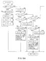
- Such storage and display operations are executed by CPU 19 in accordance with the main routine as shown in Figure 7.
- step N1 the operator first puts on the power switch to start the weight sorting machine 2 and then operates the display selecting unit 24 to specify the items of data stored in the memory regions of Figure 6 and provide corresponding display signals DS (step N1).
- step N2 the operator first puts on the power switch to start the weight sorting machine 2 and then operates the display selecting unit 24 to specify the items of data stored in the memory regions of Figure 6 and provide corresponding display signals DS (step N1).
- step N2 the next step, it is inquired whelther a weight display signal exist or not (step N2) and, if YES, the measured weight is read out from the memory region M2 and displayed with the corresponding filling head number (step N3). If not, no weight is displayed.
- the measured weight read out from the memory region M2 is stored in a corresponding memory location of the memory region M3, which is now empty (step N4). Thereafter, the counter C2 is stepped up to "one" (step N5) and it is inquired whether this count has reached a value K1 or not (step N6).
- K1 is a predetermined value corresponding to the number of weights to be accumulated in the memory region M3 for calculating a mean value thereof. As the answer is NO in this case, this weight is classified into one of the predetermined classes such as of "low”, “medium” and “high” weights, as shown in Figure 6 (step N7) and the counter C3 of the corresponding class is stepped up to "one” (step N8).
- step 9 it is inquired whether any class display signal exists or not (step 9) and, if YES, the stored C3-count is displayed with the specified class and filling head number (step N10). If not, no display is effected thereabout. Then, the weight value is compared with a predetermined allowable range and it is inquired whether it is acceptable or not (step N11). If not (unacceptable), the counter C4 is stepped up to "one" in this case (step N12) and it is then inquired whether this count has reached a specific value K2 or not (step N13). K2 is a predetermined extreme number of unacceptable bottles or rejects which is to be alarmed. If the answer is NO, the program returns to step N2 and the same steps are repeated.
- step N4 the successive measured weights are accumulated in each memory location of the memory region M3 (step N4) and the number of these weights is counted by the counter C2 (step N5).
- step N6 the mean weight by each filling head is calculated by dividing the content of each location of M3 by K1 (step N14) and the result is stored in a corresponding memory location of the memory region M4 (Fig. 6).
- the counter C2 is reset to "zero" and the corresponding memory location of M2 is cleared (step N15).
- step N16 it is inquired whether a mean display signal exists or not (step N16) and, if YES, the calculated mean weight is displayed with the corresponding filling head number (step N17). If not, this display is not effected. Thereafter, the mean weight is compared with a predetermined allowable range and it is inquired whether it is allowable or not (step N18). If allowable, the process continues to step N7 but, if not, an alarm signal is generated from the alarm device 26 (step N19).
- step N20 When the count C4 reaches the value K2 (step N13) during the progress of operation, an alarm is generated (step N20) and the counter C4 is reset to "zero" (step N21). Such resetting of the count C4 is also effected when the weight is acceptable in step N11. Therefore, it is understood that the alarm is only given when K2-number of rejects have appeared sequentially without interruption.
- the filling unit 3 of the bottle filling machine of Figure 1 is constructed as of serial quintuple batch type instead of rotary type.
- This filling unit 3 includes five filling stations or heads 12a, 12b, 12c, 12d and 12e arranged serially and is adapted to catch five empty containers or bottles 14 which are loaded by a suitable device such as belt conveyer and to fill then with product concurrently through five nozzles (not shown).
- a suitable device such as belt conveyer and to fill then with product concurrently through five nozzles (not shown).
- the five filled bottles 14′ are concurrently transferred in arrow direction onto the belt conveyer 6 by a suitable unloading device (not shown) and conveyed rightwards as they are to the weighing unit 8.
- the filled bottles are sequentially detected by the photoelectric sensors 17 and 18 during movement and weighing, thereby producing first and second sense signals SS1 and SS2, respectively, as in the embodiment of Figure 1.
- the pulse geneator 11 of this embodiment is adapted to generate independent clock pulses CP and also provide an origin recognition pulse RP every time the unloading device of the filling unit 3 is actuated, as shown in Figure 9.
- the first sense signal SS1 corresponding to the bottle filled by the first filling head 12a is produced after a fixed time t1 from this pulse RP and, thereafter, four sense signals SS1 corresponding to second to fifth filling heads are sequentialy produced at time intervals t2 which correspond to the head interval. If a filled bottle drops out from a certain (e.g., the third) filling head, a corresponding SS1 pulse drops out as shown by SS1(2) of Figure 9.
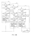
- the control unit 9 includes a C5-counter for counting the sense signals SS1 and a t-counter for counting the clock pulses CP to measure the time intervals t1 and t2. While the control unit 9 of this invention is similar to that of the embodiment of Figure 1 in both structure and operation, it only differs in counting the clock pulses CP instead of the timing pulses TP. The operation will be described below with reference to Figure 10.
- the sub-routine of Figure 10 is executed by interrupting the main routine of Figure 7 in response to each clock pulse CP.
- a recognition pulse flag RPF is used in this operation. This flag is defined as a binary state of a RPF register included in CPU of the control unit 9 and assumed to be in a low level or "0" state at first. It is first inquired whether the RPF is in a high level or "1" state or not (step R1) and, as the answer is NO, it is then inquired whether the origin recognition pulse RP is input or not (step R2). If no RP input exists, the program returns to the main routine. However, if it exists, RPF is set to "1" (step R3), C5-counter is reset to "0" (step R4), t-counter is reset to "0” (step R5) and the program returns to the main routine.
- step R1 As the answer of step R1 is YES in the next cycle, the count of t-counter is stepped up to "1" (step R6) and it is inquired whether the count of C5-counter is "0" or not (step R7). As the answer is YES, it is inquired whether the t-count corresponds to the time t1 or not (step R8). As the answer is NO at first, it is inquired whether the sense signal SS1 is received or not (step R9). As the answer is NO until the first filled bottle 14′ reaches the sensor 17, the program returns to the main routine and the same operation is repeated to count up the CP pulses every step R6.
- the first filled bottle 14′ is sensed by the sensor 17 and a signal SS1 is provided (step R9).
- the C5-count is then stepped up to "1" (step R10) and, in the same manner as the embodiment of Figure 1, the address pointer AP1 of the memory region M1 is moved to the first memory location and the C5-count "1" is written in this location (step R11).
- the program returns to the main routine. If the first bottle has been lost, the t-count reaches the count corresponding to the predetermined time t1 before the SS1 signal (step R8). Accordingly, the C5-count is stepped up to "1" (step R12) and the program returns to the main routine. Thus, the lost bottle is counted but the count is not written in the memory region M1.
- step R7 the program progresses from step R7 to R13 in the next cycle and it is inquired whether C5-count is "1" or not (step R13). As the answer is YES, it is further inquired whether the t-count corresponds to time t1+t2 or not (step R14) and the same operation is repeated until this answer becomes YES.
- steps R15 to R17 which are similar to steps R9 to R11 are executed to step up the C5-count to "2" and write it in the second memory location of the memory region M1.
- step R18 If the second bottle has been lost, the count becomes "2" (step R18) but is not written in M1 region. Thereafter, similar operations as shown in dashed blocks A, B and C in Figure 10 are executed in the same manner in connection with the third to fifth bottles and corresponding filling head numbers 3, 4 and 5 are sequentially written in M1 region. Finally, the RPF flag is reset to "0" (step R19) and the program returns to the main routine.
- the filling head numbers written in the memory region M1 are read out in accordance with the interrupt routine of Figure 5B which is responsive to the second sense wignal SS2, in the substantially same manner as the embodiment of Figure 1. It is obvious that the measured weight value and the filling head number which are read out in response to the signal SS2 correctly correspond to each other as in the case of the embodiment of Figure 1, since the writing and reading systems of the memory locations of M1 region are unchanged at all. It is, of course, possible to effect collection, calculation and display of various data and to alarm occurrence of abnormal condition as in the embodiment of Figure 1, though no further description is made thereabout.
Landscapes
- Basic Packing Technique (AREA)
- Sorting Of Articles (AREA)
Applications Claiming Priority (2)
| Application Number | Priority Date | Filing Date | Title |
|---|---|---|---|
| JP103757/88 | 1988-04-26 | ||
| JP63103757A JPH01274883A (ja) | 1988-04-26 | 1988-04-26 | 自動重量選別機 |
Publications (2)
| Publication Number | Publication Date |
|---|---|
| EP0339943A2 true EP0339943A2 (de) | 1989-11-02 |
| EP0339943A3 EP0339943A3 (de) | 1992-01-08 |
Family
ID=14362408
Family Applications (1)
| Application Number | Title | Priority Date | Filing Date |
|---|---|---|---|
| EP19890304123 Withdrawn EP0339943A3 (de) | 1988-04-26 | 1989-04-25 | Automatische Sortiermaschine nach Gewicht |
Country Status (3)
| Country | Link |
|---|---|
| US (1) | US4972882A (de) |
| EP (1) | EP0339943A3 (de) |
| JP (1) | JPH01274883A (de) |
Cited By (5)
| Publication number | Priority date | Publication date | Assignee | Title |
|---|---|---|---|---|
| AT406740B (de) * | 1996-07-02 | 2000-08-25 | Wintersteiger Gmbh & Co | Vorrichtung zum befüllen von saatgutmagazinen mit samenkörnern ausgewählter zuchtpflanzen |
| CN101413821B (zh) * | 2007-10-16 | 2011-11-30 | 上海恒谊制药设备有限公司 | 一种快速的在线称重检测装置 |
| CN109290223A (zh) * | 2017-07-25 | 2019-02-01 | 广州宁基智能系统有限公司 | 一种五金件分拣系统及其应用 |
| CN111871852A (zh) * | 2020-06-19 | 2020-11-03 | 嘉里粮油(防城港)有限公司 | 一种无手把瓶子剔除方法、贴标机及存储介质 |
| CN115591801A (zh) * | 2022-09-05 | 2023-01-13 | 合肥友高物联网标识设备有限公司(Cn) | 一种多码垛工位混合输出线的产品分拣控制方法 |
Families Citing this family (15)
| Publication number | Priority date | Publication date | Assignee | Title |
|---|---|---|---|---|
| DE3824727A1 (de) * | 1988-07-21 | 1990-01-25 | Henkel Kgaa | Anlage zur dosierung und mischung unterschiedlicher stoffe, insbesondere zur erzeugung von parfuems |
| US5109936A (en) * | 1989-06-28 | 1992-05-05 | Cahin Systems Corporation | Dynamic weight control system |
| DE3938220A1 (de) * | 1989-11-17 | 1991-05-23 | Benz & Hilgers Gmbh | Verfahren und vorrichtung zum verpacken von pastoesen produkten, wie suppenpasten, margarine, butter oder dgl. in form von paeckchen, wuerfeln oder dgl. |
| JP2972967B2 (ja) * | 1991-02-26 | 1999-11-08 | アンリツ株式会社 | 計量装置 |
| DE4117287A1 (de) * | 1991-05-27 | 1992-12-03 | Seitz Enzinger Noll Masch | Verfahren zum fuellen von flaschen, dosen o. dgl. behaelter sowie fuellmaschine zum durchfuehren dieses verfahrens |
| JPH0647300A (ja) * | 1992-07-28 | 1994-02-22 | Kobe Steel Ltd | 堅型衝撃式破砕機 |
| DE19513103A1 (de) * | 1995-04-07 | 1996-10-10 | Buehler Optima Maschf | Vorrichtung und Verfahren zum Befüllen von Behältern |
| NL1006685C2 (nl) * | 1997-07-30 | 1999-02-02 | Gerritse Beheer Bv | Inrichting voor het gedoseerd afgeven van een aantal verschillende vloeibare of pasteuze massa's. |
| JP4452904B2 (ja) * | 1999-07-27 | 2010-04-21 | 澁谷工業株式会社 | ウエイトフィラ |
| DE102005031794A1 (de) * | 2005-07-07 | 2007-01-25 | Khs Ag | Verfahren und Vorrichtung zum Überprüfen einer Behälterbehandlungsanlage |
| TWI407763B (zh) * | 2008-05-13 | 2013-09-01 | Htc Corp | 電子裝置、接通與拒絕通話方法及數位資料儲存媒體 |
| US10036664B2 (en) | 2015-04-03 | 2018-07-31 | Bot Llc | Method and apparatus for sorting and combining fragile and varying density pieces |
| CN108636822A (zh) * | 2018-06-27 | 2018-10-12 | 惠州市国鹏印刷股份有限公司 | 用于精品盒的不良品剔除装置 |
| CN112551135B (zh) * | 2020-11-20 | 2022-12-13 | 苏州西斯派克检测科技有限公司 | 一种吹瓶机设备的同步测量系统及方法 |
| CN113357976A (zh) * | 2021-06-01 | 2021-09-07 | 南京海道普数据技术有限公司 | 一种工件成组生产线自动选配系统 |
Family Cites Families (12)
| Publication number | Priority date | Publication date | Assignee | Title |
|---|---|---|---|---|
| US3017992A (en) * | 1958-03-24 | 1962-01-23 | Bartelt Engineering Co Inc | Machine for classifying packages according to weight |
| US3073400A (en) * | 1959-07-16 | 1963-01-15 | Fr Hesser Maschinenfabrik Ag F | Volumetric filling machine |
| US3368593A (en) * | 1964-10-09 | 1968-02-13 | Industrial Nucleonics Corp | Originating filler identification system |
| US3484813A (en) * | 1967-11-07 | 1969-12-16 | Nat Biscuit Co | Container filling apparatus with automatic checkweigher |
| DE3113421C2 (de) * | 1981-04-03 | 1984-05-10 | Haver & Boecker, 4740 Oelde | "Rotierende Füllmaschine mit einer im Abtransportweg der gefüllten Säcke vorgesehenen Kontrollwaage" |
| DE3150183C1 (de) * | 1981-12-18 | 1983-06-01 | Kronseder Maschf Krones | Gefäßfüllmaschine |
| US4513796A (en) * | 1982-06-24 | 1985-04-30 | Baxter Travenol Laboratories, Inc. | High speed bulk compounder |
| DE3425082C2 (de) * | 1984-07-07 | 1986-05-15 | Haver & Boecker, 4740 Oelde | Füllmaschine mit mehreren Füllstutzen und einem Förderer zum Abtransport der gefüllten Säcke dem eine Kontrollwaage zugeordnet ist |
| US4582102A (en) * | 1984-08-27 | 1986-04-15 | Risser James A | Means for electronically comparing the extent of fill in containers with a preset extent |
| US4639263A (en) * | 1985-07-16 | 1987-01-27 | Emhart Industries, Inc. | Glassware forming production monitor |
| US4696329A (en) * | 1986-06-09 | 1987-09-29 | Mateer Burt Co., Inc. | Feedback control for automatic filling machine |
| JPH0762631B2 (ja) * | 1986-11-15 | 1995-07-05 | 株式会社石田衝器製作所 | 組合せ計量装置 |
-
1988
- 1988-04-26 JP JP63103757A patent/JPH01274883A/ja active Pending
-
1989
- 1989-04-04 US US07/333,551 patent/US4972882A/en not_active Expired - Fee Related
- 1989-04-25 EP EP19890304123 patent/EP0339943A3/de not_active Withdrawn
Cited By (6)
| Publication number | Priority date | Publication date | Assignee | Title |
|---|---|---|---|---|
| AT406740B (de) * | 1996-07-02 | 2000-08-25 | Wintersteiger Gmbh & Co | Vorrichtung zum befüllen von saatgutmagazinen mit samenkörnern ausgewählter zuchtpflanzen |
| CN101413821B (zh) * | 2007-10-16 | 2011-11-30 | 上海恒谊制药设备有限公司 | 一种快速的在线称重检测装置 |
| CN109290223A (zh) * | 2017-07-25 | 2019-02-01 | 广州宁基智能系统有限公司 | 一种五金件分拣系统及其应用 |
| CN109290223B (zh) * | 2017-07-25 | 2021-03-09 | 广州宁基智能系统有限公司 | 一种五金分拣系统的应用 |
| CN111871852A (zh) * | 2020-06-19 | 2020-11-03 | 嘉里粮油(防城港)有限公司 | 一种无手把瓶子剔除方法、贴标机及存储介质 |
| CN115591801A (zh) * | 2022-09-05 | 2023-01-13 | 合肥友高物联网标识设备有限公司(Cn) | 一种多码垛工位混合输出线的产品分拣控制方法 |
Also Published As
| Publication number | Publication date |
|---|---|
| JPH01274883A (ja) | 1989-11-02 |
| EP0339943A3 (de) | 1992-01-08 |
| US4972882A (en) | 1990-11-27 |
Similar Documents
| Publication | Publication Date | Title |
|---|---|---|
| EP0339943A2 (de) | Automatische Sortiermaschine nach Gewicht | |
| US4819176A (en) | Process control and data collection system | |
| US3939928A (en) | Weighing method and apparatus | |
| US3974888A (en) | Method of weighing and apparatus therefor | |
| EP0348077A1 (de) | Vorrichtung zum automatischen Einfüllen und Verpacken von Produktmengen bestimmten Gewichtes in Behälter | |
| US3868643A (en) | Conveyor memory system | |
| JP4758037B2 (ja) | 重量選別機及び重量選別機用データ収集装置 | |
| CN109848069B (zh) | 一种物流配送货物全自动分拣包装系统及其方法 | |
| EP0028527A1 (de) | System und Verfahren zum Sortieren von Gegenständen nach bestimmten physikalischen Eigenschaften | |
| US4645019A (en) | Method of weighting and counting | |
| US4580226A (en) | Random sampling system | |
| EP0074269B1 (de) | Verfahren zum Zählen von Teilen | |
| CA1274294A (en) | Metal detector testing process and apparatus | |
| US4091449A (en) | Computing scale system | |
| JP4101086B2 (ja) | 返品書籍の仕分け設備 | |
| JP2017132513A (ja) | 計量包装検査システム | |
| JP2004258932A (ja) | 返品書籍の検品方法 | |
| JP3494181B2 (ja) | 製造システム | |
| SU1471083A1 (ru) | Устройство дл определени количества объектов равной массы | |
| JPH0531464A (ja) | 重量選別機 | |
| JP3355427B2 (ja) | 物品検査装置 | |
| JPH0339620A (ja) | 組合せ計量装置 | |
| JPH0687030B2 (ja) | 重量選別装置 | |
| US3024906A (en) | Automatic digital sorting system | |
| JPH0236631Y2 (de) |
Legal Events
| Date | Code | Title | Description |
|---|---|---|---|
| PUAI | Public reference made under article 153(3) epc to a published international application that has entered the european phase |
Free format text: ORIGINAL CODE: 0009012 |
|
| AK | Designated contracting states |
Kind code of ref document: A2 Designated state(s): DE FR GB |
|
| PUAL | Search report despatched |
Free format text: ORIGINAL CODE: 0009013 |
|
| AK | Designated contracting states |
Kind code of ref document: A3 Designated state(s): DE FR GB |
|
| 17P | Request for examination filed |
Effective date: 19920131 |
|
| STAA | Information on the status of an ep patent application or granted ep patent |
Free format text: STATUS: THE APPLICATION HAS BEEN WITHDRAWN |
|
| 18W | Application withdrawn |
Withdrawal date: 19930129 |