EP0339032B1 - Beschichtungsvorrichtung und -verfahren - Google Patents
Beschichtungsvorrichtung und -verfahren Download PDFInfo
- Publication number
- EP0339032B1 EP0339032B1 EP88900332A EP88900332A EP0339032B1 EP 0339032 B1 EP0339032 B1 EP 0339032B1 EP 88900332 A EP88900332 A EP 88900332A EP 88900332 A EP88900332 A EP 88900332A EP 0339032 B1 EP0339032 B1 EP 0339032B1
- Authority
- EP
- European Patent Office
- Prior art keywords
- web
- backing member
- coating
- blade
- belt
- Prior art date
- Legal status (The legal status is an assumption and is not a legal conclusion. Google has not performed a legal analysis and makes no representation as to the accuracy of the status listed.)
- Expired - Lifetime
Links
- 238000000576 coating method Methods 0.000 title claims abstract description 108
- 239000011248 coating agent Substances 0.000 title claims abstract description 107
- 238000000034 method Methods 0.000 title claims description 12
- 239000000463 material Substances 0.000 claims abstract description 36
- 230000002939 deleterious effect Effects 0.000 claims abstract description 13
- 230000002401 inhibitory effect Effects 0.000 claims abstract description 13
- 238000011144 upstream manufacturing Methods 0.000 claims description 8
- 238000003825 pressing Methods 0.000 claims description 2
- 239000007788 liquid Substances 0.000 description 2
- 238000005406 washing Methods 0.000 description 2
- 238000010521 absorption reaction Methods 0.000 description 1
- 239000000654 additive Substances 0.000 description 1
- 230000000996 additive effect Effects 0.000 description 1
- 238000011109 contamination Methods 0.000 description 1
- 230000007547 defect Effects 0.000 description 1
- 238000010438 heat treatment Methods 0.000 description 1
- 230000005764 inhibitory process Effects 0.000 description 1
- 239000002245 particle Substances 0.000 description 1
- 238000004513 sizing Methods 0.000 description 1
- XLYOFNOQVPJJNP-UHFFFAOYSA-N water Substances O XLYOFNOQVPJJNP-UHFFFAOYSA-N 0.000 description 1
Images

Classifications
-
- D—TEXTILES; PAPER
- D21—PAPER-MAKING; PRODUCTION OF CELLULOSE
- D21H—PULP COMPOSITIONS; PREPARATION THEREOF NOT COVERED BY SUBCLASSES D21C OR D21D; IMPREGNATING OR COATING OF PAPER; TREATMENT OF FINISHED PAPER NOT COVERED BY CLASS B31 OR SUBCLASS D21G; PAPER NOT OTHERWISE PROVIDED FOR
- D21H23/00—Processes or apparatus for adding material to the pulp or to the paper
- D21H23/02—Processes or apparatus for adding material to the pulp or to the paper characterised by the manner in which substances are added
- D21H23/22—Addition to the formed paper
- D21H23/32—Addition to the formed paper by contacting paper with an excess of material, e.g. from a reservoir or in a manner necessitating removal of applied excess material from the paper
- D21H23/34—Knife or blade type coaters
- D21H23/36—Knife or blade forming part of the fluid reservoir, e.g. puddle-type trailing blade or short-dwell coaters
-
- B—PERFORMING OPERATIONS; TRANSPORTING
- B05—SPRAYING OR ATOMISING IN GENERAL; APPLYING FLUENT MATERIALS TO SURFACES, IN GENERAL
- B05C—APPARATUS FOR APPLYING FLUENT MATERIALS TO SURFACES, IN GENERAL
- B05C9/00—Apparatus or plant for applying liquid or other fluent material to surfaces by means not covered by any preceding group, or in which the means of applying the liquid or other fluent material is not important
- B05C9/08—Apparatus or plant for applying liquid or other fluent material to surfaces by means not covered by any preceding group, or in which the means of applying the liquid or other fluent material is not important for applying liquid or other fluent material and performing an auxiliary operation
Definitions
- This invention relates to a short dwell coating apparatus and a method for applying a coating onto a surface of a moving web. More particularly, this invention relates to a short dwell coating apparatus for coating a surface of a paper web.
- the short dwell coater enables coating material under hydraulic pressure to be applied to a limited area of a moving web with a flexible blade defining the downstream edge of such area. Any excess coating material flows from such area away from the blade in a direction opposite to the direction of movement of the web.
- the short time that the coating material is disposed in contact with the web prior to removal of excess coating material by the blade Such short time period inhibits absorption of the coating material throughout the web.
- a coating apparatus of the aforementioned type and according to the preamble of claim 1 is described in GB-A-2106015.
- This known coating apparatus includes a backing member and a short dwell coating blade disposed adjacent to the backing member.
- a method according to the preamble of claim 10 is also known from GB-A-2106015.
- the short dwell coater presents many advantages over the prior art coating methods.
- the web is moving in the region of 15.2 or more m/s (3,000 or more feet per minute) past the short dwell coater, there is a tendency for an air pocket to develop between the backing roll and the web upstream relative to the short dwell coater.
- the aforementioned air pocket when coating at high speeds, has sometimes resulted in web breakage and streaking.
- any particles of contamination on the surface of the web or in the short dwell coating pond to become lodged against the blade thereby causing marking of the surface of the coating and sheet breaks.
- the primary objective of the present invention is the provision of a short dwell coating apparatus that overcomes the aforementioned problems associated with the prior art coating apparatus and that provides a significant contribution to the art of coating moving webs.
- the apparatus of the invention is characterized by the features claimed in the characterizing part of claim 1 and the method of the invention is characterized by the features of claim 10.
- Advantageous embodiments of the invention are claimed in the subclaims.
- the present invention overcomes the aforementioned problems by the provision of a backing roll having a perforate surface with a permeable belt disposed between the perforate surface and the web.
- a vacuum is applied to the backing member, the web is drawn into close conformity with the belt thereby inhibiting the generation of an air pocket between the web and the backing member and preventing streaking, lodging or hangup of deleterious material adjacent to the blade.
- a feature of the present invention is the provision of a coating apparatus including a backing member defining a perforate surface.
- the coating apparatus further includes a permeable belt extending around the backing member and disposed between the web and the backing member such that when a source of partial vacuum is connected to the backing member, air flows through the permeable belt and the perforate surface for drawing the web into close conformity with the belt so that the belt and web move together and in the same direction for inhibiting the buildup of deleterious material adjacent to the coating blade.
- the permeable means is a wire mesh belt which includes a first layer disposed contiguous relative to the perforate surface and a second layer disposed contiguous relative to the first layer with the second layer being disposed contiguous relative to the mesh of the first layer such that during coating of the web, vacuum applied through the perforate surface is evenly distributed by means of the first layer and the second layer inhibits marking of the contiguous surface of the web.
- the apparatus includes a backing member which defines a perforate surface such that when the member is connected to a source of partial vacuum, the web is drawn towards the perforate surface of the member.
- a coating blade is disposed adjacent to the backing member such that the blade urges the web towards the perforate surface.
- a permeable means extends around the backing member with the permeable means being disposed between the web and the backing member such that when the source of partial vacuum is connected to the backing member, air flows through the permeable means and the perforate surface for drawing the web into close conformity with the permeable means so that the permeable means and the web move together in the same direction for inhibiting hangup of deleterious material adjacent to the blade that would otherwise cause sheet breaks and marking of the coating applied to the surface of the web by the blade.
- the backing roll Due to the small area of contact of the sheet with the backing roll, the backing roll usually travels faster than the sheet. There is normally a layer of air between the sheet and the backing roll, so there is backing roll slippage. With a vacuum in the backing member, sheet contact with the belt is insured, eliminating slippage. The vacuum-held sheet is pulled past the blade. Some sheet defects will also be pulled past the blade resulting in better runnability, or fewer sheet breaks.
- the backing member is a rotatable suction roll.
- the backing member is a vacuum box.
- the rotatable suction roll also includes a rotatable outer shell which defines the perforate surface.
- the vacuum box includes a wall disposed contiguous relative to the permeable means, the wall defining the perforate surface.
- the coating blade is a short dwell coating head or a conventional coater head with an applicator roll.
- the permeable means is a continuous belt.
- the belt is a wire mesh having a first layer disposed contiguous relative to the perforate surface.
- a second layer of the belt is disposed contiguous relative to the first layer with the second layer being disposed contiguous relative to the web.
- the second layer is of a finer mesh relative to the mesh of the first layer such that during coating of the web, the vacuum applied through the perforate surface is evenly distributed by means of the first layer.
- the second layer inhibits marking of the contiguous surface of the web.
- the coating apparatus of the present invention also inhibits the generation of an air pocket between the backing member and web upstream relative to the coating blade.
- the present invention provides a method of applying a coating onto the surface of a moving web, such method comprising the step of connecting a backing member to a source of partial vacuum such that the web is drawn towards a perforate surface defined by the backing member.
- the next step includes pressing the web towards the perforate surface by means of a short dwell coating head or a conventional coater disposed adjacent to the backing member.
- a third step includes interposing a permeable belt between the perforate surface of the backing member and the web such that when the partial vacuum is applied through the perforate surface and the permeable belt, the web is drawn into close conformity with the belt for firstly, inhibiting the buildup or hangup of deleterious material adjacent to the blade, and secondly for inhibiting the generation of an air pocket between the backing member and the web upstream relative to the blade.
- the present invention includes the application of any coating material or sizing composition or additive to the surface of any moving web.
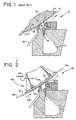
- Figure 1 is a fragmentary sectional view of a prior art short dwell coater generally designated 10.
- the coater 10 cooperates with a backing member 12 such that a web W is disposed and moves between the backing member 12 and the coater 10.
- Pressurized coating material is disposed within a header 14 defined by the coater 10.
- the coating material flows as indicated by the arrow 16 into a short dwell coating pond 18 so that a relatively small area of the moving web W is contacted by the coating material as the web W travels past the coating pond 18.
- a flexible coating blade 20 urges the web W against the backing member 12 such that the coating blade 20 defines an edge of the coating pond 18 so that excess coating material removed from the web W by the coating blade 20 is urged away from the web W as indicated by the arrow 22 in a direction opposite to the direction of movement of the web W as indicated by the arrow 24.
- Such excess coating material is returned through a coating return 26 so that such coating material may be filtered and re-pressurized.
- FIG. 2 is a fragmentary sectional view of a coating apparatus according to the present invention.
- the coating apparatus generally designated 32 applies a coating 30a onto a surface 34 of a moving web Wa.
- the apparatus 32 includes a backing member generally designated 12a which defines a perforate surface 36 such that when the member 12a is connected to a source of partial vacuum 38, the web Wa is drawn toward the perforate surface 36 of the member 12a.
- a coating blade 20a is disposed adjacent to the backing member 12a such that the blade 20a urges the web Wa towards the perforate surface 36.
- a permeable means generally designated 40 extends around the backing member 12a.
- the permeable means 40 is disposed between the web Wa and the backing member 12a such that when the source of partial vacuum 38 is connected to the backing member 12a, air flows through the permeable means 40 and the perforate surface 36 for drawing the web Wa into close conformity with the permeable means 40 so that the permeable means 40 and the web Wa move together and in the same direction as indicated by the arrow 24a for inhibiting the buildup of deleterious material adjacent to the blade 20a that would otherwise remain adjacent to the blade 20a causing marking of the coating 30a applied to the surface 34 of the web Wa by the blade 20a.
- the backing member 12a is a rotatable suction roll.
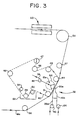
- FIG 3 is a side-elevational view of the coating apparatus shown in figure 2 and shows the backing member 12a as a rotatable suction roll which is connected to the source of partial vacuum 38 as indicated by the vacuum pump 42.
- the permeable means 40 extends around a plurality of rolls 44, 45, 461, 47, 48, 49, 50 and 51.
- Roll 47 is adjustable such that the tension of the permeable means 40 may be adjusted to the required optimum coating capability of the apparatus.
- Roll 49 is immersed in a washing tank 52 filled with washing liquid for removing cleansing material applied by a shower 54 disposed between rolls 48 and 49.
- the permeable means 40 extends away from the tank 52 and around roll 50 which is a suction roll and thereafter extends around roll 51.
- the web Wa extends around a plurality of rolls of which rolls 56, 51, 44, 57 and 57 are shown in figure 3. During passage between rolls 51 and 44, the web Wa is in contiguous relationship relative to the permeable means 40 such that the web Wa is disposed between the permeable means 40 and the coating blade 20a of the coating apparatus 32.
- the arrangement of the present invention enables on-line coating of the web Wa because such coating material may be applied to the web Wa at Web speeds in excess of 15.2 m/s (3,000 feet per minute).
- an infrared heating device generally designated 60 is used to dry the coated web.
- the short dwell coater 10a includes a pump 62 connected to the coating return line 26a such that excess coating material may be returned to the short dwell coater 10a.
- a second pump 64 feeds coating material to the short dwell coater 10a.
- the rotatable suction roll 12a includes a rotatable outer shell 66 which defines the perforate surface 36.
- the coating blade 20a is a short dwell coating blade and the permeable means 40 is a continuous belt.
- FIG 4 is a similar view to that shown in figure 3 but shows the rotatable suction roll 21a replaced by a vacuum box generally designated 12b.
- the vacuum box 12b includes a wall 68 which is disposed contiguous relative to the permeable means 40b.
- the wall 68 defines the perforate surface 36b.
- FIG. 5 is a sectional view of the permeable means 40.
- the permeable means 40 as shown in figure 5 is a continuous wire mesh belt which includes a first layer 70 disposed contiguous relative to the first layer 70.
- the second layer 72 is disposed contiguous relative to the web Wa or Wb with the second layer 72 being of a finer mesh relative to the mesh of the first layer 70 such that during coating of the web, vacuum applied through the perforate surface is evenly distributed by the first layer 70 and the second layer 72 inhibits marking of the contiguous surface of the web.
- the rotatable suction roll 12a is connected to a source of partial vacuum 38 such that the web Wa is drawn towards the perforate surface 36 defined by the rotatable outer shell 66.
- the web Wa is pressed towards the perforate surface 36 by means of the short dwell coating blade 20a disposed adjacent to the backing member 12a.
- the continuous belt 40 is interposed between the perforate surface 36 and the web Wa such that when the partial vacuum is applied to the perforate surface 36 and the permeable belt 40 the web Wa is drawn into close conformity with the belt 40 for firstly inhibiting the buildup of deleterious material adjacent to the blade 20a and secondly for inhibiting the generation of any air pocket, between the backing member 12a and the web Wa upstream relative to the blade 20a.
- a wire mesh belt having a first and second layer 70 and 72 respectively enables even distribution by means of the first layer 70 of the vacuum applied to the web Wa.
- the finer mesh second layer 72 avoids any possibility of marking the uncoated surface of the web Wa during passage past the backing member 12a.
- the present invention enables the continuous coating of a web at high speed without the associated problem of buildup of deleterious material adjacent to the coating blade.
- the web is caused to move at the same speed and in the same direction as the permeable means so that any deleterious material disposed within the coating pond adjacent to the coating blade tends to be dragged past the coating blade rather than lodging adjacent thereto.
- the provision of a vacuum through the backing member the generation of an air pocket with associated web breakage is inhibited.
Landscapes
- Coating Apparatus (AREA)
- Application Of Or Painting With Fluid Materials (AREA)
Claims (10)
dadurch gekennzeichnet, daß das Teil (12a; 12b) eine perforierte Oberfläche (36; 36b) aufweist, so daß, wenn das Teil (12a; 12b) mit einer Teilvakuumquelle (38;) verbunden wird, die Bahn an die perforierte Oberfläche (36; 36b) des Teils gesaugt wird, wobei die Klinge (20a;) die Bahn gegen die perforierte Oberfläche (36; 36b) drängt, und
daß sich weiter eine durchlässige Einrichtung (40; 40b) um das Stützteil (12a; 12b) erstreckt, wobei die Einrichtung (40; 40b) zwischen der Bahn (Wa; Wb) und dem Stützteil (12a; 12b) angeordnet ist, so daß, wenn die Teilvakuumquelle (38;) mit dem Stützteil (12a; 12b) verbunden ist, Luft durch die durchlässige Einrichtung (40; 40b) und die perforierte Oberfläche (36; 36b) strömt, um die Bahn in enge Anlage an die durchlässige Einrichtung (40; 40b) zu saugen, so daß sich die durchlässige Einrichtung (40; 40b) und die Bahn (Wa; Wb) gemeinsam und in derselben Richtung bewegen, um das Ansammeln von schädlichem Material an der Klinge (20a;) zu verhindern, das sonst an der Klinge (20a;) bleiben und das Markieren des Überzugs (30a;) bewirken würde, der durch die Klinge (20a;) auf die Oberfläche der Bahn (Wa; wb) aufgetragen wird, und um außerdem die Erzeugung einer Lufttasche zwischen dem Stützteil (12a; 12b) und der Bahn (Wa; Wb) stromaufwärts der Streichklinge (20a;) zu blockieren.
einen drehbaren äußeren Mantel (66), der die perforierte Oberfläche (36) aufweist.
eine Wand (68), die angrenzend an die durchlässige Einrichtung (40b) angeordnet ist, wobei die Wand (68) die perforierte Oberfläche (36b) aufweist.
Applications Claiming Priority (2)
| Application Number | Priority Date | Filing Date | Title |
|---|---|---|---|
| US07/000,603 US4761309A (en) | 1987-01-05 | 1987-01-05 | Coating apparatus and method |
| US603 | 1987-01-05 |
Publications (2)
| Publication Number | Publication Date |
|---|---|
| EP0339032A1 EP0339032A1 (de) | 1989-11-02 |
| EP0339032B1 true EP0339032B1 (de) | 1991-08-14 |
Family
ID=21692219
Family Applications (1)
| Application Number | Title | Priority Date | Filing Date |
|---|---|---|---|
| EP88900332A Expired - Lifetime EP0339032B1 (de) | 1987-01-05 | 1987-12-08 | Beschichtungsvorrichtung und -verfahren |
Country Status (8)
| Country | Link |
|---|---|
| US (1) | US4761309A (de) |
| EP (1) | EP0339032B1 (de) |
| JP (1) | JPH0616879B2 (de) |
| KR (2) | KR930010306B1 (de) |
| AU (1) | AU1049088A (de) |
| CA (1) | CA1298079C (de) |
| DE (1) | DE3772209D1 (de) |
| WO (1) | WO1988004959A1 (de) |
Families Citing this family (21)
| Publication number | Priority date | Publication date | Assignee | Title |
|---|---|---|---|---|
| US4961968A (en) * | 1989-03-28 | 1990-10-09 | Beloit Corporation | Short dwell coater apparatus with backing blanket disposed between blade and guide roll |
| US5199991A (en) * | 1991-04-19 | 1993-04-06 | Beloit Technologies, Inc. | Short dwell coater apparatus |
| DE4140652A1 (de) * | 1991-12-10 | 1993-06-17 | Volker Ludwig | Vorrichtung zum beschichten eines substrates mit einer substanz |
| US5290607A (en) * | 1992-03-02 | 1994-03-01 | Chitouras Costa G | Method and system for significantly increasing the density of particulates on a substrate |
| NL9200728A (nl) * | 1992-04-22 | 1993-11-16 | Stork Brabant Bv | Inrichting voor het aanbrengen van een kleefstof bekleding op een band zonder einde alsmede drukinrichting voorzien van een dergelijke inrichting. |
| FI93377C (fi) * | 1993-01-13 | 1995-03-27 | Valmet Paper Machinery Inc | Menetelmä ja sovitelma, joiden avulla estetään ilman pääsy liikkuvan materiaaliradan ja telan väliin |
| US5611860A (en) * | 1995-05-17 | 1997-03-18 | Beloit Technologies, Inc. | Hydrostatic shear inducing short dwell coater |
| AT409349B (de) * | 1995-07-03 | 2002-07-25 | Voith Ag J M | Auftragsvorrichtung zur aufbringung von fliessfähigen stoffen auf materialbahnen |
| US5665163A (en) * | 1995-08-22 | 1997-09-09 | Beloit Technologies, Inc. | Film applicator with entrained air removal and surface control |
| US5735957A (en) * | 1995-10-02 | 1998-04-07 | Beloit Technologies, Inc. | Dual chamber film applicator with in-pond overflow |
| FI99039C (fi) * | 1995-10-26 | 1997-09-25 | Valmet Corp | Menetelmä ja sovitelma paperiradan päällystämiseksi |
| US5683510A (en) * | 1995-11-29 | 1997-11-04 | Beloit Technologies, Inc. | Coater with air collector |
| US5720816A (en) * | 1996-03-08 | 1998-02-24 | Beloit Technologies, Inc. | Reverse feed film applicator |
| SE506839C2 (sv) * | 1996-06-28 | 1998-02-16 | Albany Int Corp | Bestrykarband samt bestrykarstation för pappersmaskin |
| JP4706112B2 (ja) * | 2001-03-06 | 2011-06-22 | 株式会社Ihi | カーテンコータにおける塗工液接着力強化方法及び装置 |
| US6887312B1 (en) | 2001-03-06 | 2005-05-03 | Voith Paper Patent Gmbh | Applicator |
| DE10110633A1 (de) * | 2001-03-06 | 2002-09-19 | Voith Paper Patent Gmbh | Auftragsvorrichtung |
| US6730171B2 (en) | 2001-11-05 | 2004-05-04 | Kimberly-Clark Worldwide, Inc. | Nozzle apparatus having a scraper for the application of the foam treatment of tissue webs |
| US7367264B2 (en) * | 2004-07-30 | 2008-05-06 | Beaudry Wallace J | Method and apparatus for treating sheets including a vacuum roller for retaining sheets in curved configuration |
| JP5648691B2 (ja) * | 2010-09-25 | 2015-01-07 | コニカミノルタ株式会社 | 塗布方法、有機エレクトロニクス素子の製造方法 |
| CN110670409B (zh) * | 2019-08-23 | 2022-03-15 | 金东纸业(江苏)股份有限公司 | 一种涂布机控制方法和涂布机 |
Family Cites Families (11)
| Publication number | Priority date | Publication date | Assignee | Title |
|---|---|---|---|---|
| US2186957A (en) * | 1938-04-13 | 1940-01-16 | Dow Chemical Co | Coating method |
| GB1143660A (de) * | 1965-07-21 | 1900-01-01 | ||
| GB1197856A (en) * | 1968-03-18 | 1970-07-08 | St Annes Board Mill Co Ltd | Paper or Board Manufacture |
| DE3044408C2 (de) * | 1980-11-26 | 1984-07-19 | Mathias 4815 Schloss Holte Mitter | Vorrichtung zum Auftragen verschäumter Flotten auf eine textile oder faserige Fläche |
| US4405661A (en) * | 1981-09-10 | 1983-09-20 | Beloit Corporation | Blade type fountain coater and method |
| JPS58166543U (ja) * | 1982-04-30 | 1983-11-07 | 日本電気ホームエレクトロニクス株式会社 | フイルム送り装置 |
| JPS5910360A (ja) * | 1982-07-07 | 1984-01-19 | Toppan Printing Co Ltd | 接着剤の塗布装置 |
| US4520048A (en) * | 1983-01-17 | 1985-05-28 | International Octrooi Maatschappij "Octropa" B.V. | Method and apparatus for coating paper and the like |
| US4534309A (en) * | 1983-11-17 | 1985-08-13 | Consolidated Papers, Inc. | Paper coating apparatus |
| FI71081C (fi) * | 1984-05-11 | 1986-11-24 | Waertsilae Oy Ab | Bestrykningsanordning |
| JPS61291063A (ja) * | 1985-06-20 | 1986-12-20 | Konishiroku Photo Ind Co Ltd | コ−タ−テ−ブル |
-
1987
- 1987-01-05 US US07/000,603 patent/US4761309A/en not_active Expired - Lifetime
- 1987-12-08 DE DE8888900332T patent/DE3772209D1/de not_active Expired - Fee Related
- 1987-12-08 EP EP88900332A patent/EP0339032B1/de not_active Expired - Lifetime
- 1987-12-08 WO PCT/US1987/003280 patent/WO1988004959A1/en not_active Ceased
- 1987-12-08 AU AU10490/88A patent/AU1049088A/en not_active Abandoned
- 1987-12-08 JP JP63500726A patent/JPH0616879B2/ja not_active Expired - Lifetime
- 1987-12-08 KR KR1019880701082A patent/KR930010306B1/ko not_active Expired - Fee Related
-
1988
- 1988-01-04 CA CA000555742A patent/CA1298079C/en not_active Expired - Fee Related
- 1988-09-05 KR KR1019880701082A patent/KR890700405A/ko active Granted
Also Published As
| Publication number | Publication date |
|---|---|
| AU1049088A (en) | 1988-07-27 |
| US4761309A (en) | 1988-08-02 |
| JPH0616879B2 (ja) | 1994-03-09 |
| KR890700405A (ko) | 1989-04-24 |
| DE3772209D1 (de) | 1991-09-19 |
| EP0339032A1 (de) | 1989-11-02 |
| WO1988004959A1 (en) | 1988-07-14 |
| CA1298079C (en) | 1992-03-31 |
| KR930010306B1 (ko) | 1993-10-16 |
| JPH01503284A (ja) | 1989-11-09 |
Similar Documents
| Publication | Publication Date | Title |
|---|---|---|
| US4761309A (en) | Coating apparatus and method | |
| US4706692A (en) | Method and apparatus for coating reconstituted tobacco | |
| JPH0624663B2 (ja) | 製紙機械の形成領域で形成された圧縮ウェブの被覆プレス装置 | |
| EP2811069A1 (de) | Vorrichtung zur Behandlung eines Fasernetzes | |
| US5199991A (en) | Short dwell coater apparatus | |
| JPH04313360A (ja) | 搬送される帯状体に材料を塗布するための方法及び装置 | |
| WO1995012031A1 (en) | Method of minimizing skip coating on a paper web | |
| US6613386B1 (en) | Apparatus and method for direct or indirect application of a liquid or pasty medium onto a traveling material web | |
| EP0603145A1 (de) | Verfahren und Vorrichtung zum Beschichten einer Walze in einer Filmleimpresse | |
| US7540941B2 (en) | Method and apparatus in the surface sizing of a paper or board web | |
| US2251890A (en) | Supercalendering process | |
| US1980923A (en) | Method of and apparatus for coating paper | |
| WO1990001179A1 (en) | Curtain coating method and apparatus | |
| US5783043A (en) | Paper coating apparatus | |
| US5516365A (en) | Apparatus for coating a paper or cardboard web | |
| US5843529A (en) | Pre-metering rod | |
| EP0853705B1 (de) | Doppelkammer filmaufleger mit kammerüberlauf | |
| US5720816A (en) | Reverse feed film applicator | |
| EP0881329A2 (de) | Verfahren und Vorrichtung zum Hinzufügen von dünnen Fasern in der Pressenpartie einer Papiermaschine | |
| JP3785974B2 (ja) | 塗工紙の断紙防止方法 | |
| US7399381B2 (en) | Machine for producing and treating a sheet of material | |
| JPH0559697A (ja) | 塗抹装置 | |
| JPH11500355A (ja) | 塗工装置 | |
| EP0911447A3 (de) | Vorrichtung und Verfahren zum Beschichten einer Materialbahn, insbesondere aus Papier oder Karton | |
| JPH073698A (ja) | 繊維性材料ウエブ上にカラー塗料を塗布する装置及びその方法 |
Legal Events
| Date | Code | Title | Description |
|---|---|---|---|
| PUAI | Public reference made under article 153(3) epc to a published international application that has entered the european phase |
Free format text: ORIGINAL CODE: 0009012 |
|
| 17P | Request for examination filed |
Effective date: 19890706 |
|
| AK | Designated contracting states |
Kind code of ref document: A1 Designated state(s): DE FR GB IT SE |
|
| 17Q | First examination report despatched |
Effective date: 19900523 |
|
| GRAA | (expected) grant |
Free format text: ORIGINAL CODE: 0009210 |
|
| AK | Designated contracting states |
Kind code of ref document: B1 Designated state(s): DE FR GB IT SE |
|
| ET | Fr: translation filed | ||
| REF | Corresponds to: |
Ref document number: 3772209 Country of ref document: DE Date of ref document: 19910919 |
|
| ITF | It: translation for a ep patent filed | ||
| PLBE | No opposition filed within time limit |
Free format text: ORIGINAL CODE: 0009261 |
|
| STAA | Information on the status of an ep patent application or granted ep patent |
Free format text: STATUS: NO OPPOSITION FILED WITHIN TIME LIMIT |
|
| 26N | No opposition filed | ||
| EAL | Se: european patent in force in sweden |
Ref document number: 88900332.3 |
|
| REG | Reference to a national code |
Ref country code: FR Ref legal event code: TP |
|
| REG | Reference to a national code |
Ref country code: GB Ref legal event code: 732E |
|
| PGFP | Annual fee paid to national office [announced via postgrant information from national office to epo] |
Ref country code: GB Payment date: 19971113 Year of fee payment: 11 Ref country code: FR Payment date: 19971113 Year of fee payment: 11 |
|
| PGFP | Annual fee paid to national office [announced via postgrant information from national office to epo] |
Ref country code: SE Payment date: 19971124 Year of fee payment: 11 |
|
| PGFP | Annual fee paid to national office [announced via postgrant information from national office to epo] |
Ref country code: DE Payment date: 19971128 Year of fee payment: 11 |
|
| PG25 | Lapsed in a contracting state [announced via postgrant information from national office to epo] |
Ref country code: GB Free format text: LAPSE BECAUSE OF NON-PAYMENT OF DUE FEES Effective date: 19981208 |
|
| PG25 | Lapsed in a contracting state [announced via postgrant information from national office to epo] |
Ref country code: SE Free format text: LAPSE BECAUSE OF NON-PAYMENT OF DUE FEES Effective date: 19981209 |
|
| GBPC | Gb: european patent ceased through non-payment of renewal fee |
Effective date: 19981208 |
|
| PG25 | Lapsed in a contracting state [announced via postgrant information from national office to epo] |
Ref country code: FR Free format text: LAPSE BECAUSE OF NON-PAYMENT OF DUE FEES Effective date: 19990831 |
|
| REG | Reference to a national code |
Ref country code: FR Ref legal event code: ST |
|
| PG25 | Lapsed in a contracting state [announced via postgrant information from national office to epo] |
Ref country code: DE Free format text: LAPSE BECAUSE OF NON-PAYMENT OF DUE FEES Effective date: 19991001 |
|
| PG25 | Lapsed in a contracting state [announced via postgrant information from national office to epo] |
Ref country code: IT Free format text: LAPSE BECAUSE OF NON-PAYMENT OF DUE FEES;WARNING: LAPSES OF ITALIAN PATENTS WITH EFFECTIVE DATE BEFORE 2007 MAY HAVE OCCURRED AT ANY TIME BEFORE 2007. THE CORRECT EFFECTIVE DATE MAY BE DIFFERENT FROM THE ONE RECORDED. Effective date: 20051208 |