EP0338749A2 - Structure pour masque pour rayons X - Google Patents
Structure pour masque pour rayons X Download PDFInfo
- Publication number
- EP0338749A2 EP0338749A2 EP89303779A EP89303779A EP0338749A2 EP 0338749 A2 EP0338749 A2 EP 0338749A2 EP 89303779 A EP89303779 A EP 89303779A EP 89303779 A EP89303779 A EP 89303779A EP 0338749 A2 EP0338749 A2 EP 0338749A2
- Authority
- EP
- European Patent Office
- Prior art keywords
- supporting film
- holding frame
- flatness
- ray
- film
- Prior art date
- Legal status (The legal status is an assumption and is not a legal conclusion. Google has not performed a legal analysis and makes no representation as to the accuracy of the status listed.)
- Withdrawn
Links
Images


Classifications
-
- G—PHYSICS
- G03—PHOTOGRAPHY; CINEMATOGRAPHY; ANALOGOUS TECHNIQUES USING WAVES OTHER THAN OPTICAL WAVES; ELECTROGRAPHY; HOLOGRAPHY
- G03F—PHOTOMECHANICAL PRODUCTION OF TEXTURED OR PATTERNED SURFACES, e.g. FOR PRINTING, FOR PROCESSING OF SEMICONDUCTOR DEVICES; MATERIALS THEREFOR; ORIGINALS THEREFOR; APPARATUS SPECIALLY ADAPTED THEREFOR
- G03F1/00—Originals for photomechanical production of textured or patterned surfaces, e.g., masks, photo-masks, reticles; Mask blanks or pellicles therefor; Containers specially adapted therefor; Preparation thereof
- G03F1/22—Masks or mask blanks for imaging by radiation of 100nm or shorter wavelength, e.g. X-ray masks, extreme ultraviolet [EUV] masks; Preparation thereof
Definitions
- This invention relates to a mask structure for use in the manufacture of microcircuit devices such as semiconductor devices and, more particularly, to a mask structure suitably usable in an X-ray lithographic apparatus.
- lithographic processes have been proposed and put into practice, for manufacture of electronic devices such as integrated circuits (ICs), large scaled integrated circuits (LSIs) and the like.
- X-ray lithography has a large number of advantages as compared with conventional lithographic processes using a visible light, a ultraviolet light or otherwise. This owes to the inherent property of X-rays such as, for example, high transmission factor (low absorption factor) and short wavelength.
- the X-ray lithography has become attractive as an effective submicron linewidth lithographic process.
- Mask structure usable in such X-ray lithography is such that: X-ray absorptive material is formed in a desired pattern on one side surface of a supporting film showing X-ray transmissibility, and the supporting film is not adhered to an uppermost flat end face of a ring-like holding frame but is adhered, by an adhesive, to an inclined surface provided outside the flat end face and extending at a certain angle with respect to the flat end face. More particularly, the supporting film which supports the X-ray absorptive material is adhered to the inclined surface in a manner that a uniform tension is applied to the supporting film omnidirectionally from the center of the ring-like holding frame such that the supporting film is pressed against the uppermost flat end face.
- the flatness of the supporting film is substantially determined by the flatness of the uppermost flat end face.
- the flatness required for the supporting film usually it is not greater than 1 micron within the area in which the X-ray absorptive material pattern is formed.
- the topmost flat end face of the frame is finished by super-precision lathe, lapping or otherwise so that the flat end face is formed into a flatness not greater than 1 micron. This necessitates a long time for the finishing and thus leads to deteriorated throughput.
- an X-ray mask structure including an X-ray absorptive material formed in a desired pattern, a supporting film for supporting the absorptive material and a ring-like holding frame for holding both of them, wherein, when the inner radius of the ring-like holding frame is denoted by l (mm), the inner radius of the pattern area in which the X-ray absorptive pattern is formed is denoted by r (mm) and the flatness required for the pattern area is denoted by ⁇ (micron), the ring-like holding frame has a topmost flat end face having been finished to a flatness t (micron) for which the following relation is satisfied: ⁇ ⁇ t ⁇ l/r ⁇
- a ring-like holding frame has an inclined portion formed in a region of a peripheral edge portion of the ring-like holding frame and being inclined radially outwardly and a groove formed in the inclined portion, wherein a supporting film as a lithographic mask is tensed and adhered to the holding frame by utilizing the inclined portion and the groove.
- the lithographic mask supporting film is tensed and adhered to the inclined portion and is fixed thereby and, additionally, a peripheral portion of the supporting film is partly inserted into the groove and is fixed thereto by using an adhesive applied thereto so as to cover that portion.
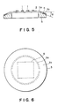
- Figure 1 is a sectional view showing an X-ray mask structure according to an embodiment of the present invention.
- Figure 2 is a top plan view of the mask structure.
- Supporting film 2 is stretched under tension and is bonded to a peripheral portion of a ring-like holding frame 3 by using an adhesive 4.
- the thickness of the thin film is preferably within a range of 1 - 20 microns.
- the ring-like holding frame 3 a material such as, for example, silicon, glass, quartz, phosphor bronze, brass, nickel or stainless steel is usable.
- No adhesive is applied to a topmost flat end face 3a of the frame 3. This is to avoid deterioration of the film flatness due to the intervention of any adhesive between the film and the flat end face.
- the dimension of the ring-like holding frame 3 usually it has an outer diameter of 50 - 120 mm and an inner diameter of 15 - 80 mm.
- the topmost flat end face 3a has a width which is usually about 2 mm.
- the topmost flat end face 3a is finished by means of a super-precision lathe process or a lapping process to a surface roughness not greater than 0.5 ⁇ m.Ra.
- the flatness can be examined by using an interferometer of dual-beam type using two lights.
- Figure 3 illustrates the interrelation between a radius r (mm) of an arbitrary region of the supporting film 2 and the flatness ⁇ (micron) in the region of the radius r.
- finishing precision of the topmost flat end face 3a is not required to be one providing a flatness exactly the same as the flatness required within the X-ray absorptive material pattern area 5.
- the flatness t of the topmost flat end face 3a may well be not greater than 2 microns. In other words, it is not necessary to finish the topmost flat end face 3a to a flatness not greater than 1 micron
- equation (3) can be rewritten as follows: ⁇ ⁇ t ⁇ 40/r x ⁇ (4)
- Figure 4 shows different examples wherein experiments were made by using different X-ray mask structures having ring-like holding frames of different inner diameters, to detect the interrelation between an arbitrary region having an arbitrary radius r and the flatness ⁇ within that region. It is seen from the results of those experiments that, where an inner diameter of a ring-like holding frame 3 is denoted by l, equation (4) can be rewritten as: ⁇ ⁇ t ⁇ l/r x ⁇ (5)
- the flatness t required for the topmost flat end face of the ring-like holding frame can be determined in accordance with equation (5).
- the topmost flat end face 3a is finished to a flatness t that satisfies equation (5). Since higher finishing precision necessitates a longer time and a higher cost, the simpleness of the present invention provides significant advantages such as substantial reduction in time necessary for the finishing and a resultant improvement in the throughput, as well as a substantial reduction in cost.
- the supporting film 2 As regards the tension to be applied to the supporting film 2, if it is smaller than 107 dyne/cm2, the supporting film 2 will be flexed due to the effect of its weight and, therefore, the flatness ⁇ of the supporting film 2 will not be maintained at a predetermined. If, on the other hand, the tension is greater than 109 dyne/cm2, the supporting film 2 will cause plastic deformation and the strength of the film will decrease, resulting in a possibility of breaking. With a tension which is within a range of 107 dyne/cm2 to 109 dyne/cm2, equation (5) applies sufficiently.
- the surface roughness of the topmost flat end face 3a is preferably not greater than 0.5 ⁇ m.Ra. If it is greater than 0.5 ⁇ m.Ra, due to such surface roughness there easily occurs wrinkles in a portion of the supporting film 2 adjacent to the topmost flat end face 3a, affecting against the flatness ⁇ .
- equation (5) representing that the flatness ⁇ depends only on t, r and l does not apply.
- the width of a topmost flat end face 3a may be made minimum within a range in which a predetermined flatness can be retained.
- the width may be made not greater than 0.5 mm.
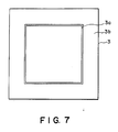
- the shape of the holding frame 3 is not limited to a ring.
- a rectangular shape such as shown in Figure 7 or a polygonal shape such as an octagonal shape, for example, are usable.
- l (mm) a radius of an inscribed circle inscribing the X-ray absorptive material pattern area
- ⁇ (micron) the flatness required for the X-ray absorptive material pattern area
- the flatness t (micron) of the topmost flat end face of the holding frame can be given by: ⁇ ⁇ t ⁇ r/l x ⁇
- the material of the holding frame is not limited to the disclosed examples such as quartz, glass and brass, and any other materials may be used provided that a desired flatness is obtainable by the finishing treatment.
- a flatness ⁇ required for an X-ray absorptive material pattern area 5 of a size 30 mm x 30 mm is not greater than 1 micron.
- the radius r of the X-ray absorptive pattern area 5 in that case is about 22 mm, since it is a half of the diagonal of the X-ray absorptive pattern area.
- the ring-like holding frame 3 was made by using a stainless steel SUS304 of a thickness 5 mm and had an outer diameter of 85 mm and an inner diameter of 65 mm.
- the topmost flat end face 3a had a width of 2 mm.
- equation (5) the following relation is derived: 0.1 (micron) ⁇ t ⁇ 32.5 (mm)/22 (mm) x 1 (micron)
- the flatness finishing precision for the topmost flat end face 3a should be not less than 0.1 micron and not greater than 1.47 micron.
- Ra 0.1 micron
- a flatness t 1.3 micron.
- a supporting film 2 ("Kapton film” having a thickness 7.5 microns, available from Toray Inc. Japan) was adhered at a bonding surface 3b, while a tension of 5x10⁷ dyne/cm2 was applied omnidirectionally to the supporting film.
- a ring-like holding frame 3 of a similar shape as that in Example 1 was used, and the width of a topmost flat end face 3a thereof was 0.5 mm.
- an X-ray absorptive material pattern 1 was formed on the thus obtained blank structure and, thereafter, the flatness ⁇ in the X-ray absorptive pattern area 5 was measured by using a dual-beam interferometer. The result is that in a region of 30 mm x 30 mm a flatness of 0.82 micron was assured. Further, it was confirmed that, due to the reduced width (0.5 mm) of the topmost flat end face 3a, substantially no foreign particle entered into between the supporting film 2 and the topmost end face 3a and, as a result, a better flatness can be obtained throughout the X-ray absorptive material pattern area.
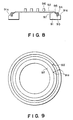
- Figures 8 and 9 show an X-ray mask structure according to a further embodiment of the present invention, wherein Figure 8 is a sectional view and Figure 9 is a top plan view.
- a ring-like holding frame which is made of metal having a good heat conductivity such as, for example, iron, nickel, cobalt, brass, tungsten or molybdenum, or an alloy of two or more of them or, alternatively, it is made of pyrex, quartz or otherwise having a low thermal expansion rate.
- an inclined portion 91a which is inclined radially outwardly is formed.
- a flat surface portion 97 having been ground to a super flatness is formed.
- this flat surface portion 97 is effective to determine the flatness of a supporting film 92 which is to be adhered thereto under tension, as will be described later.
- Denoted at 92 is the supporting film which is provided by an organic thin film having a good X-ray transmission factor and being made of a material such as polyimide, polyamide, polyester or Parylene, or an inorganic thin film made of a material such as boron nitride, silicon nitride, aluminum nitride, silicon carbide or titanium, or, alternatively, it is provided by a film made of a composite of two or more of them.
- Denoted at 96 is an X-ray absorptive material formed into a predetermined pattern lying on the supporting film 92 surface.
- Denoted at 93 is a groove extending in the form of a circle concentric with the holding frame 91 which is circular in this embodiment.
- the groove 93 is formed at a position inwardly by about 3 mm, for example, of the outer periphery of the inclined portion 91a of the ring of the holding frame 91, and it has a channel-like cross-sectional shape, having a width of about 2 mm and a depth of about 1 mm.
- the supporting film 92 is adhered to the holding frame 91 in the following manner: First, the supporting film 92 to which a tension of about 7x10⁸ dyne/cm2 being applied is contacted to and pressed against the flat surface portion 97 and the inclined portion 91a surface of the holding frame 91, the contacted supporting film being bonded to the holding frame with the setting of an adhesive 95 which is applied to the inclined portion 91a.
- a bonding agent (“Bond G10", available from Konishi Kabushiki Kaisha, Japan) was applied to a ring-like or circumferential portion of the inclined surface 91a of the holding frame 91, inside the groove 93 and having a width of about 5 mm.
- the peripheral edge portion of the supporting film 92 is cut along the outer circumferential edge of the holding frame 91 and, further, it is cut and shaped so that the peripheral edge portion of the supporting film 92 can be embedded within the groove 93.
- an adhesive material 94 such as an epoxy resin, for example, is injected into the groove 93 so that approximately a half depth of the groove is filled with the adhesive material.
- the outer circumferential portion of the supporting film 92 is inserted into the groove 93.
- an additional amount of adhesive material 94 is applied to the groove 93 so that it provides a height substantially equal to the height of the inclined surface.
- Examples of the material of an adhesive usable in this embodiment are elastomeric adhesive, epoxy adhesive, emulsion adhesive, amine adhesive and polyimide adhesive. Thermosetting type, photo-setting type, solvent type or otherwise is usable. Particularly, use of an adhesive having high shear strength and good heat resistivity is preferable.
- the groove 93 provided in the inclined portion 91a of the holding frame 91 of the present embodiment is not limited to one having a channel-like sectional shape.
- a V-shaped groove, a U-shaped groove or a slit-like groove may be used.
- the groove 93 may be formed with inclination, being inclined radially outwardly. This is desirable because it facilitates insertion of the outer peripheral portion of the supporting film 92.
Landscapes
- Physics & Mathematics (AREA)
- General Physics & Mathematics (AREA)
- Preparing Plates And Mask In Photomechanical Process (AREA)
- Exposure Of Semiconductors, Excluding Electron Or Ion Beam Exposure (AREA)
Applications Claiming Priority (4)
| Application Number | Priority Date | Filing Date | Title |
|---|---|---|---|
| JP95323/88 | 1988-04-18 | ||
| JP63095323A JPH01266723A (ja) | 1988-04-18 | 1988-04-18 | リソグラフィ用マスクの構造体 |
| JP243915/88 | 1988-09-30 | ||
| JP63243915A JPH0294425A (ja) | 1988-09-30 | 1988-09-30 | X線マスク構造体 |
Publications (2)
| Publication Number | Publication Date |
|---|---|
| EP0338749A2 true EP0338749A2 (fr) | 1989-10-25 |
| EP0338749A3 EP0338749A3 (fr) | 1990-05-02 |
Family
ID=26436570
Family Applications (1)
| Application Number | Title | Priority Date | Filing Date |
|---|---|---|---|
| EP89303779A Withdrawn EP0338749A3 (fr) | 1988-04-18 | 1989-04-17 | Structure pour masque pour rayons X |
Country Status (1)
| Country | Link |
|---|---|
| EP (1) | EP0338749A3 (fr) |
Cited By (2)
| Publication number | Priority date | Publication date | Assignee | Title |
|---|---|---|---|---|
| EP0452043A1 (fr) * | 1990-04-09 | 1991-10-16 | Canon Kabushiki Kaisha | Structure de masque pour exposition aux rayons X |
| EP2587312A1 (fr) * | 2011-10-24 | 2013-05-01 | Shin-Etsu Chemical Co., Ltd. | Substrat de verre de qualité électronique et son procédé de fabrication |
Family Cites Families (2)
| Publication number | Priority date | Publication date | Assignee | Title |
|---|---|---|---|---|
| DE3435177A1 (de) * | 1983-09-26 | 1985-04-11 | Canon K.K., Tokio/Tokyo | Maske fuer lithographische zwecke |
| DE3524196C3 (de) * | 1984-07-06 | 1994-08-04 | Canon Kk | Lithografiemaske |
-
1989
- 1989-04-17 EP EP89303779A patent/EP0338749A3/fr not_active Withdrawn
Cited By (5)
| Publication number | Priority date | Publication date | Assignee | Title |
|---|---|---|---|---|
| EP0452043A1 (fr) * | 1990-04-09 | 1991-10-16 | Canon Kabushiki Kaisha | Structure de masque pour exposition aux rayons X |
| US5356686A (en) * | 1990-04-09 | 1994-10-18 | Canon Kabushiki Kaisha | X-ray mask structure |
| EP2587312A1 (fr) * | 2011-10-24 | 2013-05-01 | Shin-Etsu Chemical Co., Ltd. | Substrat de verre de qualité électronique et son procédé de fabrication |
| US9205528B2 (en) | 2011-10-24 | 2015-12-08 | Shin-Etsu Chemical Co., Ltd. | Electronic grade glass substrate and making method |
| US9902037B2 (en) | 2011-10-24 | 2018-02-27 | Shin-Etsu Chemical Co., Ltd. | Electronic grade glass substrate and making method |
Also Published As
| Publication number | Publication date |
|---|---|
| EP0338749A3 (fr) | 1990-05-02 |
Similar Documents
| Publication | Publication Date | Title |
|---|---|---|
| US5032544A (en) | Process for producing semiconductor device substrate using polishing guard | |
| KR101780063B1 (ko) | 펠리클 프레임 및 리소그래피용 펠리클 | |
| EP0850724B1 (fr) | Dispositif de meulage de surface et procédé de meulage en surface d'une pièce mince et plane | |
| US6030280A (en) | Apparatus for holding workpieces during lapping, honing, and polishing | |
| KR960015777A (ko) | 폴리싱장치 | |
| JP3244894B2 (ja) | マスク保持方法、マスク及びマスクチャック、ならびにこれを用いた露光装置とデバイス製造方法 | |
| JPH0758066A (ja) | ウェーハの研磨方法 | |
| EP0685299A1 (fr) | Tampon pour le polissage de plaquettes semi-conductrices et procédé de mise en oeuvre | |
| EP0338749A2 (fr) | Structure pour masque pour rayons X | |
| JPH0590137A (ja) | 露出マスク | |
| JP3709016B2 (ja) | 光学薄膜の製造方法 | |
| US6303196B1 (en) | Pellicle | |
| EP0499084A1 (fr) | Plateau de montage pour wafer | |
| JP6461659B2 (ja) | ペリクル枠体及びペリクル | |
| JP3232232B2 (ja) | X線取り出し窓およびその製造方法ならびに前記x線取り出し窓を用いたx線露光装置 | |
| KR100223023B1 (ko) | X-선 마스크 | |
| JPH1070066A (ja) | X線マスク構造体、該x線マスク構造体を用いたx線露光方法、前記x線マスク構造体を用いたx線露光装置、前記x線マスク構造体を用いた半導体デバイスの製造方法及び該製造方法によって製造された半導体デバイス | |
| JP5731147B2 (ja) | ペリクル用枠体及びペリクル | |
| JP2912692B2 (ja) | X線マスクの製造方法 | |
| JP2001170853A (ja) | 研削・研磨加工用の光学素子保持具 | |
| JP3405732B2 (ja) | フレームへの光学ペリクル膜の接着方法 | |
| JP5579545B2 (ja) | 大型ペリクル用枠体、大型ペリクル及び大型ペリクル用枠体の製造方法 | |
| KR0179907B1 (ko) | X선 마스크 및 그 제조방법 | |
| US5590239A (en) | Planar uniform heating surface with additional circumscribing ring | |
| JPH0294425A (ja) | X線マスク構造体 |
Legal Events
| Date | Code | Title | Description |
|---|---|---|---|
| PUAI | Public reference made under article 153(3) epc to a published international application that has entered the european phase |
Free format text: ORIGINAL CODE: 0009012 |
|
| AK | Designated contracting states |
Kind code of ref document: A2 Designated state(s): DE FR GB NL |
|
| PUAL | Search report despatched |
Free format text: ORIGINAL CODE: 0009013 |
|
| AK | Designated contracting states |
Kind code of ref document: A3 Designated state(s): DE FR GB NL |
|
| 17P | Request for examination filed |
Effective date: 19900918 |
|
| 17Q | First examination report despatched |
Effective date: 19930331 |
|
| STAA | Information on the status of an ep patent application or granted ep patent |
Free format text: STATUS: THE APPLICATION IS DEEMED TO BE WITHDRAWN |
|
| 18D | Application deemed to be withdrawn |
Effective date: 19930811 |