EP0338443B1 - Verbinder zum Verbinden zweier Bauelemente - Google Patents
Verbinder zum Verbinden zweier Bauelemente Download PDFInfo
- Publication number
- EP0338443B1 EP0338443B1 EP89106684A EP89106684A EP0338443B1 EP 0338443 B1 EP0338443 B1 EP 0338443B1 EP 89106684 A EP89106684 A EP 89106684A EP 89106684 A EP89106684 A EP 89106684A EP 0338443 B1 EP0338443 B1 EP 0338443B1
- Authority
- EP
- European Patent Office
- Prior art keywords
- fitting
- screw
- fitting according
- adjusting device
- lever
- Prior art date
- Legal status (The legal status is an assumption and is not a legal conclusion. Google has not performed a legal analysis and makes no representation as to the accuracy of the status listed.)
- Expired - Lifetime
Links
- 238000010276 construction Methods 0.000 claims 1
- 239000000853 adhesive Substances 0.000 description 2
- 230000001070 adhesive effect Effects 0.000 description 2
- 229920001296 polysiloxane Polymers 0.000 description 2
- 230000008878 coupling Effects 0.000 description 1
- 238000010168 coupling process Methods 0.000 description 1
- 238000005859 coupling reaction Methods 0.000 description 1
- 238000006073 displacement reaction Methods 0.000 description 1
- 210000001503 joint Anatomy 0.000 description 1
- 238000000034 method Methods 0.000 description 1
Images



Classifications
-
- F—MECHANICAL ENGINEERING; LIGHTING; HEATING; WEAPONS; BLASTING
- F16—ENGINEERING ELEMENTS AND UNITS; GENERAL MEASURES FOR PRODUCING AND MAINTAINING EFFECTIVE FUNCTIONING OF MACHINES OR INSTALLATIONS; THERMAL INSULATION IN GENERAL
- F16B—DEVICES FOR FASTENING OR SECURING CONSTRUCTIONAL ELEMENTS OR MACHINE PARTS TOGETHER, e.g. NAILS, BOLTS, CIRCLIPS, CLAMPS, CLIPS OR WEDGES; JOINTS OR JOINTING
- F16B12/00—Jointing of furniture or the like, e.g. hidden from exterior
- F16B12/10—Jointing of furniture or the like, e.g. hidden from exterior using pegs, bolts, tenons, clamps, clips, or the like
- F16B12/12—Jointing of furniture or the like, e.g. hidden from exterior using pegs, bolts, tenons, clamps, clips, or the like for non-metal furniture parts, e.g. made of wood, of plastics
- F16B12/20—Jointing of furniture or the like, e.g. hidden from exterior using pegs, bolts, tenons, clamps, clips, or the like for non-metal furniture parts, e.g. made of wood, of plastics using clamps, clips, wedges, sliding bolts, or the like
- F16B12/2009—Jointing of furniture or the like, e.g. hidden from exterior using pegs, bolts, tenons, clamps, clips, or the like for non-metal furniture parts, e.g. made of wood, of plastics using clamps, clips, wedges, sliding bolts, or the like actuated by rotary motion
- F16B12/2054—Jointing of furniture or the like, e.g. hidden from exterior using pegs, bolts, tenons, clamps, clips, or the like for non-metal furniture parts, e.g. made of wood, of plastics using clamps, clips, wedges, sliding bolts, or the like actuated by rotary motion with engaging screw threads as securing means for limiting movement
- F16B12/2063—Jointing of furniture or the like, e.g. hidden from exterior using pegs, bolts, tenons, clamps, clips, or the like for non-metal furniture parts, e.g. made of wood, of plastics using clamps, clips, wedges, sliding bolts, or the like actuated by rotary motion with engaging screw threads as securing means for limiting movement with engaging screw threads as tightening means
-
- A—HUMAN NECESSITIES
- A47—FURNITURE; DOMESTIC ARTICLES OR APPLIANCES; COFFEE MILLS; SPICE MILLS; SUCTION CLEANERS IN GENERAL
- A47B—TABLES; DESKS; OFFICE FURNITURE; CABINETS; DRAWERS; GENERAL DETAILS OF FURNITURE
- A47B95/00—Fittings for furniture
-
- E—FIXED CONSTRUCTIONS
- E04—BUILDING
- E04B—GENERAL BUILDING CONSTRUCTIONS; WALLS, e.g. PARTITIONS; ROOFS; FLOORS; CEILINGS; INSULATION OR OTHER PROTECTION OF BUILDINGS
- E04B1/00—Constructions in general; Structures which are not restricted either to walls, e.g. partitions, or floors or ceilings or roofs
- E04B1/38—Connections for building structures in general
- E04B1/61—Connections for building structures in general of slab-shaped building elements with each other
- E04B1/6108—Connections for building structures in general of slab-shaped building elements with each other the frontal surfaces of the slabs connected together
- E04B1/6187—Connections for building structures in general of slab-shaped building elements with each other the frontal surfaces of the slabs connected together by means on top and/or bottom surfaces of the slabs
-
- F—MECHANICAL ENGINEERING; LIGHTING; HEATING; WEAPONS; BLASTING
- F16—ENGINEERING ELEMENTS AND UNITS; GENERAL MEASURES FOR PRODUCING AND MAINTAINING EFFECTIVE FUNCTIONING OF MACHINES OR INSTALLATIONS; THERMAL INSULATION IN GENERAL
- F16B—DEVICES FOR FASTENING OR SECURING CONSTRUCTIONAL ELEMENTS OR MACHINE PARTS TOGETHER, e.g. NAILS, BOLTS, CIRCLIPS, CLAMPS, CLIPS OR WEDGES; JOINTS OR JOINTING
- F16B12/00—Jointing of furniture or the like, e.g. hidden from exterior
- F16B12/10—Jointing of furniture or the like, e.g. hidden from exterior using pegs, bolts, tenons, clamps, clips, or the like
Definitions
- the invention relates to a fitting with two fitting parts for connecting two components, preferably for connecting two plates at the end, a fitting part being inserted in each component in the connection area and at least one clamping screw or the like being provided, each of which is mounted in one of the fitting parts and is supported on the other and which exerts a tensile force connecting the fitting parts in one clamping direction, with an adjusting device for adjusting the mutual position of the fitting parts and thus the components essentially perpendicular to the clamping direction.
- a fitting is known from US-A-3236487, in which the two fitting parts are connected by means of a horizontal clamping screw.
- a height adjustment screw which presses on the other fitting part, is stored in one of the fitting parts. By turning the height adjustment screw, it is therefore possible to adjust the height of the plates in relation to one another.
- the conventional connectors have the disadvantage that a relatively large amount of space must be available laterally when assembling the plates, ie in the direction of tension of the tensioning screws, since the plates must first be brought at least approximately into a common horizontal plane and only then the end face of one plate is laterally brought up to the end face of the other plate.
- the object of the invention is to provide a fitting with which the one plate lying directly next to the other plate can be brought up to this from above, so that laterally no more space is required during assembly than is necessary for the assembled plates.
- Another object of the invention is to improve a fitting of the type mentioned at the outset in such a way that the two fitting parts can be coupled, at least provisionally, quickly and without using a tool.
- an elastic or elastically loaded locking part is arranged in a fitting part, which engages or snaps in the case of assembled fitting parts in the adjusting device mounted in the other fitting part.
- the resilient locking part can initially deflect against a spring force and then snap or snap onto the (height) adjustment device in the other fitting part, whereupon there is already the possibility of mutual adjustment of the plates.
- the locking part arranged in a fitting part with fitting parts in the connecting position in is elastically loaded or pretensioned essentially in the direction of the other fitting part, a simple "locking" of the adjusting device with the locking part is achieved in a certain range, independent of the relative position of the two fitting parts in the clamping direction.
- a safe height adjustment is always guaranteed. It is even possible to lightly clamp the plates together, then make the correct relative height adjustment by feeling with the finer, then slide the plates apart again to put adhesive or silicone between the plates, and finally finally clamp the plates together. With such movements in the tensioning direction, the elastically loaded locking part follows the (height) adjustment device of the other fitting part and thus ensures that the height adjustment is maintained.
- the adjusting device is a screw with a disk-shaped head on which the locking part engages.
- An embodiment of the invention provides that the locking part is a spring leaf yielding in the pulling direction, which has a slot in which the head of the screw engages with its edge.
- the spring leaf can be held in the fitting part by two webs which have slots in which the spring leaf is supported.
- one of the fitting parts is pot-shaped and the other fitting part an extension is formed which can be inserted in the first fitting part substantially perpendicular to the clamping direction.
- the locking part is a lever which is rotatably mounted on a vertical axis and acted upon by a spring.
- the lever is advantageously guided positively in the fitting part, i.e. it cannot move up or down. If the lever now has a notch with an upper and a lower stop surface, in which the head of the screw engages with its edge, the fitting part in which the screw is mounted can be turned by turning the screw with respect to the fitting part in which the Lever is mounted, the height can be adjusted.
- the lever has an inclined surface at its lower edge in the area of the screw, because then the lever automatically withdraws first and then automatically by the adjusting device clicks into place.
- the notch is segment-like in plan view.
- an eccentric is provided in a further preferred exemplary embodiment of the invention, with which the lever can be pivoted against the spring pressure and thus from the head of the screw, which on the one hand forms the height adjustment part and on the other hand the snap-in part, can be lifted off.
- clamping screw and the screw of the adjusting device are aligned parallel to one another and that the clamping screw has a conical tip with which it presses against a wedge surface of the other housing part.
- the clamping screw and the screw of the adjusting device are arranged next to one another transversely to the clamping direction of the fitting parts.
- fitting parts are cup-shaped and have at least one flange with one or more fastening screws.
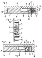
- FIG. 1 shows a plan view of a fitting according to the invention
- FIG. 2 shows a view from below of the fitting according to the invention
- FIG. 3 shows a section along the line CD of FIG. 2
- FIG. 4 shows a section along the line GH of FIG. 2
- FIG. 5 shows a section along the line EF of FIG. 2
- FIG. 6 shows the View J of FIG. 3
- FIG. 7 shows a plan view of a further exemplary embodiment of a fitting
- FIG. 8 shows a section along the line IK of FIG. 7
- FIG. 9 shows the spring leaf
- FIG. 10 shows it schematically the assembly of two components with a fitting according to the invention.
- FIGS. 1 to 6 The exemplary embodiment according to FIGS. 1 to 6 is described below.
- the fitting shown in the figures for the firm and exact connection of the two worktops 10, 11 consists of the two fitting parts 1, 2, which can each be inserted into a recess milled into the worktops 10, 11.
- the fitting parts 1, 2 are designed in the form of a housing with a pot 12 and a flange 13. Holes 14 for the fastening screws 15 are located in the flanges 13.
- the fitting part 1 has an extension 16 protruding into the fitting part 2, in which the tensioning screw 7 and the screw 6, which forms the adjusting device, are mounted.
- the clamping screw 7 and the screw 6 are aligned vertically in the assembly position, i.e. perpendicular to the clamping direction S, which is generally horizontal, in order to pull the two plates 10, 11 together with their end faces.
- the clamping screw 7 is therefore provided with a conical tip 17 which, as can be seen from FIG. 5, bears against a wedge surface 18 of a projection 19 of the fitting part 2. The further the clamping screw 7 in the fitting part 1 is screwed in, the more the fittings 1 and 2 are clamped together.
- a lever 3 is mounted in the fitting part 2 on a bearing pin 8, which forms a vertical axis.
- the lever 3 is acted upon by a helical spring 4.
- the lever 3 Opposite the coil spring 4, the lever 3 is provided with a notch 20 which is delimited by an upper and lower stop surface 21, 22.
- the notch 20 is segment-shaped in plan view, as can be seen in particular from FIG. 2.
- the lever 3 is provided with an inclined surface 23 at least in the area of the screw 6.
- Fig. 10 shows the position of how the two plates 10, 11 are assembled. If the plate 11, as indicated by the arrow in FIG. 10, is pressed down, the screw 6 initially presses the lever 3 against the pressure of the spring 4 with its head and the fitting part 2 can be pushed down as far with the lever 3 are moved until the head 9 of the screw engages in the notch 20. Since the clamping screw 7 bears behind the projection 19 at the same time, the fitting parts 1, 2 are thus automatically coupled to one another. The lever 3 acts as a latch part. Starting from this provisional coupling position (holding position), the height adjustment described below and then the plates can be clamped together.
- the head 9 of the screw 6 is held in a positive manner in the lever 3.
- the fitting part 1 can now be moved up or down with respect to the fitting part 1.
- the lever 3 as shown in FIG. 5 is also advantageously held between two plates 24, 25, the former binding the bottom of the housing 12.
- an eccentric 5 is mounted in the fitting part 2.
- the lever 3, as shown in FIG. 6, can be lifted laterally against the pressure of the helical spring 4 from the head 9 of the screw 6, whereby the connection between the two fitting parts 1, 2 is released.
- the flanges 13 of the fitting parts 1, 2 are each received in a recess 26 in the plates 10, 11.
- a spring leaf 27 is arranged in the fitting part 2 instead of the lever 3.
- the spring leaf 27 is supported by webs 28 of the fitting part 2, which have slots 29 in which the spring leaf 27 is supported.
- the spring leaf 27 is bent towards the screw 6 and can deflect in the direction of arrow A.
- the screw 6 which is the adjustment device for the height adjustment of the fitting and the clamping screw one behind the other, ie in the clamping direction.
- the clamping screw 7 in turn presses with its tip 17 onto the wedge surface 18 of the projection 19 of the fitting part 2.
- the clamping screw 7 and the screw 6 are in turn mounted in an extension 16 of the fitting part 1.
- the spring leaf 27 is provided with a slot 30. Below the slot 30, an inclined surface 31 is formed, which corresponds to the inclined surface 23 of the lever 3.
- the head 9 of the screw 3 travels along the inclined surface 31 of the spring plate 27 and presses it back in the direction of the arrow A in FIG. 7 until it engages in the slot 30. Since the screw 7 in turn rests with its tip 17 on the projection 19, the two fitting parts 1, 2 are automatically locked. Instead of the slot 30, under certain circumstances only a depression, i.e. again a notch analogous to the previously described embodiment may be provided. It is only important that the head 9 cannot slip out of the spring leaf 27 unintentionally.
- the head 9 between the edges 32, 33 of the slot 30 is kept so tight that by turning the screw 6 again the height adjustment of the fitting parts 1, 2 with respect to one another is possible.
- the two components or the two fitting parts 1, 2 can be shifted slightly in or against the tensioning direction S, the resilient locking part 3 or 27 simply going along and remaining connected to the height adjustment device.
- Such a shift in the clamping direction occurs when the worktops are braced, the extent of the shift also being able to depend on the reworking of the end faces of the boards, for example carried out by the installer.
- maintaining the height adjustment with relative displacements of the fitting parts 1, 2 or plates in or against the clamping direction is particularly advantageous: after preassembly from the position shown in FIG. 10, in which the locking part 3 in the The height adjustment device snaps in or snaps on (plate 9 enters groove 20, FIG. 3) is slightly clamped together using the clamping screw 7.
- the fittings 1,2 are advantageously made of plastic or die-cast.
Landscapes
- Engineering & Computer Science (AREA)
- General Engineering & Computer Science (AREA)
- Architecture (AREA)
- Mechanical Engineering (AREA)
- Civil Engineering (AREA)
- Electromagnetism (AREA)
- Physics & Mathematics (AREA)
- Structural Engineering (AREA)
- Connection Of Plates (AREA)
- Details Of Connecting Devices For Male And Female Coupling (AREA)
- Snaps, Bayonet Connections, Set Pins, And Snap Rings (AREA)
- Electrophotography Configuration And Component (AREA)
- Exchange Systems With Centralized Control (AREA)
- Control Of Motors That Do Not Use Commutators (AREA)
Description
- Die Erfindung bezieht sich auf einen Beschlag mit zwei Beschlagteilen zum Verbinden zweier Bauelemente, vorzugsweise zum stirnseitigen Verbinden zweier Platten, wobei in jedes Bauelement im Verbindungsbereich ein Beschlagteil eingesetzt und mindestens eine Spannschraube od. dgl. vorgesehen ist, die jeweils in einem der Beschlagteile lagert und am anderen abgestützt ist und die in einer Spannrichtung eine die Beschlagteile verbindende Zugkraft ausübt, mit einer Verstelleinrichtung zur Einstellung der gegenseitigen Lage der Beschlagteile und somit der Bauelemente im wesentlichen senkrecht zur Spannrichtung.
- Derartige Beschläge sind bereits in den verschiedensten Ausführungen bekannt. Insbesondere beim stirnseitigen Verbinden von Platten ist es wichtig, daß die Oberflächen genau in einer Ebene liegen, da auch eine geringe Stufe die Arbeit auf der Platte sehr behindern würde. Außerdem sind solche Stufen aus ästhetischen Gründen unvorteilhaft. Bei vielen Verbindern, die nur einen Zuganker aufweisen, konnten die Platten oder die Bauelemente nur durch mühsames und zeitaufwendiges Zurechtrücken in die richtige Lage gebracht werden.
- Aus der US-A-3236487 ist ein Beschlag bekannt, bei dem die beiden Beschlagteile mittels einer horizontalen Spannschraube verbunden werden. In einem der Beschlagteile lagert eine Höhenverstellschraube, die auf den anderen Beschlagteil drückt. Durch Verdrehen der Höhenverstellschraube ist es daher möglich, die Höhenadjustierung der Platten in bezug aufeinander durchzuführen. Die herkömmlichen Verbinder haben den Nachteil, daß beim Zusammenbau der Platten seitlich, d.h. in der Zugrichtung der Spannschrauben relativ viel Platz vorhanden sein muß, da die Platten zuerst zumindestens ungefähr in eine gemeinsame horizontale Ebene gebracht werden müssen und dann erst die Stirnseite einer Platte an die Stirnseite der anderen Platte seitlich herangeführt wird.
- Aufgabe der Erfindung ist es, einen Beschlag zu schaffen, mit dem die eine Platte unmittelbar neben der anderen Platte liegend an diese von oben herangeführt werden kann, sodaß während der Montage seitlich nicht mehr Platz beansprucht wird, als für die zusammengefügten Platten notwendig ist.
- Eine weitere Aufgabe der Erfindung ist es, einen Beschlag der eingangs erwähnten Art dahin zu verbessern, daß die beiden Beschlagteile rasch und ohne Verwendung eines Werkzeugs zumindest provisorisch kuppelbar sind.
- Die erfindungsgemäßen Aufgaben werden dadurch gelöst, daß in einem Beschlagteil ein elastischer oder elastisch beaufschlagter Riegelteil angeordnet ist, der bei zusammengesetzten Beschlagteilen bei der im anderen Beschlagteil gelagerten Verstelleinrichtung einrastet bzw. aufrastet.
- Damit ist es auch möglich, die eine Platte von oben heranzuführen und so in die Verbindungsstellung zu bringen. (Fig. 10) Der federnde Riegelteil kann zunächst entgegen einer Federkraft ausweichen und darauf bei der (Höhen)Verstelleinrichtung im anderen Beschlagteil einrasten bzw. aufrasten, worauf bereits die Möglichkeit einer gegenseitigen Einstellung der Platten gegeben ist.
- Durch eine bevorzugte Ausbildung, bei der vorgesehen ist, daß der in einem Beschlagteil angeordnete Riegelteil bei in Verbindungsstellung befindlichen Beschlagteilen im wesentlichen in Richtung zum anderen Beschlagteil hin elastisch beaufschlagt bzw. vorgespannt ist, erreicht man auf einfache Weise eine in einem bestimmten Bereich von der Relativlage der beiden Beschlagteile in Spannrichtung unabhängige sichere "Verrastung" der Verstelleinrichtung mit dem Riegelteil. Bei Toleranzen in den Nachbearbeitungen der Stirnflächen und beim Zusammenspannen der Platten bleibt damit immer eine sichere Höhenverstellung gewährleistet. Es ist sogar möglich, die Platten leicht zusammenzuspannen, dann etwa durch Abfühlen mit dem Finer die richtige relative Höheneinstellung vorzunehmen, hierauf die Platten wieder etwas auseinanderzuschieben, um Klebstoff oder Silikon zwischen die Platten zu geben, und schließlich die Platten endgültig zusammenzuspannen. Bei solchen Bewegungen in Spannrichtung folgt der elastisch beaufschlagte Riegelteil der (Höhen)Verstelleinrichtung des anderen Beschlagteiles und stellt somit ein Aufrechterhalten der Höhenjustage sicher.
- Vorteilhaft ist vorgesehen, daß die Verstelleinrichtung eine Schraube mit einem scheibenförmigen Kopf ist, an dem der Riegelteil angreift.
- Ein Ausführungsbeispiel der Erfindung sieht vor, daß der Riegelteil ein in Zugrichtung nachgebendes Federblatt ist, das einen Schlitz aufweist, in dem der Kopf der Schraube mit seinem Rand einrastet.
- Das Federblatt kann von zwei Stegen im Beschlagteil gehalten sein, die Schlitze aufweisen, in denen das Federblatt lagert.
- Vorteilhaft ist vorgesehen, daß einer der Beschlagteile topfartig ausgeführt ist und am anderen Beschlagteil ein Fortsatz ausgebildet ist, der in den ersten Beschlagteil im wesentlichen senkrecht zur Spannrichtung einsetzbar ist.
- Ein weiteres Ausführungsbeispiel der Erfindung sieht vor, daß der Riegelteil ein auf einer senkrechten Achse drehbar gelagerter und von einer Feder beaufschlagter Hebel ist.
- Der Hebel ist im Beschlagteil vorteilhaft formschlüssig geführt, d.h. er kann weder nach oben noch nach unten ausweichen. Wenn nun der Hebel eine Einkerbung mit einer oberen und einer unteren Anschlagfläche aufweist, in welcher der Kopf der Schraube mit seinem Rand einrastet, so kann der Beschlagteil, in dem die Schraube lagert, durch Verdrehen der Schraube in bezug auf dem Beschlagteil, in dem der Hebel gelagert ist, in der Höhe verstellt werden.
- Um das Aufdrücken des einen Beschlagteiles auf den anderen und das Ausweichen des Hebels zu erleichtern, ist vorteilhaft vorgesehen, daß der Hebel an seinem unteren Rand im Bereich der Schraube eine Schrägfläche aufweist, weil dann der Hebel zunächst automatisch zurückweicht und dann von selbst bei der Verstelleinrichtung ein- bzw. aufrastet.
- Die Einkerbung ist in Draufsicht segmentartig.
- Damit die beiden Beschlagteile des Beschlages auf einfache Art voneinander lösbar sind, ist in einem weiteren bevorzugten Ausführungsbeispiel der Erfindung ein Exzenter vorgesehen, mit dem der Hebel gegen den Federdruck schwenkbar und somit vom Kopf der Schraube, die einerseits den Höhenverstellteil und andererseits den Einrastteil bildet, abhebbar ist.
- Vorteilhaft ist weiters vorgesehen, daß die Spannschraube und die Schraube der Verstelleinrichtung parallel zueinander ausgerichtet sind und die Spannschraube eine konische Spitze aufweist, mit der sie an eine Keilfläche des anderen Gehäuseteiles drückt.
- Durch Einrasten bzw. Aufrasten des elastisch beaufschlagten bzw. elastischen Riegelteiles in die Verstelleinrichtung und gleichzeitiges Anliegen der Spannschraube od.dgl. an einer Schrägfläche des anderen Beschlagteiles kann man eine rasche provisorische Vorberbindung, von der aus noch eine Höhenjustierung und ein Zusammenspannen nötig ist, einfach und ohne Werkzeug erreichen.
- Gemäß einer bevorzugten Ausführungsform ist vorgesehen, daß die Spannschraube und die Schraube der Verstelleinrichtung quer zur Spannrichtung der Beschlagteile nebeneinander angeordnet sind.
- Man geht dabei davon aus daß zum Verbinden zweier Platten mindestens zwei Beschläge notwendig sind. Daher spielt es keine Rolle, wenn die Spannschraube außermittig angeordnet ist. Die auftretenden Drehmomente werden im Gesamtsystem ausgeglichen.
- Weiters ist vorgesehen, daß die Beschlagteile topfförmig sind und mindestens einen Flansch mit einer oder mehreren Befestigungsschrauben aufweisen.
- Nachfolgend werden zwei Ausführungsbeispiele der Erfindung anhand der Figuren der beiliegenden Zeichnungen eingehend beschrieben.
- Die Fig. 1 zeigt eine Draufsicht auf einen erfindungsgemäßen Beschlag die Fig. 2 zeigt eine Ansicht von unten auf den erfindungsgemäßen Beschlag, die Fig. 3 zeigt einen Schnitt nach der Linie C-D der Fig. 2, die Fig. 4 zeigt einen Schnitt nach der Linie G-H der Fig. 2, die Fig. 5 zeigt einen Schnitt nach der Linie E-F der Fig. 2, die Fig. 6 zeigt die Ansicht J der Fig.3, die Fig. 7 zeigt eine Draufsicht auf ein weiteres Ausführungsbeispiel eines Beschlages die Fig. 8 zeigt einen Schnitt nach der Linie I-K der Fig. 7, die Fig. 9 zeigt schaubildlich das Federblatt und die Fig. 10 zeigt schematisch das Zusammensetzen zweier Bauelemente mit einem erfindungsgemäßen Beschlag.
- Nachfolgend wird das Ausführungsbeispiel nach den Fig. 1 bis 6 beschrieben.
- Der in den Figuren dargestellte Beschlag zur festen und exakten Verbindung der beiden Arbeitsplatten 10, 11 besteht aus den beiden Beschlagteilen 1,2, die jeweils in eine in die Arbeitsplatten 10,11 eingefräste Aussparung einsetzbar sind. Dabei sind die Beschlagteile 1,2 gehäuseförmig mit einem Topf 12 und einem Flansch 13 ausgeführt. In den Flanschen 13 befinden sich Löcher 14 für die Befestigungsschrauben 15. Der Beschlagteil 1 weist einen in den Beschlagteil 2 ragenden Fortsatz 16 auf, in dem die Spannschraube 7 sowie die Schraube 6, die die Verstelleinrichtung bildet, lagern.
- Die Spannschraube 7 sowie die Schraube 6 sind dabei in Montagelage vertikal ausgerichtet, d.h. senkrecht zur Spannrichtung S, die im allgemeinen horizontal verläuft, um die beiden Platten 10,11 mit ihren Stirnseiten aneinander zu ziehen.
- Die Spannschraube 7 ist daher mit einer konischen Spitze 17 versehen, die wie aus der Fig. 5 ersichtlich, an einer Keilfläche 18 eines Vorsprunges 19 des Beschlagteiles 2 anliegt. Je weiter die Spannschraube 7 in den Beschlagteil 1 hineingeschraubt wird, desto mehr werden die Beschlagteile 1 und 2 miteinander verspannt.
- Die Schraube 6, die die Verstelleinrichtung bildet, dient außerdem noch der Verriegelung bzw. Kupplung der beiden Beschlagteile 1,2. Sie weist einen scheibenförmigen Kopf 9 auf.
- Im Beschlagteil 2 lagert auf einem Lagerbolzen 8, der eine senkrechte Achse bildet, ein Hebel 3. Der Hebel 3 wird von einer Schraubenfeder 4 beaufschlagt.
- Der Schraubenfeder 4 gegenüberliegend ist der Hebel 3 mit einer Einkerbung 20 versehen, die von einer oberen und unteren Anschlagfläche 21, 22 begrenzt wird. Die Einkerbung 20 ist in Draufsicht, wie insbesondere aus der Fig. 2 ersichtlich, segmentförmig.
- Unten ist der Hebel 3 zumindestens im Bereich der Schraube 6 mit einer Schrägfläche 23 versehen.
- Die Fig. 10 zeigt die Stellung, wie die beiden Platten 10, 11 zusammengefügt werden. Wird die Platte 11, wie der Pfeil in der Fig. 10 anzeigt, nach unten gedrückt, so drückt die Schraube 6 mit ihrem Kopf vorerst den Hebel 3 entgegen den Druck der Feder 4 zurück und der Beschlagteil 2 kann mit dem Hebel 3 soweit nach unten bewegt werden bis der Kopf 9 der Schraube in der Einkerbung 20 einrastet. Da gleichzeitig die Spannschraube 7 hinter dem Vorsprung 19 anliegt, sind die Beschlagteile 1,2 somit automatisch miteinander gekuppelt. Der Hebel 3 fungiert als Riegelteil. Ausgehend von dieser provisorischen Kupplungsstellung (Halteposition) kann die im folgenden beschriebene Höhenjustierung und darauf das Zusammenspannen der Platten erfolgen.
- Da die Einkerbung 20,wie bereits erwähnt, eine obere und eine untere Anschlagfläche 21, 22 aufweist, ist der Kopf 9 der Schraube 6 formschlüssig im Hebel 3 gehalten. Durch Verdrehen der Schraube 6 kann nun der Beschlagteil 1 in bezug auf den Beschlagteil 1 nach oben oder nach unten bewegt werden.
- Um die Stabilität des Beschlages zu erhöhen, ist der Hebel 3,wie in der Fig. 5 gezeigt, vorteilhaft zwischen zwei Platten 24,25, wobei die erstere den Boden des Gehäuses 12 bindet, ebenfalls formschlüssig gehalten.
- Um den erfindungsgemäßen Beschlag leicht lösbar zu machen, ist im Beschlagteil 2 ein Exzenter 5 gelagert. Mittels des Exzenters 5 kann der Hebel 3, wie in der Fig. 6 gezeigt, entgegen den Druck der Schraubenfeder 4 seitlich vom Kopf 9 der Schraube 6 abgehoben werden, wodurch die Verbindung zwischen den beiden Beschlagteilen 1,2 gelöst ist.
- Im gezeigten Ausführungsbeispiel sind die Flansche 13 der Beschlagteile 1,2 jeweils in einer Ausnehmung 26 der Platten 10,11 aufgenommen.
- Im Ausführungsbeispiel nach den Fig. 7 bis 9 ist im Beschlagteil 2 anstelle des Hebels 3 ein Federblatt 27 angeordnet. Das Federblatt 27 wird dabei von Stegen 28 des Beschlagteiles 2 getragen, die Schlitze 29 aufweisen, in denen das Federblatt 27 lagert.
- Wie in der Fig. 7 gezeigt, ist das Federblatt 27 zur Schraube 6 hin gebogen und kann in der Richtung des Pfeiles A ausweichen.
- In diesem Ausführungsbeispiel befinden sich die Schraube 6, die die Verstelleinrichtung für die Höhenverstellung des Beschlages bildet und die Spannschraube hintereinander, d.h. in der Spannrichtung.
- Die Spannschraube 7 drückt wiederum mit ihrer Spitze 17 auf die Keilfläche 18 des Vorsprunges 19 des Beschlagteiles 2.
- Die Spannschraube 7 und die Schraube 6 sind wiederum in einem Fortsatz 16 des Beschlagteiles 1 gelagert.
- Wie aus den Fig. der Zeichnung ersichtlich, ist das Federblatt 27 mit einem Schlitz 30 versehen. Unterhalb des Schlitzes 30 ist eine Schrägfläche 31 ausgebildet, die der Schrägfläche 23 des Hebels 3 entspricht.
- Zur Montage bzw. zum Verbinden der Platten 10,11 werden diese wiederum wie in Fig. 10 gezeigt unmittelbar nebeneinander in der Höhe relativ zueinander verschoben.
- Der Kopf 9 der Schraube 3 wandert dabei an der Schrägfläche 31 des Federplattes 27 entlang und drückt diese in der Richtung des Pfeiles A der Fig. 7 zurück, solange bis er im Schlitz 30 einrastet. Da die Schraube 7 wiederum gleichzeitig mit ihrem Spitz 17 am Vorsprung 19 anliegt, sind die beiden Beschlagteile 1,2 automatisch verriegelt. Anstelle des Schlitzes 30 könnte unter Umständen lediglich eine Vertiefung, d.h. wiederum eine Einkerbung analog zu dem zuvor beschriebenen Ausführungsbeispiel vorgesehen sein. Wichtig ist nur, daß der Kopf 9 nicht unbeabsichtigt aus dem Federblatt 27 herausrutschen kann.
- Wie aus der Fig. 8 ersichtlich, ist der Kopf 9 zwischen den Kanten 32, 33 des Schlitzes 30 so eng gehalten, daß durch Verdrehen der Schraube 6 wiederum die Höhenverstellung der Beschlagteile 1,2 in bezug aufeinander möglich ist.
- Die beiden Bauteile bzw. die beiden Beschlagteile 1,2 können in bzw. gegen die Spannrichtung S geringfügig verschoben werden, wobei der federnde Riegelteil 3 bzw. 27 einfach mitgeht und mit der Höhenverstelleinrichtung in Verbindung bleibt. Eine solche Verschiebung in Spannrichtung tritt beim Verspannen der Arbeitsplatten auf, wobei das Ausmaß der Verschiebung auch von der beispielsweise vom Monteur vorgenommenen Nachbearbeitung der Stirnflächen der Platten abhängen kann. Bei einer in der Praxis angewandten Montageweise ist die Aufrechterhaltung der Höhenjustage bei relativen Verschiebungen der Beschlagteile 1,2 bzw. Platten in bzw. gegen die Spannrichtung besonders vorteilhaft: Nach Vormontage aus der in Fig. 10 gezeigten Stellung, bei der der Riegelteil 3 in die Höhenverstelleinrichtung einschnappt bzw. aufschnappt (Teller 9 tritt in Nut 20 ein, Fig. 3) wird über die Spannschraube 7 leicht zusammengespannt. Hierauf folgt die exakte Höhenjustage durch Verdrehen der Höhenverstellschraube 6 (z.B. durch Fühlen des Stockes an der Plattenoberfläche mit dem Finger). Bevor nun die Platten endgültig miteinander verspannt werden, kann die Spannschraube 7 nochmals gelöst werden. Damit können die Platten durch Einführen und Verdrehen eines Verstellwerkzeuges (z.B. Schraubenzieherklinge) in die Ausnehmung 34 (Fig. 2) im Beschlagteil 2 wieder etwas voneinander getrennt werden, um Klebstoff oder Silikon in die Plattenfuge zu geben. Hierauf erfolgt das endgültige Zusammenspannen über die Spannschraube 7, wobei die zuerst vorgenommene Höheneinstellung aufrechterhalten bleibt. Beim Auseinanderbewegen der Platten entspannt sich die Feder 4 und sorgt dafür, daß der Hebel 3 (Riegelteil) immer am Teller 9 der Höhenverstellschraube 6 anliegt.
- Um die Platten bzw. Beschlagteile 1,2 seitlich also in Stoßfugenrichtung einrichten zu können, sind zwei Ausnehmungen 35,36 im Beschlagteil 2 für geeignete Verstellwerkzeuge vorgesehen (Fig. 2), über der Vorsprung 16 des Beschlagteiles 1 relativ zum Beschlagteil 2 bewegbar ist.
- Die Beschlagteile 1,2 sind vorteilhaft aus Kunststoff oder aus Druckguß gefertigt.
Claims (17)
- Beschlag mit zwei Beschlagteilen (1, 2) zum Verbinden zweier Bauelemente, vorzugsweise zum stirnseitigen Verbinden zweier Platten (10, 11), wobei in jedes Bauelement im Verbindungsbereich ein Beschlagteil (1, 2) eingesetzt und mindestens eine Spannschraube (7) od. dgl. vorgesehen ist, die jeweils in einem der Beschlagteile (1, 2) lagert und am anderen abgestützt ist und die in einer Spannrichtung eine die Beschlagteile (1, 2) verbindende Zugkraft ausübt, mit einer Verstelleinrichtung zur Einstellung der gegenseitigen Lage der Beschlagteile (1, 2) und somit der Bauelemente im wesentlichen senkrecht zur Spannrichtung, dadurch gekennzeichnet, daß in einem Beschlagteil (2) ein elastischer oder elastisch beaufschlagter Riegelteil (3, 27) angeordnet ist, der bei zusammengesetzten Beschlagteilen (1, 2) bei der im anderen Beschlagteil (1) gelagerten Verstelleinrichtung einrastet bzw. aufrastet.
- Beschlag nach Anspruch 1, dadurch gekennzeichnet, daß die Verstelleinrichtung höhenverstellbar ist.
- Beschlag nach Anspruch 1 oder 2, dadurch gekennzeichnet, daß der in einem Beschlagteil (2) angeordnete Riegelteil (3,27) bei in Verbindungsstellen befindlichen Beschlagteilen (1,2) im wesentlichen in Richtung zum anderen Beschlagteil (1) hin elastisch beaufschlagt bzw. vorgespannt ist.
- Beschlag nach einem der Ansprüche 1 bis 3, dadurch gekennzeichnet, daß die Verstelleinrichtung eine Schraube (6) mit einem scheibenförmigen Kopf (9) ist, an dem der Riegelteil angreift.
- Beschlag nach Anspruch 1 und 4, dadurch gekennzeichnet, daß der Riegelteil ein vorzugsweise entgegen der Spannrichtung nachgebendes Federblatt (27) ist, das einen Schlitz (30) aufweist, in dem der Kopf (9) der Schraube (6) mit seinem Rand einrastet.
- Beschlag nach Anspruch 5, dadurch gekennzeichnet, daß das Federblatt (27) von zwei Stegen (28) im Beschlagteil (2) gehalten wird, die Schlitze (29) aufweisen, in denen das Federblatt (27) lagert.
- Beschlag nach Anspruch 5 oder 6, dadurch gekennzeichnet, daß das Federblatt (27) an seinem unteren Rand eine Schrägfläche (31) aufweist.
- Beschlag nach einem der Ansprüche 1 bis 7, dadurch gekennzeichnet, daß einer der Beschlagteile (2) topfartig ausgeführt ist und am anderen Beschlagteil (1) ein Fortsatz (16) ausgebildet ist, der in den ersten Beschlagteil (2) im wesentlichen senkrecht zur Spannrichtung einsetzbar ist.
- Beschlag nach Anspruch 1 und/oder 2, dadurch gekennzeichnet, daß der Riegelteil ein auf einer senkrechten Achse drehbar gelagerter und von einer Feder (4) beaufschlagter Hebel (3) ist.
- Beschlag nach Anspruch 9, dadurch gekennzeichnet, daß der Hebel (3) im Beschlagteil (2) formschlüssig geführt ist.
- Beschlag nach Anspruch 9 oder 10, dadurch gekennzeichnet, daß der Hebel (3) eine Einkerbung (20) mit einer oberen und einer unteren Anschlagfläche aufweist, in der der Kopf (9) der Schraube (6) mit seinem Rand einrastet.
- Beschlag nach einem der Ansprüche 9 bis 11, dadurch gekennzeichnet, daß der Hebel (3) an seinem unteren Rand im Bereich der Schraube (6) eine Schrägfläche (23) aufweist.
- Beschlag nach Anspruch 11, dadurch gekennzeichnet, daß die Einkerbung (20) in Draufsicht segmentförmig ist.
- Beschlag nach einem der Ansprüche 9 bis 13, gekennzeichnet durch einen Exzenter (5), mit dem der Hebel (3) gegen den Druck der Feder (4) schwenkbar ist.
- Beschlag nach den Ansprüchen 1 und 4, dadurch gekennzeichnet, daß die Spannschraube (7) und die Schraube (6) der Verstelleinrichtung parallel zueinander ausgerichtet sind und die Spannschraube (7) eine konische Spitze (17) aufweist, mit der sie an eine Keilfläche (18) des anderen Gehäuseteiles (2) drückt.
- Beschlag nach Anspruch 1, dadurch gekennzeichnet, daß die Beschlagteile (1,2) topfförmig sind und mindestens einen Flansch (26) mit einer oder mehreren Befestigungsschrauben (15) aufweisen.
- Beschlag nach den Ansprüchen 1 und 4, dadurch gekennzeichnet, daß die Spannschraube (7) und die Schraube (6) der Verstelleinrichtung quer zur Spannrichtung (S) der Beschlagteile (1,2) nebeneinander angeordnet sind.
Applications Claiming Priority (4)
| Application Number | Priority Date | Filing Date | Title |
|---|---|---|---|
| EP88106117 | 1988-04-16 | ||
| EP88106117A EP0287981B1 (de) | 1987-04-22 | 1988-04-16 | Verbinder zum Verbinden zweier Bauelemente |
| AT1571/88 | 1988-06-17 | ||
| AT1571/88A AT392885B (de) | 1988-06-17 | 1988-06-17 | Verbinder zum verbinden zweier bauelemente, vorzugsweise zum stirnseitigen verbinden zweier moebelplatten |
Publications (3)
| Publication Number | Publication Date |
|---|---|
| EP0338443A2 EP0338443A2 (de) | 1989-10-25 |
| EP0338443A3 EP0338443A3 (de) | 1992-05-20 |
| EP0338443B1 true EP0338443B1 (de) | 1994-06-15 |
Family
ID=25596215
Family Applications (1)
| Application Number | Title | Priority Date | Filing Date |
|---|---|---|---|
| EP89106684A Expired - Lifetime EP0338443B1 (de) | 1988-04-16 | 1989-04-14 | Verbinder zum Verbinden zweier Bauelemente |
Country Status (5)
| Country | Link |
|---|---|
| EP (1) | EP0338443B1 (de) |
| JP (1) | JPH02118207A (de) |
| AT (1) | ATE107398T1 (de) |
| CA (1) | CA1315951C (de) |
| DE (1) | DE58907873D1 (de) |
Families Citing this family (3)
| Publication number | Priority date | Publication date | Assignee | Title |
|---|---|---|---|---|
| JPH0443309U (de) * | 1990-08-10 | 1992-04-13 | ||
| DE9106280U1 (de) * | 1991-05-22 | 1991-08-01 | Fröscher Aspect GmbH & Co KG, 7141 Steinheim | Rahmen mit eingelegter Platte |
| CN102979186A (zh) * | 2012-12-11 | 2013-03-20 | 上海市机械施工有限公司 | 拉板连接装置 |
Family Cites Families (4)
| Publication number | Priority date | Publication date | Assignee | Title |
|---|---|---|---|---|
| US3236487A (en) * | 1963-07-29 | 1966-02-22 | John B Chakeres | Adjustable clamp |
| DE2249112A1 (de) * | 1972-10-06 | 1974-04-11 | Licentia Gmbh | Anordnung zur befestigung von geraeten auf schienen |
| DE3405571A1 (de) * | 1983-08-30 | 1985-08-22 | Fritz Osterloh GmbH u. Co KG, 7015 Korntal-Münchingen | Bausatz zum zusammenbau von moebeln |
| SE457454B (sv) * | 1987-06-10 | 1988-12-27 | Foga System Ab | Kopplingsanordning foer loesbar hopfogning av tvaa byggelement |
-
1989
- 1989-04-14 AT AT89106684T patent/ATE107398T1/de not_active IP Right Cessation
- 1989-04-14 CA CA000596792A patent/CA1315951C/en not_active Expired - Fee Related
- 1989-04-14 EP EP89106684A patent/EP0338443B1/de not_active Expired - Lifetime
- 1989-04-14 DE DE58907873T patent/DE58907873D1/de not_active Expired - Fee Related
- 1989-04-17 JP JP1095444A patent/JPH02118207A/ja active Pending
Also Published As
| Publication number | Publication date |
|---|---|
| CA1315951C (en) | 1993-04-13 |
| EP0338443A2 (de) | 1989-10-25 |
| EP0338443A3 (de) | 1992-05-20 |
| ATE107398T1 (de) | 1994-07-15 |
| DE58907873D1 (de) | 1994-07-21 |
| JPH02118207A (ja) | 1990-05-02 |
Similar Documents
| Publication | Publication Date | Title |
|---|---|---|
| EP3936681B1 (de) | Montagesystem | |
| EP0289866B1 (de) | Vorrichtung zur Befestigung einer Frontblende an metallischen Schubladenzargen | |
| DE3026796C2 (de) | Scharnier mit einem Scharnierarm und einer Befestigungsplatte | |
| EP0842621B1 (de) | Verbindungsbeschlag | |
| AT392884B (de) | Moebelverbinder | |
| EP2207973A1 (de) | Verbindungsanordnung für leichtbauplatten | |
| DE3843658A1 (de) | Vorrichtung zur einstellung der frontblende bei schubladen | |
| EP2207974A1 (de) | Verbindungsbeschlag und montageanordnung | |
| EP3325825A1 (de) | Clipkörper, clip und befestigungsanordnung | |
| EP0030290B1 (de) | Schublade | |
| DE7705465U1 (de) | Grundplatte fuer verdeckt angeordnete scharniere, insbesondere moebelscharniere | |
| EP0602456A1 (de) | Rohrschelle | |
| WO2002001084A1 (de) | Vorrichtung zum verbinden zweier platten, insbesondere arbeitsplatten | |
| DE10164441A1 (de) | Befestigungselement zum Einsetzen in ein Langloch einer Trägerplatte | |
| DE2815816A1 (de) | Verstellbarer scharnierarm | |
| EP0338443A2 (de) | Verbinder zum Verbinden zweier Bauelemente | |
| DE2745896A1 (de) | Moebelbeschlag zum verstellen einer schubkastenblende | |
| DE202009016669U1 (de) | Möbel, Möbelteil und Vorrichtung zur Verbindung eines Frontbauteils eines Möbelteils | |
| DE2919769A1 (de) | Keilverbindungsbeschlag, insbesondere zum verbinden von z.b. schrank- oder regalteilen o.dgl. | |
| DE2735825C2 (de) | ||
| AT392885B (de) | Verbinder zum verbinden zweier bauelemente, vorzugsweise zum stirnseitigen verbinden zweier moebelplatten | |
| DE2601809A1 (de) | Scharnier, insbesondere fuer moebel | |
| EP0067970A1 (de) | Befestigungsvorrichtung für Fassadenelemente an einer Gebäudeaussenwand | |
| DE4216612A1 (de) | Einachsscharnier | |
| DE8420711U1 (de) | Befestigungsvorrichtung für eine Dekorplatte an der Gerätetür eines Einbaukühlschrankes |
Legal Events
| Date | Code | Title | Description |
|---|---|---|---|
| PUAI | Public reference made under article 153(3) epc to a published international application that has entered the european phase |
Free format text: ORIGINAL CODE: 0009012 |
|
| AK | Designated contracting states |
Kind code of ref document: A2 Designated state(s): AT CH DE FR GB IT LI SE |
|
| PUAL | Search report despatched |
Free format text: ORIGINAL CODE: 0009013 |
|
| AK | Designated contracting states |
Kind code of ref document: A3 Designated state(s): AT CH DE FR GB IT LI SE |
|
| 17P | Request for examination filed |
Effective date: 19920516 |
|
| 17Q | First examination report despatched |
Effective date: 19931001 |
|
| GRAA | (expected) grant |
Free format text: ORIGINAL CODE: 0009210 |
|
| AK | Designated contracting states |
Kind code of ref document: B1 Designated state(s): AT CH DE FR GB IT LI SE |
|
| REF | Corresponds to: |
Ref document number: 107398 Country of ref document: AT Date of ref document: 19940715 Kind code of ref document: T |
|
| GBT | Gb: translation of ep patent filed (gb section 77(6)(a)/1977) |
Effective date: 19940615 |
|
| REF | Corresponds to: |
Ref document number: 58907873 Country of ref document: DE Date of ref document: 19940721 |
|
| ITF | It: translation for a ep patent filed | ||
| ET | Fr: translation filed | ||
| EAL | Se: european patent in force in sweden |
Ref document number: 89106684.7 |
|
| PLBE | No opposition filed within time limit |
Free format text: ORIGINAL CODE: 0009261 |
|
| STAA | Information on the status of an ep patent application or granted ep patent |
Free format text: STATUS: NO OPPOSITION FILED WITHIN TIME LIMIT |
|
| 26N | No opposition filed | ||
| PGFP | Annual fee paid to national office [announced via postgrant information from national office to epo] |
Ref country code: GB Payment date: 19970407 Year of fee payment: 9 |
|
| PGFP | Annual fee paid to national office [announced via postgrant information from national office to epo] |
Ref country code: AT Payment date: 19970414 Year of fee payment: 9 |
|
| PGFP | Annual fee paid to national office [announced via postgrant information from national office to epo] |
Ref country code: FR Payment date: 19970422 Year of fee payment: 9 |
|
| PGFP | Annual fee paid to national office [announced via postgrant information from national office to epo] |
Ref country code: CH Payment date: 19970425 Year of fee payment: 9 |
|
| PGFP | Annual fee paid to national office [announced via postgrant information from national office to epo] |
Ref country code: SE Payment date: 19970428 Year of fee payment: 9 |
|
| PGFP | Annual fee paid to national office [announced via postgrant information from national office to epo] |
Ref country code: DE Payment date: 19970701 Year of fee payment: 9 |
|
| PG25 | Lapsed in a contracting state [announced via postgrant information from national office to epo] |
Ref country code: GB Free format text: LAPSE BECAUSE OF NON-PAYMENT OF DUE FEES Effective date: 19980414 Ref country code: AT Free format text: LAPSE BECAUSE OF NON-PAYMENT OF DUE FEES Effective date: 19980414 |
|
| PG25 | Lapsed in a contracting state [announced via postgrant information from national office to epo] |
Ref country code: SE Free format text: LAPSE BECAUSE OF NON-PAYMENT OF DUE FEES Effective date: 19980415 |
|
| PG25 | Lapsed in a contracting state [announced via postgrant information from national office to epo] |
Ref country code: LI Free format text: LAPSE BECAUSE OF NON-PAYMENT OF DUE FEES Effective date: 19980430 Ref country code: FR Free format text: THE PATENT HAS BEEN ANNULLED BY A DECISION OF A NATIONAL AUTHORITY Effective date: 19980430 Ref country code: CH Free format text: LAPSE BECAUSE OF NON-PAYMENT OF DUE FEES Effective date: 19980430 |
|
| GBPC | Gb: european patent ceased through non-payment of renewal fee |
Effective date: 19980414 |
|
| REG | Reference to a national code |
Ref country code: CH Ref legal event code: PL |
|
| EUG | Se: european patent has lapsed |
Ref document number: 89106684.7 |
|
| PG25 | Lapsed in a contracting state [announced via postgrant information from national office to epo] |
Ref country code: DE Free format text: LAPSE BECAUSE OF NON-PAYMENT OF DUE FEES Effective date: 19990202 |
|
| REG | Reference to a national code |
Ref country code: FR Ref legal event code: ST |
|
| PG25 | Lapsed in a contracting state [announced via postgrant information from national office to epo] |
Ref country code: IT Free format text: LAPSE BECAUSE OF NON-PAYMENT OF DUE FEES;WARNING: LAPSES OF ITALIAN PATENTS WITH EFFECTIVE DATE BEFORE 2007 MAY HAVE OCCURRED AT ANY TIME BEFORE 2007. THE CORRECT EFFECTIVE DATE MAY BE DIFFERENT FROM THE ONE RECORDED. Effective date: 20050414 |